EP1586729A1 - Scharniersystem - Google Patents
Scharniersystem Download PDFInfo
- Publication number
- EP1586729A1 EP1586729A1 EP04101563A EP04101563A EP1586729A1 EP 1586729 A1 EP1586729 A1 EP 1586729A1 EP 04101563 A EP04101563 A EP 04101563A EP 04101563 A EP04101563 A EP 04101563A EP 1586729 A1 EP1586729 A1 EP 1586729A1
- Authority
- EP
- European Patent Office
- Prior art keywords
- hook
- section
- hinge according
- base
- branch
- Prior art date
- Legal status (The legal status is an assumption and is not a legal conclusion. Google has not performed a legal analysis and makes no representation as to the accuracy of the status listed.)
- Withdrawn
Links
- 238000010276 construction Methods 0.000 claims description 10
- 230000007797 corrosion Effects 0.000 claims description 4
- 238000005260 corrosion Methods 0.000 claims description 4
- 229910052751 metal Inorganic materials 0.000 claims description 3
- 239000002184 metal Substances 0.000 claims description 3
- 239000011810 insulating material Substances 0.000 claims 1
- 239000011208 reinforced composite material Substances 0.000 claims 1
- 239000000463 material Substances 0.000 description 5
- 229910001220 stainless steel Inorganic materials 0.000 description 3
- 239000010935 stainless steel Substances 0.000 description 3
- 229910052782 aluminium Inorganic materials 0.000 description 2
- XAGFODPZIPBFFR-UHFFFAOYSA-N aluminium Chemical compound [Al] XAGFODPZIPBFFR-UHFFFAOYSA-N 0.000 description 2
- 239000002131 composite material Substances 0.000 description 2
- 229920000515 polycarbonate Polymers 0.000 description 2
- 239000004417 polycarbonate Substances 0.000 description 2
- 230000002787 reinforcement Effects 0.000 description 2
- OKTJSMMVPCPJKN-UHFFFAOYSA-N Carbon Chemical compound [C] OKTJSMMVPCPJKN-UHFFFAOYSA-N 0.000 description 1
- 238000005299 abrasion Methods 0.000 description 1
- 229910052799 carbon Inorganic materials 0.000 description 1
- 238000001125 extrusion Methods 0.000 description 1
- 239000003365 glass fiber Substances 0.000 description 1
- 230000005484 gravity Effects 0.000 description 1
- 238000003780 insertion Methods 0.000 description 1
- 230000037431 insertion Effects 0.000 description 1
- 238000012423 maintenance Methods 0.000 description 1
- 238000004519 manufacturing process Methods 0.000 description 1
- 230000003014 reinforcing effect Effects 0.000 description 1
- 238000007789 sealing Methods 0.000 description 1
- 239000003566 sealing material Substances 0.000 description 1
- 238000000926 separation method Methods 0.000 description 1
- 230000035939 shock Effects 0.000 description 1
- XLYOFNOQVPJJNP-UHFFFAOYSA-N water Substances O XLYOFNOQVPJJNP-UHFFFAOYSA-N 0.000 description 1
- 238000003466 welding Methods 0.000 description 1
Images



Classifications
-
- E—FIXED CONSTRUCTIONS
- E04—BUILDING
- E04B—GENERAL BUILDING CONSTRUCTIONS; WALLS, e.g. PARTITIONS; ROOFS; FLOORS; CEILINGS; INSULATION OR OTHER PROTECTION OF BUILDINGS
- E04B1/00—Constructions in general; Structures which are not restricted either to walls, e.g. partitions, or floors or ceilings or roofs
- E04B1/343—Structures characterised by movable, separable, or collapsible parts, e.g. for transport
- E04B1/344—Structures characterised by movable, separable, or collapsible parts, e.g. for transport with hinged parts
-
- E—FIXED CONSTRUCTIONS
- E05—LOCKS; KEYS; WINDOW OR DOOR FITTINGS; SAFES
- E05D—HINGES OR SUSPENSION DEVICES FOR DOORS, WINDOWS OR WINGS
- E05D1/00—Pinless hinges; Substitutes for hinges
- E05D1/04—Pinless hinges; Substitutes for hinges with guide members shaped as circular arcs
-
- E—FIXED CONSTRUCTIONS
- E05—LOCKS; KEYS; WINDOW OR DOOR FITTINGS; SAFES
- E05D—HINGES OR SUSPENSION DEVICES FOR DOORS, WINDOWS OR WINGS
- E05D1/00—Pinless hinges; Substitutes for hinges
- E05D1/06—Pinless hinges; Substitutes for hinges consisting of two easily-separable parts
Definitions
- the invention relates to a hinge including a first and second elongated element along an axis cooperating with each other, the section of the first element including a first body and a first free end in the form of a curved hook, the section of the second element including a second body and a second free end in the shape of a crooked hook.
- hinges There are many types of hinges, swivel generally around a cylindrical axis, which are used for various applications. To avoid the location of the solicitations at the opening and the closure, a type of hinge commonly used is the hinge called “piano hinge”. However this type of hinge does not withstand the demands of its weak anchorage. Finally the use of an axis or pin poses problems of deformation and seizure especially when these hinges are intended to support loads important and are exposed to the weather and dirt.
- US 5,329,667 discloses a hinge which do not use a stud.
- the operation of the device is based on the principle of the articulation of two profiles cylindrical around several common axes of rotation.
- An object of the invention is to provide a hinge which can work even in case of significant wear of cooperating elements.
- Another object of the invention is to provide a hinge in which the elements cooperate without play.
- the subject of the invention is a hinge including a first and second elongated members along an axis cooperating with each other, the section of the first element including a first body and a first free end in the form of a curved hook, the section of the second element including a second body and a second free end in the form of a curved hook, characterized in that the hook of the first end has a fold capable of cooperating with a free end of the hook the second element to form a single pivot axis between the first and the second element.
- the presence of the fold in the first hook, which is able to receive one end of the second hook, allows the two hinge elements to stay always in contact with each other and therefore avoid that there is play between the elements, even when said elements undergo wear.
- the hook of the first element has the shape of a first C, able to surround the hook of the second element.
- the first C includes a first and a second branch, the first branch being connected to the body of the first element while the distal end free of the second branch is extended by a branch to form the fold.
- the hook of the second element has also the shape of a C, comprising a first and a second branch, the first branch being connected to the body of the second element.
- This embodiment is advantageous because the elements hinge can be obtained by folding a metal sheet.
- cooperation between the two hinge elements can be obtained by suspending or inserting the hook of the second element in the channel set the hook of the first element.
- the branches of the first and second C are substantially parallel and the angle formed by the fold is substantially equal to 90 °.
- the branches of the first and second C are substantially convergent and the angle formed by the fold is substantially equal to 135 °.
- the hinge elements are made of a material resistant to corrosion such as stainless steel or aluminum or composite material strengthened.
- Hinge elements according to the invention can be used to build very quickly, using only one reduced number of elements and parts.
- FIG. 1 is shown in section, a hinge according to the invention, comprising a first element (4) cooperating with a second element (6) by interlocking the second element in the first element.
- the section of the first element (4) comprises a first body (8) one end of which ends with a hook (10).
- the hook (10) has the shape of a first C, comprising a first branch (12) and a second branch (14).
- the free end of the second branch (14) is curved towards the interior of the first C by a straight part (16) in forming a fold (18) at an angle substantially equal to 90 °.
- the first body (8) has the shape of a first L, whose the base (20) connects with the first limb (12) of the first hook (10) and whose shaft (22) is curved towards inside the L forming a C (23).
- the angle formed by the base (20) of the L and the first leg (12) of the hook (10) is substantially equal to 135 °.
- the section of the second element (6) comprises a body (24) one end of which ends with a hook (26).
- the hook (26) has the shape of a C, comprising a first branch (28), by which it connects to the body (24), and a second branch (30).
- the body (24) of the second element (6) has the shape of an L, the shaft (32) of which is connected to the first leg (28) of the hook (26) in making an angle of about 135 °.
- the base (34) of the L is curl inward of the L by defining a C (35).
- the right part (16) does not close the first hook (10) of the first element (4) than on a part of its width to allow pivoting and the assembly of the second element (6).
- the assembly is obtained by inserting the second hook (26) of the second element (6) inside the groove defined by the first hook (10) of the first element (4).
- the second branch (30) of the second hook (26) is then supported on the second branch (14) of the first hook (10) while the ridge (31) of the second leg (30) of the second hook (26) rests in the fold (18).
- the separation of the branches (28, 30) of the second hook (26) is substantially less than branches (12, 14) of the first hook (10).
- Construction parts (36), such as for example panels, can be attached to the first and second the backs of the Cs (23, 35) by fastening means known to those skilled in the art.
- the second element (6) is then brought into a intermediate position ( Figure 3) by a movement of pivoting counterclockwise.
- the only point of contact between the two elements (4, 6) made along the unique pivot axis, defined as being the intersection between the ridge (31) and the fold (18).
- the hinge elements are made of a material resistant to corrosion, by example in stainless steel or aluminum, or in one composite material reinforced with glass fibers, carbon or any other suitable material.
- the branches (12, 14) of the first hook (10) and the branches (28, 30) of the second hook (26) are substantially parallel and the angle of the fold (18) is about 90 °.
- the branches (12, 14) of the first hook (10) and the branches (28, 30) of the second hook (26) converge substantially towards each other, while the angle of the fold (18) is substantially equal to 135 °.
- FIG. 6 is a sectional view of another form of realization, advantageous in the case where the elements hinges are obtained by extrusion by means of a Faculty.
- the first element (4) comprises a hook (10) such that already described above and a body (8) comprising two branches (38, 40) extending substantially perpendicular to a base (42). Both branches (38, 40) thus define a groove suitable for receiving a construction element such as a panel (44).
- the base (42) is connected to the first branch (12) of the hook (10) at a corner.
- a branch reinforcement (46) extends between the first limb (12) hook (10) and the base (42).
- the second element (6) comprises a hook (26), as described above, and a body (24) defined by two branches (48, 50) extending perpendicularly to a base (52).
- the two branches (48, 50) thus define a groove.
- the base (52) is connected to the first branch (28) of the hook (26).
- a branch of reinforcement (54) also extends between the first leg (28) of the hook (26) and the base (52) of the body (24) to stiffen the second element (6).
- This embodiment is particularly interesting because it is possible to fix in a simple way prefabricated panels by simple insertion into the grooves.
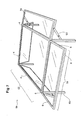
- Figure 7 is a perspective view of a construction (56), in this case a cover of pool, whose vertical walls (58) can be fold up at the right season.
- This construction (56) is erected using only elements profiles (4, 6) described above, except for the corner posts (60) which are simple hollow sections of any section, for example square.
- Construction (56) includes a fixed roof (62) whose bearing frame consists of the assembly of four elements (4).
- a cover element for example a polycarbonate panel (64) or any other material, is attached to the carrying frame.
- An advantage resulting from the use of the elements (4) to form the bearing frame is that the channel, defined between the shaft (22) of the L and the first branch (12) of the hook (10), plays the role of a gutter to collect rainwater (see Figure 1). A descent, which can possibly be fitted inside the poles angle (60) makes it possible to evacuate the water harvested in said gutter.
- the frame carrying the vertical wall (58) is to him obtained by the association of four elements (6) as described in Figure 1; this frame supports a panel (64), for example polycarbonate, fixed by means of appropriate fixation.
- the assembly of elements to form the bearing frame can be made by a miter cut, to using brackets, riveting or welding.
- the frame carrying the vertical wall (58), once assembled, is put in cooperation with the the fixed roof by interlocking or embedding the hook (26) inside the hook (10).
- a jack system (65) actuated in a manner pneumatic, hydraulic or electrical can be used to connect the corner posts (60) with each element (6) constituting the vertical side of the frame of the vertical wall (58).
- Figure 8 is a representation in section of one of the corners of the construction when the vertical walls were folded towards the low.
- the first branch (28) of the hook (26) of the second element (6) provides a better resistance to gusts of wind by accentuating the rigidity of the corner post (60) in the diagonal direction.
- a material sealing ring (66) is applied to the outer surface of the shaft (32) of the L and on the first branch (28) of the hook (26). This sealing material (66) on the one hand, to improve the hermetic integrity of the building when the vertical wall (58) is closed and, on the other hand, to cushion the shocks between the elements (6) and the corner posts (60) when closing, while reducing the coefficient of friction between elements (6) and the corner posts (60).
- Fig. 9 is another embodiment of body (24) of the second element (4) in which the shaft (22) of the L has a curvature in the shape of a corner post (60) of circular section.
Landscapes
- Engineering & Computer Science (AREA)
- Architecture (AREA)
- Physics & Mathematics (AREA)
- Electromagnetism (AREA)
- Civil Engineering (AREA)
- Structural Engineering (AREA)
- Mechanical Engineering (AREA)
- Tents Or Canopies (AREA)
Priority Applications (1)
| Application Number | Priority Date | Filing Date | Title |
|---|---|---|---|
| EP04101563A EP1586729A1 (de) | 2004-04-15 | 2004-04-15 | Scharniersystem |
Applications Claiming Priority (1)
| Application Number | Priority Date | Filing Date | Title |
|---|---|---|---|
| EP04101563A EP1586729A1 (de) | 2004-04-15 | 2004-04-15 | Scharniersystem |
Publications (1)
| Publication Number | Publication Date |
|---|---|
| EP1586729A1 true EP1586729A1 (de) | 2005-10-19 |
Family
ID=34928962
Family Applications (1)
| Application Number | Title | Priority Date | Filing Date |
|---|---|---|---|
| EP04101563A Withdrawn EP1586729A1 (de) | 2004-04-15 | 2004-04-15 | Scharniersystem |
Country Status (1)
| Country | Link |
|---|---|
| EP (1) | EP1586729A1 (de) |
Cited By (1)
| Publication number | Priority date | Publication date | Assignee | Title |
|---|---|---|---|---|
| CN110725626A (zh) * | 2019-10-28 | 2020-01-24 | 成都德泽停车场管理有限公司 | 一种高强度g型扣合件及扣合结构 |
Citations (4)
| Publication number | Priority date | Publication date | Assignee | Title |
|---|---|---|---|---|
| US974953A (en) * | 1910-03-19 | 1910-11-08 | George W Darlinton | Storm window or screen hanger. |
| US1666211A (en) * | 1926-03-22 | 1928-04-17 | Motor Products Corp | Windshield hinge |
| US4308972A (en) * | 1980-08-29 | 1982-01-05 | Power-Flame, Inc. | Separable hinge assembly for a door |
| US4852213A (en) * | 1987-10-13 | 1989-08-01 | Peter Shewchuk | Releasable extruded hinge |
-
2004
- 2004-04-15 EP EP04101563A patent/EP1586729A1/de not_active Withdrawn
Patent Citations (4)
| Publication number | Priority date | Publication date | Assignee | Title |
|---|---|---|---|---|
| US974953A (en) * | 1910-03-19 | 1910-11-08 | George W Darlinton | Storm window or screen hanger. |
| US1666211A (en) * | 1926-03-22 | 1928-04-17 | Motor Products Corp | Windshield hinge |
| US4308972A (en) * | 1980-08-29 | 1982-01-05 | Power-Flame, Inc. | Separable hinge assembly for a door |
| US4852213A (en) * | 1987-10-13 | 1989-08-01 | Peter Shewchuk | Releasable extruded hinge |
Cited By (1)
| Publication number | Priority date | Publication date | Assignee | Title |
|---|---|---|---|---|
| CN110725626A (zh) * | 2019-10-28 | 2020-01-24 | 成都德泽停车场管理有限公司 | 一种高强度g型扣合件及扣合结构 |
Similar Documents
| Publication | Publication Date | Title |
|---|---|---|
| EP1395724B1 (de) | Schwimmbeckenüberdachung aus gelenkig verbundenen dachelementen | |
| EP0224290B1 (de) | Bauart einer abdeckbaren Bedachung | |
| EP0911469B1 (de) | Drehbare Tür mit einem Flügel, an dem zwei parallele Treibstangen mittels zweiarmiger Hebel montiert sind | |
| EP3767049B1 (de) | Pergola beinhaltend eine tragende struktur und ein faltbares beschattungselement | |
| EP1586729A1 (de) | Scharniersystem | |
| FR2577122A1 (fr) | Parapluie raccourcissable | |
| WO2000037274A1 (fr) | Dispositif de securite pour baie vitree a volet mobile | |
| EP2118418B1 (de) | Scharniersystem für ein sektionaltor, sektionaltor und befestigungsverfahren dafür | |
| EP4010550A1 (de) | Entfaltbares zelt mit biegebeanspruchten bögen | |
| FR2643110A1 (fr) | Store, notamment pour verandas, comprenant une barre de charge associee a des guides | |
| EP3431692B1 (de) | Einheit für ein fenster, eine fenstertür oder einen fensterladen | |
| FR2768767A1 (fr) | Persienne coulissante a charniere | |
| FR2852990A1 (fr) | Piece d'assemblage de profiles de structure, notamment pour la realisation d'un abri de piscine et abri de piscine utilisant de telles pieces | |
| EP3656952B1 (de) | Schutzstruktur vom typ carport | |
| FR2722828A1 (fr) | Porte accordeon | |
| EP1247914B1 (de) | Elementanordnung zur Herstellung einer Schiebetür für einen Schutzraum | |
| FR2678308A1 (fr) | Lanterneau d'aeration formant exutoire de fumees en toiture a forte capacite de charge et grande ouverture. | |
| FR2666365A1 (fr) | Escalier articule escamotable. | |
| FR2973346A1 (fr) | Structure pliable/deployable a deploiement spontane et verrouillage spontane a l'etat deploye | |
| FR2825737A1 (fr) | Toiture de piscine pour abris bas a elements de toiture articules | |
| EP1396603B1 (de) | Sektionaltorblatt und damit versehenes Tor | |
| FR3074509A1 (fr) | Element de couverture, abri et procede associe | |
| EP1605130A1 (de) | Fingerschutz | |
| EP0624698A1 (de) | Entlüftungsvorrichtung für ein Tonnengewölbe | |
| FR2729690A1 (fr) | Exutoire de fumees a fermeture par cable |
Legal Events
| Date | Code | Title | Description |
|---|---|---|---|
| PUAI | Public reference made under article 153(3) epc to a published international application that has entered the european phase |
Free format text: ORIGINAL CODE: 0009012 |
|
| AK | Designated contracting states |
Kind code of ref document: A1 Designated state(s): AT BE BG CH CY CZ DE DK EE ES FI FR GB GR HU IE IT LI LU MC NL PL PT RO SE SI SK TR |
|
| AX | Request for extension of the european patent |
Extension state: AL HR LT LV MK |
|
| 17P | Request for examination filed |
Effective date: 20060413 |
|
| AKX | Designation fees paid |
Designated state(s): AT BE BG CH CY CZ DE DK EE ES FI FR GB GR HU IE IT LI LU MC NL PL PT RO SE SI SK TR |
|
| AXX | Extension fees paid |
Extension state: MK Payment date: 20060419 Extension state: LV Payment date: 20060419 Extension state: LT Payment date: 20060419 Extension state: HR Payment date: 20060419 Extension state: AL Payment date: 20060419 |
|
| STAA | Information on the status of an ep patent application or granted ep patent |
Free format text: STATUS: THE APPLICATION IS DEEMED TO BE WITHDRAWN |
|
| 18D | Application deemed to be withdrawn |
Effective date: 20061028 |