EP1591073A1 - Sonde ultrasonore et dispositif ultrasonore - Google Patents
Sonde ultrasonore et dispositif ultrasonore Download PDFInfo
- Publication number
- EP1591073A1 EP1591073A1 EP04706363A EP04706363A EP1591073A1 EP 1591073 A1 EP1591073 A1 EP 1591073A1 EP 04706363 A EP04706363 A EP 04706363A EP 04706363 A EP04706363 A EP 04706363A EP 1591073 A1 EP1591073 A1 EP 1591073A1
- Authority
- EP
- European Patent Office
- Prior art keywords
- therapeutic
- ultrasound
- transducers
- diagnostic
- ultrasounds
- Prior art date
- Legal status (The legal status is an assumption and is not a legal conclusion. Google has not performed a legal analysis and makes no representation as to the accuracy of the status listed.)
- Withdrawn
Links
Images



Classifications
-
- A—HUMAN NECESSITIES
- A61—MEDICAL OR VETERINARY SCIENCE; HYGIENE
- A61B—DIAGNOSIS; SURGERY; IDENTIFICATION
- A61B8/00—Diagnosis using ultrasonic, sonic or infrasonic waves
- A61B8/54—Control of the diagnostic device
- A61B8/546—Control of the diagnostic device involving monitoring or regulation of device temperature
-
- A—HUMAN NECESSITIES
- A61—MEDICAL OR VETERINARY SCIENCE; HYGIENE
- A61B—DIAGNOSIS; SURGERY; IDENTIFICATION
- A61B8/00—Diagnosis using ultrasonic, sonic or infrasonic waves
- A61B8/08—Clinical applications
- A61B8/0808—Clinical applications for diagnosis of the brain
- A61B8/0816—Clinical applications for diagnosis of the brain using echo-encephalography
-
- A—HUMAN NECESSITIES
- A61—MEDICAL OR VETERINARY SCIENCE; HYGIENE
- A61B—DIAGNOSIS; SURGERY; IDENTIFICATION
- A61B8/00—Diagnosis using ultrasonic, sonic or infrasonic waves
- A61B8/48—Diagnostic techniques
- A61B8/481—Diagnostic techniques involving the use of contrast agents, e.g. microbubbles introduced into the bloodstream
-
- A—HUMAN NECESSITIES
- A61—MEDICAL OR VETERINARY SCIENCE; HYGIENE
- A61N—ELECTROTHERAPY; MAGNETOTHERAPY; RADIATION THERAPY; ULTRASOUND THERAPY
- A61N7/00—Ultrasound therapy
-
- A—HUMAN NECESSITIES
- A61—MEDICAL OR VETERINARY SCIENCE; HYGIENE
- A61B—DIAGNOSIS; SURGERY; IDENTIFICATION
- A61B17/00—Surgical instruments, devices or methods
- A61B17/22—Implements for squeezing-off ulcers or the like on inner organs of the body; Implements for scraping-out cavities of body organs, e.g. bones; for invasive removal or destruction of calculus using mechanical vibrations; for removing obstructions in blood vessels, not otherwise provided for
- A61B17/22004—Implements for squeezing-off ulcers or the like on inner organs of the body; Implements for scraping-out cavities of body organs, e.g. bones; for invasive removal or destruction of calculus using mechanical vibrations; for removing obstructions in blood vessels, not otherwise provided for using mechanical vibrations, e.g. ultrasonic shock waves
-
- A—HUMAN NECESSITIES
- A61—MEDICAL OR VETERINARY SCIENCE; HYGIENE
- A61B—DIAGNOSIS; SURGERY; IDENTIFICATION
- A61B90/00—Instruments, implements or accessories specially adapted for surgery or diagnosis and not covered by any of the groups A61B1/00 - A61B50/00, e.g. for luxation treatment or for protecting wound edges
- A61B90/36—Image-producing devices or illumination devices not otherwise provided for
- A61B90/37—Surgical systems with images on a monitor during operation
- A61B2090/378—Surgical systems with images on a monitor during operation using ultrasound
Definitions
- the present invention relates to an ultrasound probe and an ultrasound apparatus for use in ultrasound therapy.
- therapeutic ultrasounds are emitted via a diagnostic probe kept in contact with the body surface of a subject, and ultrasound images (e.g. tomograms and M-mode images) are reconstructed on the basis of reflected echo signals generated from the subject. Also, a target region is uninvasively treated by emitting therapeutic ultrasounds onto the subject via a therapeutic probe.
- ultrasound images e.g. tomograms and M-mode images
- a diagnostic probe and a therapeutic probe are usually arranged alongside each other on the body surface of the subject in order to emit therapeutic ultrasounds while checking the target region by its ultrasound images (see, e.g., Japanese Patent Application Laid-Open No. 5-220152).
- An object of the present invention is to realize an ultrasound probe and an ultrasound apparatus suitable for use in ultrasound therapy.
- an ultrasound probe pertaining to the invention comprises therapeutic transducers, including a plurality of arrayed first transducer elements, for emitting therapeutic ultrasounds to a subject; and diagnostic transducers, including a plurality of arrayed second transducer elements, for emitting diagnostic ultrasounds to the subject and receiving the diagnostic ultrasounds reflected by the subject, wherein the therapeutic transducers and the diagnostic transducers are stacked.
- the control accuracy of the position of irradiation with the therapeutic ultrasounds can be enhanced.
- the center of the aperture of the therapeutic transducers can be so positioned as to coincide with that of the aperture of the diagnostic transducers.
- an ultrasound apparatus pertaining to the invention comprises the aforementioned ultrasound probe; a therapeutic transmitting device for generating driving signals for the therapeutic transducers; a diagnostic transmitting device for generating driving signals for the diagnostic transducers; an image constructing device for reconstructing ultrasound images on the basis of reflected echo signals received by the diagnostic transducers; and a detecting means for detecting the state of the therapy of the subject with the therapeutic ultrasounds, wherein the therapeutic transmitting device has a warning function to output warning information on the basis of the state of the therapy detected by the detecting means.
- the operator since it is possible to detect the progress of therapy with therapeutic ultrasounds, the operator is enabled to stop the ultrasound therapy by an alarm sounded or a warning message displayed, resulting in increased operating ease of the ultrasound apparatus. Also, the target region can be prevented from being excessively irradiated with therapeutic ultrasounds.
- This embodiment is one example of an ultrasound probe in which a plurality of diagnostic transducers are stacked over the ultrasound emitting faces of therapeutic transducers.
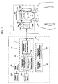
- an ultrasound apparatus 1 is configured of a diagnostic ultrasound unit 9, a therapeutic ultrasound transmitting unit 24, a display device 18, an input device 20, a control device 21 and so forth.
- the diagnostic ultrasound unit 9 is provided with a diagnostic transmitting/receiving device 12 having a diagnostic transmitting device, an image composing device including a tomogram forming device 14 and a blood stream image forming device 16, and so forth.
- the therapeutic ultrasound transmitting unit 24 is provided with a therapeutic transmitting device 25, an alarming device 27 and so forth. And the diagnostic transmitting/receiving device 12 and the therapeutic transmitting device 25 are connected to an ultrasound probe 10.
- the diagnostic transmitting/receiving device 12 generates driving signals for transmitting diagnostic ultrasounds to the ultrasound probe 10, and receives reflected echo signals outputted from the ultrasound probe 10.
- the tomogram forming device 14 reconstructs tomograms on the basis of the reflected echo signals.
- the blood stream image forming device 16 figures out the blood stream velocity from the Doppler shift of reflected echo signals and reconstructs blood stream images on that basis.
- the therapeutic transmitting device 25 generates driving signals for emitting therapeutic ultrasounds to the ultrasound probe 10.
- the alarming device 27 has a warning function of sounding a buzz or displaying a warning message at an input instruction.
- the display device 18 displays tomograms and blood stream images on the display screen of a monitor.
- the input device 20 is formed to have a keyboard and a pointing device, such as a mouse.
- the ultrasound probe 10 emits ultrasounds for diagnostic and therapeutic purposes, and is contained in a headset 11.
- the headset 11 comprises the ultrasound probe 10 and a probe cooling device including water bags 32a and 32b, a circulation path 36 and a radiator device 34.
- the water bags 32a and 32b are formed in a bag shape, holding a coolant (e.g. water) within. Incidentally, the water bags 32a and 32b need not be bag-shaped.
- the circulation path 36 guides water in the water bags 32a and 32b to the radiator device 34.
- the radiator device 34 radiates the heat of the guided water into the external atmosphere.
- the headset 11 is put on the head of the subject. This causes the water bags 32a and 32b of the headset 11 to be fixed in a state of being in contact with the outer skin (e.g. near the temples) of the subject's head. And the ultrasound probe 10 is brought into contact with the rear face of the water bag 32a.
- driving signals are supplied to the ultrasound probe 10 from the diagnostic transmitting/receiving device 12.
- the supplied driving signals cause diagnostic ultrasounds to be emitted towards the subject from the ultrasound probe 10.
- the emitted diagnostic ultrasounds are reflected or scattered by living tissues or the blood stream within the head.
- Those diagnostic ultrasounds are received by the ultrasound probe 10 as reflected echo signals.
- the received reflected echo signals are reconstructed into tomograms by the tomogram forming device 14.
- the reconstructed tomograms are displayed on the monitor of the display device 18. By observing the displayed tomograms, the position of the target region (e.g. cerebral thrombosis) can be accurately identified.
- the target region e.g. cerebral thrombosis
- the input of the position of the target region (e.g. cerebral thrombosis) in the tomograms is set from the input device 20.
- driving signals are generated by the therapeutic transmitting device 25.
- the generated driving signals are supplied to the therapeutic transmitting device 25 of the ultrasound probe 10. This enables the cerebral thrombosis to be irradiated with therapeutic ultrasounds from the ultrasound probe 10 to dissolve the cerebral thrombosis uninvasively.
- the blood vessel When the cerebral thrombosis is dissolved, the blood vessel is reopened to let the blood flow.
- the blood which has begun to flow causes diagnostic ultrasounds to be reflected or scattered as reflected echo signals.
- the Doppler shift of those reflected echo signals is figured out by the blood stream image forming device.
- blood stream images e.g. two-dimensional Doppler blood stream images or pulse Doppler FFT measured images
- the target region can be precisely irradiated with therapeutic ultrasounds by using an ultrasound probe integrally formed by stacking diagnostic transducers and therapeutic transducers.
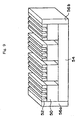
- the ultrasound probe 10 is composed by stacking diagnostic transducers 52, therapeutic transducers 50, a backing material 54 and a cooling device 56 in this order from the subject side.
- the therapeutic transducers 50 generate ultrasounds of a relatively low frequency (e.g. about 500 kHz) while the diagnostic transducers 52 generate ultrasounds of a relatively high frequency (e.g. about 2 MHz). Therefore, as the ultrasounds generated by the diagnostic transducers 52 are more difficult to be transmitted by an obstacle than the ultrasounds generated by the therapeutic transducers 50 are, the diagnostic transducers 52 are stacked over the therapeutic transducers 50 so that the former can be closer to the subject.
- the therapeutic transducers 50 are formed by arraying a plurality of transducer elements 50a through 50d.
- the therapeutic transducer elements 50a through 50d are arrayed at equal intervals with the longitudinal directions of ultrasound emitting faces 51 being parallel to one another.
- the arrayed therapeutic transducer elements 50a through 50d convert the driving signals from the therapeutic ultrasound transmitting unit 24 into mechanical transducers, and deflect them to emit therapeutic ultrasounds to the target region (e.g. cerebral thrombosis).
- the diagnostic transducers 52 are formed by arraying a plurality of transducer elements 52a through 52p.
- the diagnostic transducer elements 52a through 52p are made smaller than the transducer elements 50a through 50d of the therapeutic transducers 50 in order to enhance the resolution of the tomograms to be reconstructed.
- more than one of diagnostic transducer elements 52a through 52p are distributed over the ultrasound emitting faces 51. For example, as shown in Figure 2, the diagnostic transducer elements 52a through 52d are distributed over the ultrasound emitting face 51 of the therapeutic transducer element 50a.
- the reverse faces of the diagnostic transducer elements 52a through 52d to an ultrasound emitting face 53 are joined to the ultrasound emitting faces 51 of the therapeutic transducer element 50a.
- the diagnostic transducer elements 52a through 52d are arranged at equal intervals in the shorter side direction of the ultrasound emitting face 51 and in parallel to the longitudinal direction of the ultrasound emitting face 53.
- the diagnostic transducer elements 52e through 52p converts electric signals, e.g. in a pulse form, from the transmitting/receiving device 12 into mechanical transducers, deflects them to transmit diagnostic ultrasounds to the subject, and at the same time receives reflected echo signals generated from the subject and converts them into electric signal pulses.
- the backing material 54 is formed of, among other things, a low-impedance layer having a thickness of half the wavelength of the therapeutic ultrasounds, and disposed superposing over the reverse faces of the therapeutic transducer elements 50a through 50d to the ultrasound emitting faces 51. This causes ultrasounds to be transmitted to the side reverse to the emitting direction, out of the ultrasounds emitted from the therapeutic transducers 50, to be reflected by the backing material 54 and proceed towards the subject. Therefore, it is possible to efficiently emit therapeutic ultrasounds towards the subject.
- the cooling device 56 is disposed superposing over the reverse face of the backing material 54, i.e. the face reverse to the ultrasound emitting direction of the therapeutic transducers 50.
- the cooling device 56 formed of a Peltier element or the like, absorbs heat by the Peltier effect when a current is let flow through it, and radiates the heat into the external atmosphere. It can thereby restrain the temperature rise of the ultrasound probe 10.
- f 1 is the frequency of the therapeutic ultrasounds emitted from the therapeutic transducers 50; ⁇ 1 , the wavelength of the therapeutic ultrasounds; f 2 , the frequency of the diagnostic ultrasounds emitted from the diagnostic transducers 52; ⁇ 2 , the wavelength of the diagnostic ultrasounds; c, the longitudinal wave sound velocity of the therapeutic transducers 50 in the thickness direction
- the dimensions are such as stated above, even if, for example, the opening where the skull is thin and permits relatively ready transmission of ultrasounds (e.g. near the temples) is limited to 30 mm square for example, the ultrasound aperture D of the ultrasound probe 10 can be accommodated within that range. Therefore, the losses of the diagnostic ultrasounds and of the therapeutic ultrasounds due to the thickness of the skull can be reduced.
- the distances d 1 between the therapeutic transducer elements and the distances d 2 between the diagnostic transducer elements should be as narrow as practicable.
- the frequencies of the ultrasounds to be used are determined from the viewpoints of effectiveness and safety. For example, where the limit value of the ultrasound intensity of the therapeutic ultrasounds is 720 mW/cm, in order to keep the temperature of the living tissue at 2°C or less, the frequency f 1 is kept at 580 kHz or less. This makes it possible to keep the thermal index (TI), the indicator of the intensity of the thermal action of ultrasounds, at no more than 2. Further, the frequency f 1 is adjusted to 390 kHz or above. This makes it possible to keep the mechanical index (MI), the indicator of the intensity of the mechanical action of ultrasounds to destroy tissue cells by cavitations or the like arising within the blood vessel, at 0.25 or below.
- TI thermal index
- MI mechanical index
- an ultrasound probe 10 having four therapeutic transducer elements 50a through 50d and sixteen diagnostic transducer elements 52a through 52p was described, but the number of transducer elements of each type can be altered as appropriate.
- the ratio between the array pitch of therapeutic transducer elements and the array pitch of diagnostic transducer elements is integral, the phase control system and the circuit form can be simplified.
- sound insulators 53 are provided to fill the gaps between the therapeutic transducer elements and constitute the base of the diagnostic transducer elements.
- Examples of material for the sound insulators 53 include particulates of tungsten or the like and micro-balloons dispersed in epoxy resin. If the configuration is such that the ratio between the array pitch of therapeutic transducer elements and the array pitch of diagnostic transducer elements is not integral as shown in Figure 4, an arrangement in which the gratings of the two types of transducer elements do not degenerate can be realized, and control can be so performed as not to let the grating lobes overlap each other.
- a therapeutic ultrasound beam (T beam) and a diagnostic ultrasounds beam (D beam) are alternately emitted, each at a set point of time.
- the emission timings of the T beam and the D beam may be altered as appropriate to prevent noise generation.
- the D beam (e.g. 2 MHz in frequency) is emitted from the diagnostic transducers 52 for 0.2 second for example.
- the T beam (e.g. 500 kHz in frequency) is emitted from therapeutic transducers 50 for 3 seconds for example. Repetition of such actions causes the D beam to form a tomogram and a two-dimensional blood stream image and the T beam to treat the target region.
- the duration is set, for example, in a range of 0.01 to 0.2 second.
- the duration of T beam emission is set, for example, between 1 and 10 seconds as appropriate.
- the D beam is formed by transmitting at set intervals a burst wave consisting of pulse waveforms put together over 1/2 to 20 wavelengths, for example.
- the T beam is formed by transmitting consecutively transmitted ultrasounds so that a prescribed mechanical index can be secured.
- the scanning coordinates of the T beam from the therapeutic transducers 50 and those of the D beam from the diagnostic transducers 52 can be so positioned as to coincide with each other, the position of irradiation with therapeutic ultrasounds can be more accurately controlled. Therefore, the target region whose position has been identified with the D beam can be accurately irradiated with the T beam.
- tomograms are reconstructed by using the D beam and the target region can be treated by using the T beam. Therefore, the length of time required for treatment can be shortened, and the efficiency of ultrasound therapy can be enhanced in other ways as well. For example, whereas any cerebral thrombosis should be dissolved in a short period from the time when a cerebral infarction has occurred, the cerebral thrombosis can be dissolved promptly and accurately in this embodiment.
- FIG. 6 shows a configurative diagram of an ultrasound apparatus of this embodiment.
- a blood stream detecting device 22 is provided in this embodiment as shown in Figure 6.
- the therapeutic transmitting device 25 maintains or increases the energy (e.g. amplitude or frequency) of therapeutic ultrasounds. Or if it is determined that the detected blood stream velocity is above the setpoint, a control instruction will be outputted to the therapeutic ultrasound transmitting unit 24, and the therapeutic transmitting device 25 will either reduce the energy or totally stop the emission of therapeutic ultrasounds. Then, the alarming device 27 issues a warning sound (e.g. buzz or voice) or displays a warning message on the display device 18.
- a warning sound e.g. buzz or voice
- FIG. 7 shows a configurative diagram of an ultrasound apparatus in this embodiment.
- a temperature detecting device 28 is provided in this embodiment as shown in Figure 7.
- the therapeutic transmitting device 25 maintains or increases the energy (e.g. amplitude or frequency) of therapeutic ultrasounds. Or if it is determined that the detected temperature rise exceeds the setpoint, a control instruction will be outputted to the therapeutic ultrasound transmitting unit 24, and the therapeutic transmitting device 25 will either reduce the energy or totally stop the emission of therapeutic ultrasounds. Then, the alarming device 27 issues a warning sound (e.g. buzz or voice) or displays a warning message on the display device 18.
- a warning sound e.g. buzz or voice
- the temperature rise can be prevented from inviting any side effect on the living tissue.
- the temperature of the water bag 32a shown in Figure 1 can be detected. In short, the point is to detect a temperature correlated to the therapeutic transducers 50 or the diagnostic transducers 52.
- FIG. 8 shows a configurative diagram of an ultrasound apparatus in this embodiment.
- the thrombosis is irradiated with therapeutic ultrasounds, while a thrombolytic agent is injected into the subject to accelerate the dissolution of the thrombosis.
- the thrombolytic agent may continue to be injected into the subject even after the thrombosis has been dissolved and blood begins to flow.
- a solvent injection control unit 30 is provided in this embodiment as shown in Figure 8.
- the solvent injection control unit 30 has an injection control device 31, an arithmetic processing device 29, an alarming device 33 and so forth.
- the injection control device 31 controls the dose of the thrombolytic agent injected into the subject via an injector probe 26.
- the arithmetic processing device 29 computes the dose of the thrombolytic agent to be injected into the subject on the basis of a control instruction from the blood stream detecting device 22.
- the alarming device 33 sounds a warning buzzer or displays a warning message on the basis of a control instruction from the blood stream detecting device 22.
- the injection control device 31 maintains or increases the dose of the thrombolytic agent. Or if it is determined that the detected blood stream velocity exceeds the setpoint ( ⁇ ), a control instruction will be issued to the solvent injection control unit 30, and the injection control device 31 will decrease the injected dose or stop the injection of the thrombolytic agent on the basis of the dose computed by the arithmetic processing device 29. Further, the alarming device 33 issues a buzz or voice or displays a warning message on the monitor 18.
- This embodiment enables the injected dose of the thrombolytic agent to be reduced or their emission to be stopped automatically when the thrombosis has been dissolved and blood begins to flow. Therefore, the living tissue can be prevented from suffering a side effect due to an excessive dose of the thrombolytic agent.
- the injected dose of the thrombolytic agent may be displayed on the display screen of the monitor 18 on a real time basis. This would enable the operator to objectively keep track of the injected dose of the thrombolytic agent.
- the ultrasound apparatus of this embodiment can also be applied where the diagnostic probe and the therapeutic probe are separated from each other.
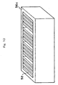
- FIG. 9 shows the ultrasound probe in this embodiment.
- cooling devices 56a and 56b are disposed on two sides of the therapeutic transducers 50 and the diagnostic transducers 52.
- the heat of the ultrasound probe 10 can be radiated into the external atmosphere by appropriately letting a current flow through the cooling devices 56a and 56b. Therefore, it is made possible to continuously irradiate the target region with ultrasounds for a relatively long time while keeping the temperature rise of the ultrasound probe 10 at or below a setpoint (e.g. 2°C).
- a setpoint e.g. 2°C
- cooling devices 56 can be installed in any positions if only they can cool the therapeutic transducers 50 or the diagnostic transducers 52.
- a cooling device 56c can be so disposed as to cover sidewalls surrounding the ultrasound probe 10.
- a metallic foil 60 is arranged over the ultrasound emitting faces of the diagnostic transducers 52 of Figure 9.
- the metallic foil 60 so arranged is in contact with the cooling devices 56a and 56b. This enables the heat generated by the diagnostic transducers 52 to be absorbed by the metallic foil 60.
- the absorbed heat is guided to the cooling devices 56a and 56b via the metallic foil 60.
- the guided heat is radiated by the Peltier effect of the cooling devices 56a and 56b. Therefore, the temperature rise of the ultrasound probe 10 can be restrained.
- the metallic foil 60 is a conductor (e.g. metal) thinned to a few ⁇ m, formed of a material which would not affect emission of ultrasounds.
- the ultrasound emitting faces of the diagnostic transducers 52 are covered by the metallic foil 60, when the ultrasound probe 10 is brought into contact with the body surface, the temperature of the ultrasound probe 10 is not directly transmitted to the subject. Therefore, the temperature of the ultrasound probe 10 can be prevented from causing a side effect to the subject.
- a sixth embodiment to which an ultrasound probe and an ultrasound apparatus according to the invention are applied will be described.
- This embodiment differs from the first through fifth embodiments in that therapeutic ultrasounds in a burst wave form are emitted to avoid occurrence of any side effect on the living tissue.
- therapeutic ultrasounds brought incident into the brain from the ultrasound probe 10 may be reflected back by the inner wall of the skull in their proceeding direction. This would occur because the skull is higher in acoustic impedance than the living tissues within the brain.
- the superposing of reflected therapeutic ultrasounds (hereinafter referred to as reflected waves) over the therapeutic ultrasounds (hereinafter referred to as incident waves) brought incident into the brain from the ultrasound probe 10 and their mutual interference may give rise to standing waves within the brain. If the standing waves have a relatively high strength (amplitude) locally, they may bring on a side effect on the living tissues within the brain.
- the therapeutic transmitting device 25 generates driving signals of a burst wave from the basic waveform in this embodiment.
- the burst wave is emitted from the therapeutic transducers 50 to the subject.
- the duration of the burst wave then is set to be relatively short (i.e. 10 ⁇ s), and the rest duration, relatively long (e.g. 100 ⁇ s to 300 ⁇ s).
- the rest duration of the burst wave is set longer than 100 ⁇ s.
- the emitting duration and the rest duration of the burst wave which are altered as appropriate, are set in advance from the input device 20.
- the burst waves T n and T n+1 do not overlap each other, so that any side effect on the living tissue can be avoided.
- Therapeutic ultrasounds are less susceptible to attenuation when proceeding within the brain, because their frequency is, for example, 500 kHz. Since the intensity of the reflected wave and that of the incident wave are approximately equal for this reason, the intensity of the interfering wave is relatively high. In this respect, this embodiment enables interference between the reflected wave and the incident wave of therapeutic ultrasounds to be averted.
- Diagnostic ultrasounds since their frequency is usually set to, for example, 2 MHz or above, are more susceptible to attenuation when proceeding within the brain. Therefore, the intensity of the interfering wave is relatively low and, as in the case of diagnostic ultrasounds, the rest duration of the pulse wave or the burst wave may be set relatively long.
- the duration of burst wave emission is supposed to be 10 ⁇ s for example, it may be altered as appropriate. The point is that, the duration may be of any length only if, even when the incident wave and the reflected wave interfere with each other, it is made possible to keep the duration of the interfering wave short to avoid its side effect on the living tissue.
- the ultrasound apparatus of this embodiment can also be applied where the diagnostic probe and the therapeutic probe are separated from each other.
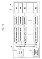
- FIG. 12 shows a configurative diagram of the therapeutic transmitting device 25 of Figure 1.
- the therapeutic ultrasound transmitting device 24 comprises a clock generator 70, a modulating signal generator 72, phase shifter circuits 74a through 74m (m: a natural number), amplifiers (hereinafter referred to as amplifiers 76a through 76m).
- the phase shifter circuits 74a through 74m can be formed of delay circuits. Sign m matches the number of therapeutic transducer elements 50a through 50m constituting the ultrasound probe 10.
- the basic waveform of a continuous wave is generated by the clock generator 70.
- the generated basic waveform is shifted in phase by the phase shifter circuits 74a through 74m.
- each shifted basic waveform after being amplified by the amplifiers 76a through 76m, is inputted to the therapeutic transducers 50 as a driving signal.
- the inputted driving signals cause the therapeutic transducers 50 to emit therapeutic ultrasounds.
- the modulating signal generator 72 With the lapse of the emission time, the modulating signal generator 72 generates modulating signals.
- the generated modulating signals are inputted to the phase shifter circuits 74a through 74m. With the inputted modulating signals, the phase shifter circuits 74a through 74m significantly modulate the frequencies of the basic waveforms.
- the modulated waveforms are inputted to the therapeutic transducers 50 as driving signals.
- This causes therapeutic ultrasounds whose frequencies are significantly modulated to be emitted from the therapeutic transducers 50.
- the overlapping reflected wave and incident wave will differ in frequency. Since the interference pattern between the reflected wave and the incident wave therefore is not fixed, the intensity of the interference wave generated by the interference between the reflected wave and the incident wave can be restrained.
- the frequency of therapeutic ultrasounds is modulated every time an emitted ultrasound is transmitted from the brain surface into the skull and proceeds into the brain (e.g. 10 ⁇ S) so that the inference pattern of the therapeutic ultrasounds may not be fixed at all.
- the frequency should be modulated in the direction of the time axis on the basis of the basic waveforms.
- the modulation value of the frequency can be set as appropriate. For example, if the frequency is so modulated that the reflected wave and the incident wave deviated from each other by 1/4 to 1/2 wavelength, the reflected wave and the incident wave will so interfere as to cancel each other. Therefore, the intensity of the interference wave can be further prevented from increasing.
- the ultrasound apparatus of this embodiment can also be applied where the diagnostic probe and the therapeutic probe are separated from each other.
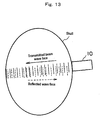
- FIG. 12 is a diagram for describing the principle of avoiding interference between the incident wave and the reflected wave.
- preset delay data are assigned to the phase shifter circuits 74a through 74m at every set time (e.g. 0.1 second). As this causes the ultrasounds emitted from the therapeutic transducers 50 to be deflected, the emitting direction of the ultrasound beam is altered.
- the angle ( ⁇ ) of altering the ultrasound beam may be changed as appropriate.
- the proceeding direction of the incident wave and that of the reflected wave of the therapeutic ultrasounds are no longer on the same straight line.
- the incident wave and the reflected wave become different in direction, interference between the incident wave and the reflected wave can be avoided.
- the set time for altering the emitting direction of ultrasounds is supposed to be 0.1 second in this embodiment, it can be set as appropriate.
- the interference wave may generate cavitations (bubbles) in the blood vessel.
- the generated cavitations after growing in size gradually, are ruptured.
- the impact of the cavitations may bring on a side effect on the living tissue. It is therefore desirable to alter the emitting direction of ultrasounds before cavitations arise.
- the ultrasound apparatus of this embodiment can also be applied where the diagnostic probe and the therapeutic probe are separated from each other.
- the ultrasound probe and the ultrasound apparatus according to the invention can also be applied to therapy of myocardial infarction.
- the ultrasound probe is kept in contact with the chest, and diagnostic and therapeutic ultrasounds are emitted toward the thrombosis formed in the coronary artery through gaps between chest ribs.
- the ultrasound probe and the ultrasound apparatus according to the invention can be applied not only to dissolving thromboses but also to dissolving abnormal solids formed within the body of inorganic substances or salts (e.g. calculi).
- the ultrasound probe and the ultrasound apparatus according to the invention can also be used for cerebral infarctions of various types. Cerebral infarctions, for example, include lacunar infarction, atherothrombotic infarction and cardiogenic cerebral embolism. Lacunar infarction is a small infarcted focus formed in a deep part of the brain by the twining of a thin cerebral artery due to damage by high blood pressure. Atherothrombotic infarction occurs when the sclerosis of a carotid artery or a relatively thick artery within the skull (atherosclerosis) narrows that artery, inviting the formation of a thrombosis in that position to block the blood stream.
- lacunar infarction is a small infarcted focus formed in a deep part of the brain by the twining of a thin cerebral artery due to damage by high blood pressure.
- Atherothrombotic infarction occurs when the sclerosis of a carotid artery or a relatively thick artery within the skull (a
- Cardiogenic cerebral embolism is a blockade of the blood stream by a lump of blood (thrombosis) formed in the heart, peeled off and flowing into a cerebral artery.
- thrombosis a lump of blood
- the ultrasound probe and the ultrasound apparatus according to the invention can promptly and readily dissolve the thrombosis.
- the present invention makes it possible to realize an ultrasound probe and an ultrasound apparatus well suited to ultrasound therapy.
Landscapes
- Health & Medical Sciences (AREA)
- Life Sciences & Earth Sciences (AREA)
- General Health & Medical Sciences (AREA)
- Animal Behavior & Ethology (AREA)
- Veterinary Medicine (AREA)
- Nuclear Medicine, Radiotherapy & Molecular Imaging (AREA)
- Public Health (AREA)
- Radiology & Medical Imaging (AREA)
- Engineering & Computer Science (AREA)
- Biomedical Technology (AREA)
- Medical Informatics (AREA)
- Physics & Mathematics (AREA)
- Molecular Biology (AREA)
- Surgery (AREA)
- Heart & Thoracic Surgery (AREA)
- Pathology (AREA)
- Biophysics (AREA)
- Hematology (AREA)
- Neurology (AREA)
- Ultra Sonic Daignosis Equipment (AREA)
- Surgical Instruments (AREA)
- Transducers For Ultrasonic Waves (AREA)
Applications Claiming Priority (5)
| Application Number | Priority Date | Filing Date | Title |
|---|---|---|---|
| JP2003024252 | 2003-01-31 | ||
| JP2003024252 | 2003-01-31 | ||
| JP2003352464 | 2003-10-10 | ||
| JP2003352464 | 2003-10-10 | ||
| PCT/JP2004/000812 WO2004066856A1 (fr) | 2003-01-31 | 2004-01-29 | Sonde ultrasonore et dispositif ultrasonore |
Publications (2)
| Publication Number | Publication Date |
|---|---|
| EP1591073A1 true EP1591073A1 (fr) | 2005-11-02 |
| EP1591073A4 EP1591073A4 (fr) | 2010-11-17 |
Family
ID=32828927
Family Applications (1)
| Application Number | Title | Priority Date | Filing Date |
|---|---|---|---|
| EP04706363A Withdrawn EP1591073A4 (fr) | 2003-01-31 | 2004-01-29 | Sonde ultrasonore et dispositif ultrasonore |
Country Status (4)
| Country | Link |
|---|---|
| US (1) | US7662098B2 (fr) |
| EP (1) | EP1591073A4 (fr) |
| JP (1) | JP4543430B2 (fr) |
| WO (1) | WO2004066856A1 (fr) |
Cited By (13)
| Publication number | Priority date | Publication date | Assignee | Title |
|---|---|---|---|---|
| WO2008017998A3 (fr) * | 2006-08-11 | 2008-05-08 | Koninkl Philips Electronics Nv | Système à ultrasons pour l'imagerie de la circulation sanguine cérébrale et la lyse de caillot sanguin au moyen de microbulles |
| WO2008017997A3 (fr) * | 2006-08-11 | 2008-05-08 | Koninkl Philips Electronics Nv | Système à ultrasons pour l'imagerie de la circulation sanguine cérébrale et la lyse de caillot sanguin au moyen de microbulles |
| WO2009021535A1 (fr) * | 2007-08-14 | 2009-02-19 | Campus Micro Technologies Gmbh | Dispositifs, systèmes et procédés médicaux de régulation de la pression sanguine |
| WO2010103469A1 (fr) * | 2009-03-12 | 2010-09-16 | Koninklijke Philips Electronics, N.V. | Sonolyse de caillots sanguins utilisant des impulsions d'excitation codées de faible puissance |
| WO2010058292A3 (fr) * | 2008-11-19 | 2010-10-28 | Insightec Ltd. | Lyse de caillot en boucle fermée |
| US8012092B2 (en) | 2005-08-30 | 2011-09-06 | Koninklijke Philips Electronics N.V. | Method of using a combination imaging and therapy transducer to dissolve blood clots |
| EP2101876B1 (fr) * | 2006-12-04 | 2013-01-09 | Koninklijke Philips Electronics N.V. | Dispositif de traitement de problèmes cutanés |
| US8409099B2 (en) | 2004-08-26 | 2013-04-02 | Insightec Ltd. | Focused ultrasound system for surrounding a body tissue mass and treatment method |
| US8617073B2 (en) | 2009-04-17 | 2013-12-31 | Insightec Ltd. | Focusing ultrasound into the brain through the skull by utilizing both longitudinal and shear waves |
| US8932237B2 (en) | 2010-04-28 | 2015-01-13 | Insightec, Ltd. | Efficient ultrasound focusing |
| EP2861300A4 (fr) * | 2012-06-13 | 2016-03-16 | David W Newell | Traitement de l'hématome sous-arachnoïdien par sonothrombolyse, et dispositifs, systèmes et méthodes associés |
| US9412357B2 (en) | 2009-10-14 | 2016-08-09 | Insightec Ltd. | Mapping ultrasound transducers |
| US9852727B2 (en) | 2010-04-28 | 2017-12-26 | Insightec, Ltd. | Multi-segment ultrasound transducers |
Families Citing this family (45)
| Publication number | Priority date | Publication date | Assignee | Title |
|---|---|---|---|---|
| US6618620B1 (en) | 2000-11-28 | 2003-09-09 | Txsonics Ltd. | Apparatus for controlling thermal dosing in an thermal treatment system |
| US7828754B2 (en) * | 2004-06-21 | 2010-11-09 | Hiroshi Furuhata | Ultrasonic cerebral infarction therapeutic apparatus |
| JP2006020710A (ja) * | 2004-07-06 | 2006-01-26 | Ge Medical Systems Global Technology Co Llc | 超音波撮影装置 |
| WO2006137484A1 (fr) * | 2005-06-22 | 2006-12-28 | Hitachi Medical Corporation | Appareil de traitement par ultrasons |
| US20070129652A1 (en) * | 2005-11-15 | 2007-06-07 | Henry Nita | Methods and apparatus for intracranial ultrasound therapies |
| JP4945769B2 (ja) * | 2005-07-26 | 2012-06-06 | サーフ テクノロジー アクティーゼルスカブ | 二重周波数帯域の超音波送受波器アレイ |
| US10219815B2 (en) | 2005-09-22 | 2019-03-05 | The Regents Of The University Of Michigan | Histotripsy for thrombolysis |
| US8568318B2 (en) * | 2007-02-16 | 2013-10-29 | Los Alamos National Security, Llc | High-resolution wave-theory-based ultrasound reflection imaging using the split-step fourier and globally optimized fourier finite-difference methods |
| WO2008132835A1 (fr) * | 2007-04-24 | 2008-11-06 | Panasonic Corporation | Dispositif d'échographie |
| US20080284578A1 (en) * | 2007-05-16 | 2008-11-20 | Evdokimos Mouratidis | Automobile communication device |
| US8531178B2 (en) | 2007-11-26 | 2013-09-10 | Konica Minolta Medical & Graphic, Inc. | Ultrasound probe, method for manufacturing the same, and ultrasound diagnostic apparatus |
| US20090287120A1 (en) | 2007-12-18 | 2009-11-19 | Searete Llc, A Limited Liability Corporation Of The State Of Delaware | Circulatory monitoring systems and methods |
| US9672471B2 (en) | 2007-12-18 | 2017-06-06 | Gearbox Llc | Systems, devices, and methods for detecting occlusions in a biological subject including spectral learning |
| US9717896B2 (en) | 2007-12-18 | 2017-08-01 | Gearbox, Llc | Treatment indications informed by a priori implant information |
| US20090287191A1 (en) * | 2007-12-18 | 2009-11-19 | Searete Llc, A Limited Liability Corporation Of The State Of Delaware | Circulatory monitoring systems and methods |
| US8636670B2 (en) | 2008-05-13 | 2014-01-28 | The Invention Science Fund I, Llc | Circulatory monitoring systems and methods |
| US20090292212A1 (en) * | 2008-05-20 | 2009-11-26 | Searete Llc, A Limited Corporation Of The State Of Delaware | Circulatory monitoring systems and methods |
| US8359926B2 (en) * | 2008-05-16 | 2013-01-29 | Hitachi Medical Corporation | Ultrasonic diagnostic apparatus |
| ES2736276T3 (es) | 2008-07-14 | 2019-12-27 | Arizona Board Of Regents For And On Behalf Of Arizona State Univ | Dispositivos de modulación de la actividad celular utilizando ultrasonido |
| WO2011024074A2 (fr) | 2009-08-26 | 2011-03-03 | Insightec Ltd. | Transducteur à ultrasons asymétrique en réseau phasé |
| CN105854193B (zh) * | 2009-11-04 | 2020-03-20 | 代理并代表亚利桑那州立大学的亚利桑那董事会 | 调节大脑活动的设备和方法 |
| US9694213B2 (en) * | 2009-12-31 | 2017-07-04 | St. Jude Medical, Atrial Fibrillation Division, Inc. | Acoustic coupling for assessment and ablation procedures |
| AU2012258902A1 (en) * | 2011-05-20 | 2014-01-16 | Doheny Eye Institute | Ocular ultrasound probe |
| EP2768385B1 (fr) | 2011-10-21 | 2021-03-31 | Cerevast Medical, Inc. | Système de communication directe |
| WO2014036170A1 (fr) | 2012-08-29 | 2014-03-06 | Thync, Inc. | Systèmes et dispositifs pour coupler une énergie ultrasonore au corps |
| US20140194740A1 (en) * | 2013-01-07 | 2014-07-10 | Cerebrosonics, Llc | Emboli detection in the brain using a transcranial doppler photoacoustic device capable of vasculature and perfusion measurement |
| JP2014168603A (ja) * | 2013-03-05 | 2014-09-18 | Jikei Univ | 超音波栓子検出装置 |
| US10780298B2 (en) | 2013-08-22 | 2020-09-22 | The Regents Of The University Of Michigan | Histotripsy using very short monopolar ultrasound pulses |
| JP5963811B2 (ja) * | 2014-07-18 | 2016-08-03 | オリンパス株式会社 | 治療用超音波振動子 |
| WO2016143016A1 (fr) | 2015-03-06 | 2016-09-15 | 株式会社Murakumo | Dispositif d'oscillation ultrasonore |
| EP4230262A3 (fr) | 2015-06-24 | 2023-11-22 | The Regents Of The University Of Michigan | Systèmes de thérapie par histotripsie pour le traitement de tissu cérébral |
| EP3487410B1 (fr) * | 2016-08-01 | 2025-02-12 | Cordance Medical Inc. | Ouverture guidée par ultrasons de la barrière hémato-encéphalique |
| US20210298812A1 (en) * | 2018-08-02 | 2021-09-30 | Sofwave Medical Ltd. | Devices and methods for vaginal treatments |
| CN113286552B (zh) | 2018-11-28 | 2025-05-02 | 希斯托索尼克斯公司 | 组织摧毁术系统及方法 |
| WO2021030694A1 (fr) | 2019-08-15 | 2021-02-18 | Cybersonics, Inc. | Transducteur à ultrasons et boîtier pour celui-ci |
| WO2021041797A1 (fr) * | 2019-08-30 | 2021-03-04 | Cybersonics, Inc. | Générateur d'ultrasons et dispositif de commande pour générateur d'ultrasons |
| WO2021155026A1 (fr) | 2020-01-28 | 2021-08-05 | The Regents Of The University Of Michigan | Systèmes et procédés d'immunosensibilisation par histotripsie |
| JP2023530477A (ja) | 2020-06-18 | 2023-07-18 | ヒストソニックス,インコーポレーテッド | 組織破砕音響/患者結合システムおよび方法 |
| EP4204084A4 (fr) | 2020-08-27 | 2024-10-09 | The Regents Of The University Of Michigan | Transducteur ultrasonore à capacité d'émission-réception pour l'histotripsie |
| WO2022221649A1 (fr) * | 2021-04-15 | 2022-10-20 | The Regents Of The University Of Michigan | Conception et fabrication d'un transducteur ultrasonore thérapeutique ayant des éléments modulaires amovibles de forme arbitraire et à garniture dense |
| CN113171156B (zh) * | 2021-04-23 | 2022-09-06 | 北京荷清和创医疗科技有限公司 | 植入式医疗器械的超声除栓配件 |
| IL308943A (en) | 2021-06-07 | 2024-01-01 | Univ Michigan Regents | All-inclusive ultrasound systems and methods that include histotripsy |
| EP4351718A4 (fr) | 2021-06-07 | 2025-03-26 | The Regents of The University of Michigan | Méthodes et systèmes d'histotripsie minimalement invasifs |
| AU2023366591A1 (en) | 2022-10-28 | 2025-04-24 | Histosonics, Inc. | Histotripsy systems and methods |
| WO2024221001A2 (fr) | 2023-04-20 | 2024-10-24 | Histosonics, Inc. | Systèmes d'histotripsie et procédés associés comprenant des interfaces utilisateur et des flux de travail pour la planification et la thérapie de traitement |
Family Cites Families (14)
| Publication number | Priority date | Publication date | Assignee | Title |
|---|---|---|---|---|
| JPH03151952A (ja) * | 1989-11-08 | 1991-06-28 | Matsushita Electric Ind Co Ltd | 超音波治療装置 |
| DE4227800C2 (de) * | 1991-08-21 | 1996-12-19 | Toshiba Kawasaki Kk | Thrombuslösende Behandlungsvorrichtung |
| JP3300419B2 (ja) | 1991-08-21 | 2002-07-08 | 株式会社東芝 | 血栓溶解治療装置 |
| DE69432510T2 (de) * | 1993-12-24 | 2003-12-24 | Olympus Optical Co., Ltd. | Vorrichtung zur Ultraschalldiagnose und -behandlung, wobei der Brennpunkt der therapeutischen Ultraschallwelle in einer vorbestimmten Lage innerhalb des Ultraschall-Beobachtungsbereiches verriegelt ist |
| US5560362A (en) * | 1994-06-13 | 1996-10-01 | Acuson Corporation | Active thermal control of ultrasound transducers |
| JP3754113B2 (ja) * | 1994-09-17 | 2006-03-08 | 株式会社東芝 | 超音波治療装置 |
| US5694936A (en) * | 1994-09-17 | 1997-12-09 | Kabushiki Kaisha Toshiba | Ultrasonic apparatus for thermotherapy with variable frequency for suppressing cavitation |
| US5984881A (en) * | 1995-03-31 | 1999-11-16 | Kabushiki Kaisha Toshiba | Ultrasound therapeutic apparatus using a therapeutic ultrasonic wave source and an ultrasonic probe |
| US5558092A (en) * | 1995-06-06 | 1996-09-24 | Imarx Pharmaceutical Corp. | Methods and apparatus for performing diagnostic and therapeutic ultrasound simultaneously |
| DE19635593C1 (de) * | 1996-09-02 | 1998-04-23 | Siemens Ag | Ultraschallwandler für den diagnostischen und therapeutischen Einsatz |
| US5938612A (en) * | 1997-05-05 | 1999-08-17 | Creare Inc. | Multilayer ultrasonic transducer array including very thin layer of transducer elements |
| US6425867B1 (en) * | 1998-09-18 | 2002-07-30 | University Of Washington | Noise-free real time ultrasonic imaging of a treatment site undergoing high intensity focused ultrasound therapy |
| US6635017B1 (en) * | 2000-02-09 | 2003-10-21 | Spentech, Inc. | Method and apparatus combining diagnostic ultrasound with therapeutic ultrasound to enhance thrombolysis |
| US6537224B2 (en) * | 2001-06-08 | 2003-03-25 | Vermon | Multi-purpose ultrasonic slotted array transducer |
-
2004
- 2004-01-29 EP EP04706363A patent/EP1591073A4/fr not_active Withdrawn
- 2004-01-29 US US10/543,916 patent/US7662098B2/en not_active Expired - Fee Related
- 2004-01-29 JP JP2005504740A patent/JP4543430B2/ja not_active Expired - Fee Related
- 2004-01-29 WO PCT/JP2004/000812 patent/WO2004066856A1/fr not_active Ceased
Cited By (18)
| Publication number | Priority date | Publication date | Assignee | Title |
|---|---|---|---|---|
| US8409099B2 (en) | 2004-08-26 | 2013-04-02 | Insightec Ltd. | Focused ultrasound system for surrounding a body tissue mass and treatment method |
| US8012092B2 (en) | 2005-08-30 | 2011-09-06 | Koninklijke Philips Electronics N.V. | Method of using a combination imaging and therapy transducer to dissolve blood clots |
| JP2014000431A (ja) * | 2006-08-11 | 2014-01-09 | Koninklijke Philips Nv | 脳血流画像化、及びマイクロバブルを用いた血餅溶解をする超音波システム |
| WO2008017997A3 (fr) * | 2006-08-11 | 2008-05-08 | Koninkl Philips Electronics Nv | Système à ultrasons pour l'imagerie de la circulation sanguine cérébrale et la lyse de caillot sanguin au moyen de microbulles |
| WO2008017998A3 (fr) * | 2006-08-11 | 2008-05-08 | Koninkl Philips Electronics Nv | Système à ultrasons pour l'imagerie de la circulation sanguine cérébrale et la lyse de caillot sanguin au moyen de microbulles |
| EP2255847A1 (fr) * | 2006-08-11 | 2010-12-01 | Koninklijke Philips Electronics N.V. | Système à ultrasons pour la surveillance du flux sanguin cérébral |
| US8211023B2 (en) | 2006-08-11 | 2012-07-03 | Koninklijke Philips Electronics N.V. | Ultrasound system for cerebral blood flow monitoring |
| US9492686B2 (en) | 2006-12-04 | 2016-11-15 | Koninklijke Philips N.V. | Devices and methods for treatment of skin conditions |
| EP2101876B1 (fr) * | 2006-12-04 | 2013-01-09 | Koninklijke Philips Electronics N.V. | Dispositif de traitement de problèmes cutanés |
| WO2009021535A1 (fr) * | 2007-08-14 | 2009-02-19 | Campus Micro Technologies Gmbh | Dispositifs, systèmes et procédés médicaux de régulation de la pression sanguine |
| WO2010058292A3 (fr) * | 2008-11-19 | 2010-10-28 | Insightec Ltd. | Lyse de caillot en boucle fermée |
| WO2010103469A1 (fr) * | 2009-03-12 | 2010-09-16 | Koninklijke Philips Electronics, N.V. | Sonolyse de caillots sanguins utilisant des impulsions d'excitation codées de faible puissance |
| US8617073B2 (en) | 2009-04-17 | 2013-12-31 | Insightec Ltd. | Focusing ultrasound into the brain through the skull by utilizing both longitudinal and shear waves |
| US9412357B2 (en) | 2009-10-14 | 2016-08-09 | Insightec Ltd. | Mapping ultrasound transducers |
| US8932237B2 (en) | 2010-04-28 | 2015-01-13 | Insightec, Ltd. | Efficient ultrasound focusing |
| US9852727B2 (en) | 2010-04-28 | 2017-12-26 | Insightec, Ltd. | Multi-segment ultrasound transducers |
| EP2861300A4 (fr) * | 2012-06-13 | 2016-03-16 | David W Newell | Traitement de l'hématome sous-arachnoïdien par sonothrombolyse, et dispositifs, systèmes et méthodes associés |
| US9808653B2 (en) | 2012-06-13 | 2017-11-07 | David W. Newell | Treatment of subarachnoid hematoma using sonothrombolysis and associated devices, systems and methods |
Also Published As
| Publication number | Publication date |
|---|---|
| JPWO2004066856A1 (ja) | 2006-05-18 |
| US20060173321A1 (en) | 2006-08-03 |
| JP4543430B2 (ja) | 2010-09-15 |
| EP1591073A4 (fr) | 2010-11-17 |
| WO2004066856A1 (fr) | 2004-08-12 |
| US7662098B2 (en) | 2010-02-16 |
Similar Documents
| Publication | Publication Date | Title |
|---|---|---|
| US7662098B2 (en) | Ultrasonic probe and ultrasonic device | |
| US20230346354A1 (en) | Dual mode ultrasound transducer (dmut) system and method for controlling delivery of ultrasound therapy | |
| US10888718B2 (en) | Ultrasound probe for treating skin laxity | |
| US11207548B2 (en) | Ultrasound probe for treating skin laxity | |
| US6623430B1 (en) | Method and apparatus for safety delivering medicants to a region of tissue using imaging, therapy and temperature monitoring ultrasonic system | |
| EP1790384A1 (fr) | Système de thérapie par ultrasons avec un agent de contraste et guidance par imagerie à ultrason pour le traitement des thromboses | |
| US6984209B2 (en) | Harmonic motion imaging | |
| US20180049762A1 (en) | Ultrasonic transducer array for sonothrombolysis treatment and monitoring | |
| US20080125657A1 (en) | Automated contrast agent augmented ultrasound therapy for thrombus treatment | |
| US11950958B2 (en) | Adaptive pulsing for sonothrombolysis treatment | |
| EP2409728A1 (fr) | Système pour le traitement de tissus par ultrasons | |
| US20130296697A1 (en) | Imaging, Therapy, and Temperature Monitoring Ultrasonic system and Method | |
| EP3363498B1 (fr) | Dispositif pour insonification assurée de tissus vivants | |
| CN101277650A (zh) | 利用医学超声成像的造影剂操控 | |
| WO2008039479A1 (fr) | thérapie automatisée par ultrasons améliorée par agents de contraste pour le traitement d'un thrombus | |
| JP2009505769A (ja) | 治療トランスデューサ増幅器を有する、画像化及び治療トランスデューサの組合せ | |
| EP1795131B1 (fr) | Système à ultrasons focalisés à haute intensité | |
| JP2022517968A (ja) | 血管内超音波装置 | |
| CN100356895C (zh) | 超声波探针以及超声波装置 | |
| WO1998007373A9 (fr) | Methodes et dispositifs pour administrer un traitement par ultrasons non invasif au cerveau a travers une boite cranienne intacte | |
| JP4263575B2 (ja) | 超音波送波器及びこれを用いた超音波装置 | |
| US9329260B2 (en) | Method and device for ultrasound imaging | |
| RU2806736C1 (ru) | Способ предотвращения повреждения акустического блока устройства для комплексной диагностики и терапии отраженным излучением HIFU | |
| JP2015156885A (ja) | 超音波治療システム | |
| JP2002209895A (ja) | 超音波撮像方法及び超音波撮像装置 |
Legal Events
| Date | Code | Title | Description |
|---|---|---|---|
| PUAI | Public reference made under article 153(3) epc to a published international application that has entered the european phase |
Free format text: ORIGINAL CODE: 0009012 |
|
| 17P | Request for examination filed |
Effective date: 20050823 |
|
| AK | Designated contracting states |
Kind code of ref document: A1 Designated state(s): AT BE BG CH CY CZ DE DK EE ES FI FR GB GR HU IE IT LI LU MC NL PT RO SE SI SK TR |
|
| AX | Request for extension of the european patent |
Extension state: AL LT LV MK |
|
| DAX | Request for extension of the european patent (deleted) | ||
| RBV | Designated contracting states (corrected) |
Designated state(s): DE FR GB IT NL |
|
| RIN1 | Information on inventor provided before grant (corrected) |
Inventor name: ASAFUSA, KATSUNORIHITACHI MEDICAL COPORATION Inventor name: AZUMA, TAKASHI,C/O HITACHI LTD. Inventor name: UMEMURA, SHINICHIRO,C/O HITACHI LTD. Inventor name: ISHIDA, KAZUNARI Inventor name: FURUHATA, HIROSHI Inventor name: SASAKI, AKIRA Inventor name: KUBOTA, JUN |
|
| RIN1 | Information on inventor provided before grant (corrected) |
Inventor name: ASAFUSA, KATSUNORIHITACHI MEDICAL COPORATION Inventor name: AZUMA, TAKASHI,C/O HITACHI LTD. Inventor name: UMEMURA, SHINICHIRO,C/O HITACHI LTD. Inventor name: ISHIDA, KAZUNARI Inventor name: FURUHATA, HIROSHI Inventor name: SASAKI, AKIRA Inventor name: KUBOTA, JUN |
|
| A4 | Supplementary search report drawn up and despatched |
Effective date: 20101014 |
|
| R17P | Request for examination filed (corrected) |
Effective date: 20050823 |
|
| 17Q | First examination report despatched |
Effective date: 20101217 |
|
| RAP1 | Party data changed (applicant data changed or rights of an application transferred) |
Owner name: JIKEI UNIVERSITY |
|
| STAA | Information on the status of an ep patent application or granted ep patent |
Free format text: STATUS: THE APPLICATION IS DEEMED TO BE WITHDRAWN |
|
| 18D | Application deemed to be withdrawn |
Effective date: 20150801 |