EP1591092A2 - Angetriebener Rollstuhl - Google Patents
Angetriebener Rollstuhl Download PDFInfo
- Publication number
- EP1591092A2 EP1591092A2 EP05009212A EP05009212A EP1591092A2 EP 1591092 A2 EP1591092 A2 EP 1591092A2 EP 05009212 A EP05009212 A EP 05009212A EP 05009212 A EP05009212 A EP 05009212A EP 1591092 A2 EP1591092 A2 EP 1591092A2
- Authority
- EP
- European Patent Office
- Prior art keywords
- wheelchair
- wheels
- sensors
- seat
- wheel
- Prior art date
- Legal status (The legal status is an assumption and is not a legal conclusion. Google has not performed a legal analysis and makes no representation as to the accuracy of the status listed.)
- Withdrawn
Links
- 230000033001 locomotion Effects 0.000 claims abstract description 23
- 230000000712 assembly Effects 0.000 description 6
- 238000000429 assembly Methods 0.000 description 6
- 230000006870 function Effects 0.000 description 4
- 230000001133 acceleration Effects 0.000 description 3
- 230000005540 biological transmission Effects 0.000 description 3
- 238000005286 illumination Methods 0.000 description 3
- JJLJMEJHUUYSSY-UHFFFAOYSA-L Copper hydroxide Chemical compound [OH-].[OH-].[Cu+2] JJLJMEJHUUYSSY-UHFFFAOYSA-L 0.000 description 2
- 238000004364 calculation method Methods 0.000 description 2
- 230000003760 hair shine Effects 0.000 description 2
- 230000007246 mechanism Effects 0.000 description 2
- 230000001172 regenerating effect Effects 0.000 description 2
- 230000004044 response Effects 0.000 description 2
- 230000005355 Hall effect Effects 0.000 description 1
- 230000009471 action Effects 0.000 description 1
- 230000003213 activating effect Effects 0.000 description 1
- 239000000919 ceramic Substances 0.000 description 1
- 230000008859 change Effects 0.000 description 1
- 238000010586 diagram Methods 0.000 description 1
- 238000006073 displacement reaction Methods 0.000 description 1
- 238000005516 engineering process Methods 0.000 description 1
- 230000004886 head movement Effects 0.000 description 1
- 238000009434 installation Methods 0.000 description 1
- 238000000034 method Methods 0.000 description 1
- 230000003287 optical effect Effects 0.000 description 1
- 230000001360 synchronised effect Effects 0.000 description 1
- 230000007704 transition Effects 0.000 description 1
Images




Classifications
-
- B—PERFORMING OPERATIONS; TRANSPORTING
- B62—LAND VEHICLES FOR TRAVELLING OTHERWISE THAN ON RAILS
- B62D—MOTOR VEHICLES; TRAILERS
- B62D7/00—Steering linkage; Stub axles or their mountings
- B62D7/06—Steering linkage; Stub axles or their mountings for individually-pivoted wheels, e.g. on king-pins
- B62D7/14—Steering linkage; Stub axles or their mountings for individually-pivoted wheels, e.g. on king-pins the pivotal axes being situated in more than one plane transverse to the longitudinal centre line of the vehicle, e.g. all-wheel steering
- B62D7/15—Steering linkage; Stub axles or their mountings for individually-pivoted wheels, e.g. on king-pins the pivotal axes being situated in more than one plane transverse to the longitudinal centre line of the vehicle, e.g. all-wheel steering characterised by means varying the ratio between the steering angles of the steered wheels
- B62D7/1509—Steering linkage; Stub axles or their mountings for individually-pivoted wheels, e.g. on king-pins the pivotal axes being situated in more than one plane transverse to the longitudinal centre line of the vehicle, e.g. all-wheel steering characterised by means varying the ratio between the steering angles of the steered wheels with different steering modes, e.g. crab-steering, or steering specially adapted for reversing of the vehicle
-
- A—HUMAN NECESSITIES
- A61—MEDICAL OR VETERINARY SCIENCE; HYGIENE
- A61G—TRANSPORT, PERSONAL CONVEYANCES, OR ACCOMMODATION SPECIALLY ADAPTED FOR PATIENTS OR DISABLED PERSONS; OPERATING TABLES OR CHAIRS; CHAIRS FOR DENTISTRY; FUNERAL DEVICES
- A61G5/00—Chairs or personal conveyances specially adapted for patients or disabled persons, e.g. wheelchairs
- A61G5/04—Chairs or personal conveyances specially adapted for patients or disabled persons, e.g. wheelchairs motor-driven
- A61G5/041—Chairs or personal conveyances specially adapted for patients or disabled persons, e.g. wheelchairs motor-driven having a specific drive-type
- A61G5/045—Rear wheel drive
-
- A—HUMAN NECESSITIES
- A61—MEDICAL OR VETERINARY SCIENCE; HYGIENE
- A61G—TRANSPORT, PERSONAL CONVEYANCES, OR ACCOMMODATION SPECIALLY ADAPTED FOR PATIENTS OR DISABLED PERSONS; OPERATING TABLES OR CHAIRS; CHAIRS FOR DENTISTRY; FUNERAL DEVICES
- A61G5/00—Chairs or personal conveyances specially adapted for patients or disabled persons, e.g. wheelchairs
- A61G5/10—Parts, details or accessories
- A61G5/1051—Arrangements for steering
-
- A—HUMAN NECESSITIES
- A61—MEDICAL OR VETERINARY SCIENCE; HYGIENE
- A61G—TRANSPORT, PERSONAL CONVEYANCES, OR ACCOMMODATION SPECIALLY ADAPTED FOR PATIENTS OR DISABLED PERSONS; OPERATING TABLES OR CHAIRS; CHAIRS FOR DENTISTRY; FUNERAL DEVICES
- A61G7/00—Beds specially adapted for nursing; Devices for lifting patients or disabled persons
- A61G7/05—Parts, details or accessories of beds
- A61G7/0528—Steering or braking devices for castor wheels
-
- B—PERFORMING OPERATIONS; TRANSPORTING
- B60—VEHICLES IN GENERAL
- B60K—ARRANGEMENT OR MOUNTING OF PROPULSION UNITS OR OF TRANSMISSIONS IN VEHICLES; ARRANGEMENT OR MOUNTING OF PLURAL DIVERSE PRIME-MOVERS IN VEHICLES; AUXILIARY DRIVES FOR VEHICLES; INSTRUMENTATION OR DASHBOARDS FOR VEHICLES; ARRANGEMENTS IN CONNECTION WITH COOLING, AIR INTAKE, GAS EXHAUST OR FUEL SUPPLY OF PROPULSION UNITS IN VEHICLES
- B60K17/00—Arrangement or mounting of transmissions in vehicles
- B60K17/30—Arrangement or mounting of transmissions in vehicles the ultimate propulsive elements, e.g. ground wheels, being steerable
- B60K17/303—Arrangement or mounting of transmissions in vehicles the ultimate propulsive elements, e.g. ground wheels, being steerable with a gearwheel on the steering knuckle or kingpin axis
-
- B—PERFORMING OPERATIONS; TRANSPORTING
- B60—VEHICLES IN GENERAL
- B60K—ARRANGEMENT OR MOUNTING OF PROPULSION UNITS OR OF TRANSMISSIONS IN VEHICLES; ARRANGEMENT OR MOUNTING OF PLURAL DIVERSE PRIME-MOVERS IN VEHICLES; AUXILIARY DRIVES FOR VEHICLES; INSTRUMENTATION OR DASHBOARDS FOR VEHICLES; ARRANGEMENTS IN CONNECTION WITH COOLING, AIR INTAKE, GAS EXHAUST OR FUEL SUPPLY OF PROPULSION UNITS IN VEHICLES
- B60K7/00—Disposition of motor in, or adjacent to, traction wheel
- B60K7/0007—Disposition of motor in, or adjacent to, traction wheel the motor being electric
-
- B—PERFORMING OPERATIONS; TRANSPORTING
- B62—LAND VEHICLES FOR TRAVELLING OTHERWISE THAN ON RAILS
- B62D—MOTOR VEHICLES; TRAILERS
- B62D7/00—Steering linkage; Stub axles or their mountings
- B62D7/02—Steering linkage; Stub axles or their mountings for pivoted bogies
- B62D7/026—Steering linkage; Stub axles or their mountings for pivoted bogies characterised by comprising more than one bogie, e.g. situated in more than one plane transversal to the longitudinal centre line of the vehicle
-
- A—HUMAN NECESSITIES
- A61—MEDICAL OR VETERINARY SCIENCE; HYGIENE
- A61G—TRANSPORT, PERSONAL CONVEYANCES, OR ACCOMMODATION SPECIALLY ADAPTED FOR PATIENTS OR DISABLED PERSONS; OPERATING TABLES OR CHAIRS; CHAIRS FOR DENTISTRY; FUNERAL DEVICES
- A61G2203/00—General characteristics of devices
- A61G2203/10—General characteristics of devices characterised by specific control means, e.g. for adjustment or steering
- A61G2203/14—Joysticks
-
- A—HUMAN NECESSITIES
- A61—MEDICAL OR VETERINARY SCIENCE; HYGIENE
- A61G—TRANSPORT, PERSONAL CONVEYANCES, OR ACCOMMODATION SPECIALLY ADAPTED FOR PATIENTS OR DISABLED PERSONS; OPERATING TABLES OR CHAIRS; CHAIRS FOR DENTISTRY; FUNERAL DEVICES
- A61G2203/00—General characteristics of devices
- A61G2203/30—General characteristics of devices characterised by sensor means
- A61G2203/36—General characteristics of devices characterised by sensor means for motion
-
- A—HUMAN NECESSITIES
- A61—MEDICAL OR VETERINARY SCIENCE; HYGIENE
- A61G—TRANSPORT, PERSONAL CONVEYANCES, OR ACCOMMODATION SPECIALLY ADAPTED FOR PATIENTS OR DISABLED PERSONS; OPERATING TABLES OR CHAIRS; CHAIRS FOR DENTISTRY; FUNERAL DEVICES
- A61G5/00—Chairs or personal conveyances specially adapted for patients or disabled persons, e.g. wheelchairs
- A61G5/10—Parts, details or accessories
- A61G5/1056—Arrangements for adjusting the seat
- A61G5/1072—Arrangements for adjusting the seat rotating the whole seat around a vertical axis
-
- B—PERFORMING OPERATIONS; TRANSPORTING
- B60—VEHICLES IN GENERAL
- B60K—ARRANGEMENT OR MOUNTING OF PROPULSION UNITS OR OF TRANSMISSIONS IN VEHICLES; ARRANGEMENT OR MOUNTING OF PLURAL DIVERSE PRIME-MOVERS IN VEHICLES; AUXILIARY DRIVES FOR VEHICLES; INSTRUMENTATION OR DASHBOARDS FOR VEHICLES; ARRANGEMENTS IN CONNECTION WITH COOLING, AIR INTAKE, GAS EXHAUST OR FUEL SUPPLY OF PROPULSION UNITS IN VEHICLES
- B60K17/00—Arrangement or mounting of transmissions in vehicles
- B60K17/04—Arrangement or mounting of transmissions in vehicles characterised by arrangement, location or kind of gearing
- B60K17/043—Transmission unit disposed in on near the vehicle wheel, or between the differential gear unit and the wheel
-
- B—PERFORMING OPERATIONS; TRANSPORTING
- B60—VEHICLES IN GENERAL
- B60K—ARRANGEMENT OR MOUNTING OF PROPULSION UNITS OR OF TRANSMISSIONS IN VEHICLES; ARRANGEMENT OR MOUNTING OF PLURAL DIVERSE PRIME-MOVERS IN VEHICLES; AUXILIARY DRIVES FOR VEHICLES; INSTRUMENTATION OR DASHBOARDS FOR VEHICLES; ARRANGEMENTS IN CONNECTION WITH COOLING, AIR INTAKE, GAS EXHAUST OR FUEL SUPPLY OF PROPULSION UNITS IN VEHICLES
- B60K7/00—Disposition of motor in, or adjacent to, traction wheel
- B60K2007/0046—Disposition of motor in, or adjacent to, traction wheel the motor moving together with the vehicle body, i.e. moving independently from the wheel axle
-
- B—PERFORMING OPERATIONS; TRANSPORTING
- B60—VEHICLES IN GENERAL
- B60K—ARRANGEMENT OR MOUNTING OF PROPULSION UNITS OR OF TRANSMISSIONS IN VEHICLES; ARRANGEMENT OR MOUNTING OF PLURAL DIVERSE PRIME-MOVERS IN VEHICLES; AUXILIARY DRIVES FOR VEHICLES; INSTRUMENTATION OR DASHBOARDS FOR VEHICLES; ARRANGEMENTS IN CONNECTION WITH COOLING, AIR INTAKE, GAS EXHAUST OR FUEL SUPPLY OF PROPULSION UNITS IN VEHICLES
- B60K7/00—Disposition of motor in, or adjacent to, traction wheel
- B60K2007/0061—Disposition of motor in, or adjacent to, traction wheel the motor axle being parallel to the wheel axle
-
- B—PERFORMING OPERATIONS; TRANSPORTING
- B60—VEHICLES IN GENERAL
- B60L—PROPULSION OF ELECTRICALLY-PROPELLED VEHICLES; SUPPLYING ELECTRIC POWER FOR AUXILIARY EQUIPMENT OF ELECTRICALLY-PROPELLED VEHICLES; ELECTRODYNAMIC BRAKE SYSTEMS FOR VEHICLES IN GENERAL; MAGNETIC SUSPENSION OR LEVITATION FOR VEHICLES; MONITORING OPERATING VARIABLES OF ELECTRICALLY-PROPELLED VEHICLES; ELECTRIC SAFETY DEVICES FOR ELECTRICALLY-PROPELLED VEHICLES
- B60L2220/00—Electrical machine types; Structures or applications thereof
- B60L2220/40—Electrical machine applications
- B60L2220/46—Wheel motors, i.e. motor connected to only one wheel
-
- B—PERFORMING OPERATIONS; TRANSPORTING
- B60—VEHICLES IN GENERAL
- B60Y—INDEXING SCHEME RELATING TO ASPECTS CROSS-CUTTING VEHICLE TECHNOLOGY
- B60Y2200/00—Type of vehicle
- B60Y2200/80—Other vehicles not covered by groups B60Y2200/10 - B60Y2200/60
- B60Y2200/84—Wheelchairs
-
- Y—GENERAL TAGGING OF NEW TECHNOLOGICAL DEVELOPMENTS; GENERAL TAGGING OF CROSS-SECTIONAL TECHNOLOGIES SPANNING OVER SEVERAL SECTIONS OF THE IPC; TECHNICAL SUBJECTS COVERED BY FORMER USPC CROSS-REFERENCE ART COLLECTIONS [XRACs] AND DIGESTS
- Y02—TECHNOLOGIES OR APPLICATIONS FOR MITIGATION OR ADAPTATION AGAINST CLIMATE CHANGE
- Y02T—CLIMATE CHANGE MITIGATION TECHNOLOGIES RELATED TO TRANSPORTATION
- Y02T10/00—Road transport of goods or passengers
- Y02T10/60—Other road transportation technologies with climate change mitigation effect
- Y02T10/72—Electric energy management in electromobility
Definitions
- This invention relates in general to wheelchairs and more particularly to wheelchair steering and stability controls.
- Another advancement in steering has been with regard to linking the seat with the common steering linkage described above. This allows the seat to move in response to movement of the wheelchair wheels so that the seat tracks the wheels.
- One disadvantage to this advancement is that the seat is always linked to the steering linkage and thus always moves in response to the wheelchair wheels. In instances, it may be desirable to move the wheelchair laterally (i.e., sideways) while the seat is facing forward. This cannot be achieved if the seat is linked to the steering linkage.
- Independent steering assemblies have been proposed for steering wheelchair wheels. Although these steering assemblies are controlled independent of one another, the operation of the wheelchair wheels is not synchronized with the other wheels or the wheelchair seat. Consequently, the wheels do not track one another. Moreover, the seat does not track the position of the wheelchair wheels. Hence, at times, the wheelchair travels at an angle relative to the forward facing direction of the seat. The diagonal dimension of the wheelchair when traveling at such an angle may exceed space provided for passage through doorways or down hallways or aisles. Moreover, the orientation of the seat relative to the direction of travel of the wheelchair may position the wheelchair occupant, who often has little manual dexterity, so that the occupant cannot clearly see in the direction that the wheelchair is traveling.
- a wheelchair steering and stability control that permits the wheels to be independently positioned so that they align parallel relative to one another or align to move the wheelchair laterally while the seat faces forward.
- a wheelchair seat that may be moved independently so that the seat may face a direction independent of the travel of the wheelchair.
- the present invention is directed toward a wheelchair having a base and a plurality of wheels supporting the base on a supporting surface. At least one of the wheels is a driven wheel. One of the wheels may be a non-driven wheel. One or more of the wheels, driven or non-driven, is adapted to be steered. In a preferred embodiment of the invention, all of the wheels are driven and steered independently of one another.
- the wheelchair also has a seat that is mounted for movement relative to the base. Movement of the seat is preferably controlled independently of the steering direction of the wheels.
- the wheelchair may further include one or more sensors for controlling the stability of the wheelchair. These sensors may include wheel position sensors, speed sensors, rate-of-turn sensors, accelerometers, and proximity detectors. Such sensors would be useful in controlling the tracking of the wheelchair, avoiding the occurrence of tipping and tilting, and avoiding impact with obstacles.
- Fig. 1 is a perspective view of a wheelchair according to the present invention.
- Fig. 2 is a perspective view of a wheelchair drive wheel assembly.
- Figs. 3-5 are perspective views of various steering linkages for collectively steering wheelchair wheels.
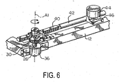
- Figs. 6-8 are perspective views of steering assemblies for independently steering wheelchair wheels.
- Figs. 9 and 10 are perspective views of assemblies for controlling movement of a wheelchair seat.
- Fig. 11 is a diagrammatic representation of a wheelchair drive wheel position sensor.
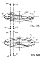
- Figs. 12A and 12B are diagrammatic representations of another wheelchair drive wheel position sensor.
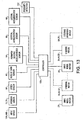
- Fig. 13 is a block diagram of a wheelchair control system.
- a chassis or base 12 which is supported for movement relative to a supporting surface (i.e., the ground or a floor) by a plurality of wheels 14a, 14b.
- a body or seat 16a, 16b (illustrated in Figs. 3-5) is adapted to be supported relative to the base 12.
- the seat 16a, 16b is provided for supporting an occupant (not shown).
- the base 12 is adapted for use in a wheelchair, which may be controlled by the occupant via an operator interface or input device 18a, 18b (illustrated in Figs. 3-5).
- the input device 18a, 18b may be, for example, in the form of a steering wheel, a joystick, a sip and puff control, or a head-movement device.
- the wheelchair is a power wheelchair, wherein one or more of the wheels 14a are driven (i.e., rotated about a horizontal axis) by a motor.
- the driven wheels 14a may be driven collectively by a single motor and a mechanical drive connection or linkage or transmission device, which mechanically attach the driven wheels 14a to one another for collective or coordinated motion.
- each driven wheel 14a may be driven independently by a separate motor 20, as illustrated in Figs. 2, 4, and 5.
- the driven wheel 14a and the motor 20 cooperatively form a drive wheel assembly, as generally indicated at 22.
- Each motor 20 is preferably a variable speed, bi-directional drive motor, and typically a DC motor, which rotatably drives a respective driven wheel 14a in forward and reverse directions.
- the motors 20 may be geared or otherwise connected to the driven wheels 14a in any of a number of known gearing or drive assemblies. It should be understood that no mechanical drive connection or linkage or transmission device mechanically attaches the driven wheels 14a to one another for collective or coordinated motion. Instead, coordinated motion is provided by a controller 100, which is described hereinbelow. It should also be understood that the lack or absence of a transmission device between the driven wheels 14a permits each driven wheel 14a to be pivotally rotated about a respective steering axis A1 in a complete 360-degree circle, without interference or impediment.
- Each wheel 14a, 14b may be collectively steered. This may be done in any suitable manner.
- each wheel 14a, 14b may have a stem 26 that has its upper end connected to a lever arm 28, as illustrated in Figs. 3 and 5.
- the stem 26 may have at its upper end a gear 30, as illustrated in Fig. 4.
- the lever arms 28 or gears 30 may be attached to a steering linkage 32a, 32b, 32c.
- the steering linkage 32a, 32b, 32c is adapted to keep the wheels 14a, 14b parallel to one another but allow simultaneous rotation of the driven wheel 14a.
- the steering linkage 32a, 32b, 32c may be driven by a steering motor 34 (illustrated in Figs. 4 and 5), which is attached to the base 12.
- the steering motor 34 is operable to cause each wheel 14a, 14b and the steering linkage 32a, 32b, 32c to rotate in unison, in the same direction and at equal angles. In this way, the wheels 14a, 14b may always be parallel to one another. Examples of such steering mechanisms are disclosed in U.S. Patents No. 5,139,279, issued August 18, 1992, 5,727,644, issued March 17, 1998, and 5,752,710, issued May 19, 1998, all to Brock E. Roberts, the disclosure of which is incorporated herein by reference.
- the wheels 14a, 14b may be independently steered. This may be accomplished in any suitable manner.
- the stem 26 of each wheel 14a, 14b may have a lower end that passes through a bearing 36, which is attached to the base 12, as illustrated in Fig. 6.
- the gear 30 connected to an upper end of the stem 26 may be toothed to cooperate with an elongated and similarly toothed drive rack 40.
- the drive rack 40 preferably has sufficient teeth to engage the gear 30 and to pivot the stem 26 through a full 360-degree rotation circle.
- the drive rack 40 may be, in turn, attached to a linear actuator shaft 42, which engages a linear drive motor 44 and optional gearing assembly that is mounted to the base 12 via a hold-down unit or clamp 46.
- the drive motor 44 may be a stepper or other DC bi-directional motor to enable selective linear advancement and retreat of the actuator shaft 42.
- the gear 30 moves and the stem 26 pivots to cause rotation of the wheel 14a, 14b about the axis A1 of the stem 26 in a clockwise or counterclockwise direction, as required for a particular motion of the base 12 along the supporting surface.
- the gear 30 carried at the upper end of the stem 26 may mesh with a toothed drive gear 48 which, via a depending shaft 50, is rotatable by a DC stepper motor 52 for pivoting the wheel 14a, 14b about the axis A1 of the stem 26, as illustrated in Fig. 7.
- the driven gear 30 and drive gear 48 form a gear train.
- each wheel 14a, 14b may be selectively latched and unlatched in fixed and pivotal relation to the base 12 and each wheel 14a, 14b may be offset from the axis A1 of rotation of the stem 26, as illustrated in Fig. 8.
- the wheel 14a, 14b may be unlatched and the motor 24, which may be the same motor that is used or operated to rotate the driven wheel 14a to move the base 12 along the supporting surface, may be driven to rotate the wheels 14a, 14b.
- the seat 16a and 16b as illustrated in Figs. 3-5, is supported for movement relative to the base 12. This may be accomplished in any suitable manner.
- the seat 16a, 16b may be attached to a central shaft 54 so that it is aligned parallel to the wheels 14a, 14b, and rotates with the central shaft 54.
- the input device 18a, 18b and controller 100 illustrated in Fig. 13, may direct the operation of the drive wheel assemblies 22 through a rotatable connection through the central shaft 54.
- the steering motors 34 operate to rotate the seat 16a, 16b, and each drive wheel assembly 22 in unison, in the same direction and at equal angles, keeping them in parallel.
- Activating the drive motors 20 moves the wheelchair forward and rearward in a straight line, or, if activated in conjunction with a steering motor 34, in a curve.
- Examples of such seats are disclosed in U.S. Patents No. 5,727,644, issued March 17, 1998, and 5,752,710, issued May 19, 1998, both to Brock E. Roberts.
- the mechanical linkage may be optionally or selectively mechanically coupled to the steering assembly to permit the wheels 14a, 14b to be steered without affecting the position of the seat 16a, 16b. This may be accomplished in any known manner, such as by toggling the seat 16a, 16b into and out of engagement with the steering linkage 32a, 32b, 32c.
- movement of the seat 16c is controlled by a drive assembly independent of that of the steering assembly.
- the seat 16c may be supported by a plate 56 having a gear 58 connected to its lower end and which is supported for rotation relative to the base 12 by a bearing (not shown).
- the gear 58 may be toothed to cooperate with an elongated and similarly toothed drive rack 60.
- the drive rack 60 preferably has sufficient teeth to engage the gear 58 and to pivot the plate 56 through a full 360-degree rotation circle.
- the drive rack 60 may be, in turn, attached to a linear actuator shaft 62, which engages a linear drive motor 64 and optional gearing assembly that is mounted to the base 12.
- the drive motor 64 may be a stepper or other DC bi-directional motor to enable selective linear advancement and retreat of the actuator shaft 62.
- the gear 58 moves and the plate 56 pivots to cause rotation of the seat 16c about the axis A1 in a clockwise or counterclockwise direction, independent of the position of the wheels 14a, 14b.
- the gear 58 connected to the plate 56 may mesh with a toothed drive gear 66 which, via a depending shaft 68, is rotatable by a DC stepper motor 70 for pivoting the seat 16c about the axis A1, as illustrated in Fig. 10.
- the driven gear 58 and drive gear 66 forms a gear train.
- the controller may interface with other various inputs (i.e., position sensors, speed sensors, rate-of-turn sensors, the accelerometer sensors, and the proximity detectors).
- the present invention may also include position sensors for sensing or determining and verifying the position of the wheels 14a, 14b.
- the position sensor may be, for example, in the form of a micro-switch 72, such as illustrated in Fig. 11.
- the micro-switch 72 may be provided for locating the home or zero position of the wheels 14a, 14b. Such a sensor would be suitable for use in conjunction with the drive rack 40 illustrated in Fig. 6.
- the micro-switch 72 includes a cam 74 that is substantially equal in length to and connected for movement with the drive rack 40.
- the micro-switch 72 has at its mid-point a transition slope connecting a thin width portion at one end of the cam 74 and a thick width portion at an opposite end of the cam 74.
- the micro-switch 72 is rigidly attached to the base 12 at a position such that the switch 72 lies at an actuatingly adjacent the longitudinal midpoint of the cam 74 when the wheels 14a, 14b are at zero positions. To "zero" the system during use of the wheelchair, the controller 100 is actuated and the zero position is found as follows:
- the wheel 14a, 14b must be located between 0 degrees and +180 degrees.
- the controller 100 therefore sends power to the linear drive motor 44 to move the drive rack 40 and the cam 74 to the right when viewing Fig. 11 until the micro-switch 72 closes.
- the wheel 14a, 14b has returned to its zero position, and movement by the actuator shaft 42 ceases.
- the controller 100 sends power to the linear drive motor 44 to move the drive rack 40 and the cam 74 to the left until the micro-switch 72 opens.
- the wheel 14a, 14b has returned to its zero position, and movement by the actuator shaft 42 ceases.
- FIG. 12A and 12B Another position sensor is illustrated in Figs. 12A and 12B.
- the sensor is useful for locating the home or zero position when a steering motor 44, 52 is used, as illustrated in Figs. 6 and 7.
- This position sensor includes a disc 76 having a slot 78, a hole 80, and two light sources 82, 84, which are aligned on opposite sides of the disc 76 with two phototransistors 86, 88.
- a first phototransistor 86 shines through the slot 78 and a circuit is completed.
- a second light source 84 shines therethrough and completes a circuit. Completion of the circuit connection through the hole 80 indicates the zero position for the wheel 14a, 14b, whereas circuit completion through the slot 78 indicates a non-zero position with rotation of the wheel 14a, 14b having proceeded through no more than 180 degrees.
- the slot 78 shown in Figs. 12A and 12B may alternatively be formed as a series of calibrated and spaced apart apertures, the spacing of which correlate with particular angular displacements of the wheels 14a, 14b.
- a counting system may be established with, for example, an additional phototransistor and light source and the controller, by summing the illuminations or flashes, which will at all times know or be able to determine the orientation of each wheel 14a, 14b.
- the present invention may also include tachometers or speed sensors 90 for sensing the rotational speed of the wheels 14a, 14b.
- the speed sensors 90 may be, for example, in the form of optical sensors, magnetic sensors (i.e., Hall effect sensors), or power delivery sensors, which sense power delivered to the wheels 14a, 14b, as illustrated in Fig. 13.
- the invention may further include a rate-of-turn sensor 92.
- the rate-of-turn sensor 92 may be provided for correcting the attitude, position or orientation of the wheelchair to prevent the wheelchair from drifting and ensure that the wheelchair tracks true.
- the rate-of-turn sensor 92 may be in the form of a piezoelectric ceramic gyroscope, similar to the Model CG-16D sensor manufactured and sold by Tokin America Corporation, or a conventional rotating gyroscope, or be constructed using properly orthogonally-oriented conventional linear accelerometer devices. In any event, it is preferred that rate-of-turn sensor 92 be able to measure wheelchair chassis angular rates of turn of at least 280 degrees per second to correspond to generally desired wheelchair turning rate capabilities. Such a rate-of-turn sensor 92 can be utilized by itself to control the turning of the wheelchair.
- the rate-of-turn sensor 92 is adapted to generate output signals to the controller 100 which correspond with that of the input device 18a, 18b.
- the controller 100 could function (e.g., via a time delay algorithm) to slow down a driven wheel 14a, as by applying dynamic or regenerative braking thereto, and/or optionally increase the speed of another driven wheel 14a.
- dynamic or regenerative braking action and/or, to a lesser extent, by increasing the rotational speed of a driven wheel stability of the wheelchair can be readily improved.
- accelerometer sensors 94, 96, 98 may be provided. Such sensors 94, 96, 98 may function to limit the turn rate of the wheelchair below a limit value and linear deceleration to below a limit value.
- the accelerometer sensors 94, 96, 98 may be installed physically within the confines or enclosure of the controller 100 or be remotely installed in the wheelchair provided that they have proper support and proper installation orthogonal orientation. By properly securing and orthogonally orienting the sensors 94, 96, 98 on the base 12, the sensors 94, 96, 98 function to detect and measure or indicate motorized wheelchair actual accelerations in orthogonal forward/reverse, vertical, and lateral directions, respectively.
- Front-wheel drive wheelchairs may tip forward if decelerated too quickly.
- Output signals from a forward/reverse accelerometer sensor 94 can be advantageously utilized by the controller 100 to anticipate and limit deceleration to a permissible rate that will ensure that the wheelchair will not tip forward when slowing, as for example, on a horizontal surface.
- the combination of the forward/reverse accelerometer sensor 94 and a vertical accelerometer sensor 96 can be used by the controller 100 to limit deceleration when going down a hill, slope, ramp, or the like. This can be accomplished by using a trigonometric algorithm calculation of the actual wheelchair forward inclination or tilt based on the wheelchair forward and vertical actual acceleration values.
- the controller 100 can place constraints on velocity and deceleration to ensure reliable and safe wheelchair operation through improved motion stability.
- top velocity can be limited as a function of a substantially flat surface, a slope, or a hill to establish a desired stopping distance subject to permissible deceleration rate as to prevent forward tipping of the wheelchair.
- a lateral accelerometer sensor 98 adds the ability to sense lateral movement of wheelchair.
- the forward/reverse accelerometer sensor 94 in combination with the lateral accelerometer sensor 98 can be utilized by the controller 100 to limit deceleration to a permissible rate, as when going around a turn to prevent the wheelchair from spinning-out and/or tipping.
- Such involves a trigonometric algorithmic calculation of the actual wheelchair lateral inclination or tilt based on both lateral and vertical actual acceleration values. This can be done by placing constraints or limits on velocity, deceleration, turning rate, and the like to insure reliable operation.
- a vertical accelerometer sensor adds the further ability to sense vertical movement as when moving down a slope, ramp, hill, or the like. This allows the controller to place necessary constraints on motion parameters that assure safe and reliable operation against spin-out and/or tipping, as on a hill.
- the present invention automatically corrects wheelchair veering when the wheelchair is traversing a sloped surface. For example, if the input device 18a, 18b demands a desired turn rate of zero but the rate-of- turn sensor 92 detects veering, then the controller 100 could automatically adjust the differential speed control to compensate for and zero out the veer.
- the present invention may additionally include proximity detectors 102 for sensing objects in the operating environment of the wheelchair.
- detectors 102 may be, for example, in the form of echo technology sensors (e.g., ultrasonic transducers), which sense the presence of objects about the wheelchair.
- the wheelchair within its controller 100 or otherwise, may have memory and have the ability to map an operating environment. In this way, the wheelchair can become familiar with certain areas within which it is operated and thus may possess the ability to control its operation with minimal commands from the wheelchair occupant.
Landscapes
- Engineering & Computer Science (AREA)
- Chemical & Material Sciences (AREA)
- Combustion & Propulsion (AREA)
- Transportation (AREA)
- Mechanical Engineering (AREA)
- Health & Medical Sciences (AREA)
- Life Sciences & Earth Sciences (AREA)
- Animal Behavior & Ethology (AREA)
- General Health & Medical Sciences (AREA)
- Public Health (AREA)
- Veterinary Medicine (AREA)
- Nursing (AREA)
- Motorcycle And Bicycle Frame (AREA)
- Handcart (AREA)
Applications Claiming Priority (2)
| Application Number | Priority Date | Filing Date | Title |
|---|---|---|---|
| US56560704P | 2004-04-27 | 2004-04-27 | |
| US565607P | 2004-04-27 |
Publications (2)
| Publication Number | Publication Date |
|---|---|
| EP1591092A2 true EP1591092A2 (de) | 2005-11-02 |
| EP1591092A3 EP1591092A3 (de) | 2005-12-28 |
Family
ID=34935813
Family Applications (1)
| Application Number | Title | Priority Date | Filing Date |
|---|---|---|---|
| EP05009212A Withdrawn EP1591092A3 (de) | 2004-04-27 | 2005-04-27 | Angetriebener Rollstuhl |
Country Status (2)
| Country | Link |
|---|---|
| US (1) | US20050236208A1 (de) |
| EP (1) | EP1591092A3 (de) |
Cited By (1)
| Publication number | Priority date | Publication date | Assignee | Title |
|---|---|---|---|---|
| US10864127B1 (en) | 2017-05-09 | 2020-12-15 | Pride Mobility Products Corporation | System and method for correcting steering of a vehicle |
Families Citing this family (58)
| Publication number | Priority date | Publication date | Assignee | Title |
|---|---|---|---|---|
| US7275607B2 (en) | 1999-06-04 | 2007-10-02 | Deka Products Limited Partnership | Control of a personal transporter based on user position |
| US7210544B2 (en) | 2002-07-12 | 2007-05-01 | Deka Products Limited Partnership | Control of a transporter based on attitude |
| US20070114742A1 (en) * | 2005-07-29 | 2007-05-24 | Gilbert Roger A | Motorized carts for stepping structures |
| WO2007027846A2 (en) * | 2005-08-31 | 2007-03-08 | Invacare Corporation | Method and apparatus for automated positioning of user support surfaces in power driven wheelchair |
| US7403844B2 (en) | 2005-08-31 | 2008-07-22 | Invacare Corporation | Method and apparatus for programming parameters of a power driven wheelchair for a plurality of drive settings |
| US20070050096A1 (en) * | 2005-08-31 | 2007-03-01 | Invacare Corporation | Programmable actuator controller for power positioning seat or leg support of a wheelchair |
| US7597160B2 (en) * | 2005-09-07 | 2009-10-06 | Lawson Jr Thomas Towles | Four wheel drive system |
| GB2437503A (en) * | 2006-04-24 | 2007-10-31 | Advanced Transp Systems Ltd | Steering arrangement using differing drive torques |
| WO2008065686A2 (en) * | 2006-12-01 | 2008-06-05 | Mp S.R.L. | Self moving cart for invalids, and method for managing said cart in business centres or other specific areas |
| US20090038864A1 (en) * | 2007-08-07 | 2009-02-12 | Sung Yol Yun | Remotely controllable golf cart and method for steering a cart |
| US20110257900A1 (en) * | 2008-09-22 | 2011-10-20 | Purdue Research Foundation | Methods and apparatus for diagnosing faults of a vehicle |
| CN102458962B (zh) * | 2009-06-19 | 2014-10-29 | 国立大学法人丰桥技术科学大学 | 能够转向的驱动机构及全方向移动车 |
| GB2486179B (en) * | 2010-12-03 | 2014-12-17 | Penny & Giles Controls Ltd | Front wheel drive motorised vehicle control using acceleration measurements |
| NZ592381A (en) * | 2011-04-20 | 2013-07-26 | Dynamic Controls | Steering control system for a manual wheelchair for maintaining straight line path of travel |
| ES2901153T3 (es) | 2011-07-06 | 2022-03-21 | Max Mobility Llc | Sistema de asistencia de accionamiento energético basado en el movimiento para sillas de ruedas |
| US9259369B2 (en) | 2012-09-18 | 2016-02-16 | Stryker Corporation | Powered patient support apparatus |
| US10004651B2 (en) * | 2012-09-18 | 2018-06-26 | Stryker Corporation | Patient support apparatus |
| US9144525B2 (en) | 2013-03-14 | 2015-09-29 | Max Mobility, Llc. | Motion assistance system for wheelchairs |
| GB2529286B (en) | 2013-05-20 | 2017-11-01 | Sevcon Ltd | Vehicle controller and method of controlling a vehicle |
| CN103963637B (zh) * | 2014-04-29 | 2017-08-25 | 浙江吉利控股集团有限公司 | 一种用于车辆的整体式转向驱动桥和电动车辆 |
| US9795524B2 (en) | 2015-02-24 | 2017-10-24 | Max Mobility, Llc | Assistive driving system for a wheelchair |
| US20160257340A1 (en) * | 2015-03-03 | 2016-09-08 | Kan Cui | Simultaneous actuating mechanism for parallel axis rotors |
| US10406045B2 (en) | 2015-06-22 | 2019-09-10 | Stryker Corporation | Patient support apparatuses with navigation and guidance systems |
| US10406044B2 (en) | 2015-06-25 | 2019-09-10 | Stryker Corporation | Person support apparatuses with drive controls |
| US9724253B2 (en) | 2015-08-11 | 2017-08-08 | Brian M. Watwood | Foot operated mechanical steering system for a manual wheelchair |
| US10568792B2 (en) * | 2015-10-28 | 2020-02-25 | Stryker Corporation | Systems and methods for facilitating movement of a patient transport apparatus |
| US10045893B2 (en) | 2015-12-22 | 2018-08-14 | Stryker Corporation | Patient transport apparatus with controllable auxiliary wheel assembly |
| US10908045B2 (en) | 2016-02-23 | 2021-02-02 | Deka Products Limited Partnership | Mobility device |
| US10926756B2 (en) | 2016-02-23 | 2021-02-23 | Deka Products Limited Partnership | Mobility device |
| CA3278463A1 (en) | 2016-02-23 | 2025-10-27 | Deka Products Limited Partnership | Mobility device control system |
| US11399995B2 (en) | 2016-02-23 | 2022-08-02 | Deka Products Limited Partnership | Mobility device |
| US10603234B2 (en) | 2016-03-30 | 2020-03-31 | Stryker Corporation | Patient support apparatuses with drive systems |
| EP3443426B1 (de) | 2016-04-14 | 2022-10-26 | DEKA Products Limited Partnership | Ein transporter und ein verfahren zur steuerung eines transporters |
| CN105882784B (zh) * | 2016-05-27 | 2021-08-17 | 中国科学院宁波材料技术与工程研究所 | 全向移动平台及其动力万向轮 |
| US10384531B2 (en) * | 2016-06-04 | 2019-08-20 | Chun-Hsiang Yang | Universal wheel |
| NL2017105B1 (en) * | 2016-07-05 | 2018-01-12 | Lely Patent Nv | Vehicle |
| CN108612818B (zh) * | 2016-12-13 | 2023-02-03 | 崔侃 | 平行轴线转动的同步驱动机构 |
| AT519463B1 (de) * | 2017-01-28 | 2018-07-15 | Fahrwerk | |
| US9789902B1 (en) | 2017-04-05 | 2017-10-17 | Kan Cui | Simultaneous manuvering system for vehicles |
| CN106945748B (zh) * | 2017-04-26 | 2023-10-13 | 安徽工程大学 | 底盘总成及具有其的机器人和探测车辆 |
| CN107160963B (zh) * | 2017-05-04 | 2020-08-21 | 大陆智源科技(北京)有限公司 | 轮式运动底盘 |
| USD1047785S1 (en) | 2017-05-20 | 2024-10-22 | Deka Products Limited Partnership | Toggle control device |
| USD829612S1 (en) | 2017-05-20 | 2018-10-02 | Deka Products Limited Partnership | Set of toggles |
| USD846452S1 (en) | 2017-05-20 | 2019-04-23 | Deka Products Limited Partnership | Display housing |
| US10167051B1 (en) | 2017-12-12 | 2019-01-01 | Max Mobility, Llc | Assistive driving system for a wheelchair and method for controlling assistive driving system |
| WO2019157511A1 (en) * | 2018-02-12 | 2019-08-15 | Crosby Kelvin | Robotic sighted guiding system |
| JP2021527204A (ja) | 2018-06-07 | 2021-10-11 | デカ・プロダクツ・リミテッド・パートナーシップ | 配送多目的サービス実行のためのシステムおよび方法 |
| CN108516013A (zh) * | 2018-06-12 | 2018-09-11 | 太原科技大学 | 一种轨道式四轮驱动电动汽车独立转向装置 |
| CN110509781A (zh) * | 2019-08-13 | 2019-11-29 | 深兰科技(上海)有限公司 | 一种控制移动设备行进的方法及装置 |
| JP7479146B2 (ja) * | 2019-12-25 | 2024-05-08 | ナブテスコ株式会社 | 電気制御車両 |
| US11890234B2 (en) * | 2019-12-30 | 2024-02-06 | Stryker Corporation | Patient transport apparatus with crash detection |
| US12162527B2 (en) * | 2021-04-20 | 2024-12-10 | Nsk Ltd. | Drive wheel and cart |
| US11130519B1 (en) | 2021-05-18 | 2021-09-28 | Kan Cui | Parallel maneuvering system |
| US11414128B1 (en) | 2021-08-09 | 2022-08-16 | Kan Cui | Multiple maneuvering systems for various applications |
| CN114931473B (zh) * | 2022-05-17 | 2023-12-19 | 南京工程学院 | 一种轮椅万向轮自动解锁系统及控制方法 |
| US12083059B1 (en) * | 2023-04-11 | 2024-09-10 | Clyde Stephen Ledbetter | Universal steering system |
| CN121219188A (zh) * | 2023-04-13 | 2025-12-26 | 格雷戈里·詹姆斯·纽维 | 可调节的位移式差速驱动系统 |
| CN116654099B (zh) * | 2023-06-28 | 2025-08-05 | 东北大学 | 双曲柄连杆十字滑块式全方位移动底盘结构及控制方法 |
Citations (6)
| Publication number | Priority date | Publication date | Assignee | Title |
|---|---|---|---|---|
| US5139279A (en) | 1990-10-10 | 1992-08-18 | Roberts Brock F | Parallel-aligned all-wheel steered vehicle |
| US5547038A (en) | 1991-08-01 | 1996-08-20 | Madwed; Albert | Wheeled chassis having independently pivotable drivewheels for omnidirectional motion |
| US5727644A (en) | 1995-07-17 | 1998-03-17 | Roberts; Brock F. | Parallel-aligned all-wheel steered vehicle II |
| US5752710A (en) | 1996-07-05 | 1998-05-19 | Roberts; Brock F. | Parallel-aligned all-wheel steered vehicle III |
| US6109379A (en) | 1997-07-25 | 2000-08-29 | Madwed; Albert | Independently pivotable drivewheel for a wheeled chassis |
| US6202773B1 (en) | 1999-07-30 | 2001-03-20 | Invacare Corporation | Motorized wheelchairs |
Family Cites Families (13)
| Publication number | Priority date | Publication date | Assignee | Title |
|---|---|---|---|---|
| US1557833A (en) * | 1922-09-05 | 1925-10-20 | Albert James Owen | Hand-propelled truck, trolley, and the like |
| US3572458A (en) * | 1968-12-10 | 1971-03-30 | Hans Tax | All-wheel steering system |
| GB1440672A (en) * | 1973-02-06 | 1976-06-23 | Digitron Ag | Transport vehicles and transport systems utilising such vehicles |
| US3972379A (en) * | 1975-03-11 | 1976-08-03 | Norris Charlie L | Hydrostatically driven vehicle |
| US4044853A (en) * | 1976-04-05 | 1977-08-30 | Jervis B. Webb Company | Driverless vehicle and guidance system |
| US4274503A (en) * | 1979-09-24 | 1981-06-23 | Charles Mackintosh | Power operated wheelchair |
| US4444287A (en) * | 1980-11-28 | 1984-04-24 | Renner Manufacturing Company | Steering system for mobile crane |
| US4483405A (en) * | 1981-08-05 | 1984-11-20 | Koyu Enterprise, Inc. | Omnidirectional motorized wheelchair |
| GB2184988B (en) * | 1985-12-16 | 1989-01-05 | Jeremy Joseph Fry | Wheelchair steering |
| US6510981B1 (en) * | 1999-06-09 | 2003-01-28 | General Mills, Inc. | Canister with paper and plastic layers and a plastic lid for containing a particulate-type product, such as a ready-to-eat cereal |
| US6615937B2 (en) * | 1999-07-30 | 2003-09-09 | Invacare Corporation | Motorized wheelchairs |
| US6526336B2 (en) * | 2001-02-01 | 2003-02-25 | Invacare Corp. | System and method for steering a multi-wheel drive vehicle |
| JP4178955B2 (ja) * | 2001-04-20 | 2008-11-12 | セイコーエプソン株式会社 | 駆動制御 |
-
2005
- 2005-04-27 US US11/115,568 patent/US20050236208A1/en not_active Abandoned
- 2005-04-27 EP EP05009212A patent/EP1591092A3/de not_active Withdrawn
Patent Citations (6)
| Publication number | Priority date | Publication date | Assignee | Title |
|---|---|---|---|---|
| US5139279A (en) | 1990-10-10 | 1992-08-18 | Roberts Brock F | Parallel-aligned all-wheel steered vehicle |
| US5547038A (en) | 1991-08-01 | 1996-08-20 | Madwed; Albert | Wheeled chassis having independently pivotable drivewheels for omnidirectional motion |
| US5727644A (en) | 1995-07-17 | 1998-03-17 | Roberts; Brock F. | Parallel-aligned all-wheel steered vehicle II |
| US5752710A (en) | 1996-07-05 | 1998-05-19 | Roberts; Brock F. | Parallel-aligned all-wheel steered vehicle III |
| US6109379A (en) | 1997-07-25 | 2000-08-29 | Madwed; Albert | Independently pivotable drivewheel for a wheeled chassis |
| US6202773B1 (en) | 1999-07-30 | 2001-03-20 | Invacare Corporation | Motorized wheelchairs |
Cited By (1)
| Publication number | Priority date | Publication date | Assignee | Title |
|---|---|---|---|---|
| US10864127B1 (en) | 2017-05-09 | 2020-12-15 | Pride Mobility Products Corporation | System and method for correcting steering of a vehicle |
Also Published As
| Publication number | Publication date |
|---|---|
| US20050236208A1 (en) | 2005-10-27 |
| EP1591092A3 (de) | 2005-12-28 |
Similar Documents
| Publication | Publication Date | Title |
|---|---|---|
| EP1591092A2 (de) | Angetriebener Rollstuhl | |
| US6109379A (en) | Independently pivotable drivewheel for a wheeled chassis | |
| US8011459B2 (en) | Inverted wheel type moving body and method of controlling same | |
| EP1940718B1 (de) | Neigungsaufzugseinheit und neigungsaufzug | |
| US6615937B2 (en) | Motorized wheelchairs | |
| ES2493393T3 (es) | Método para teleoperar un vehículo terrestre no tripulado con una cámara con desplazamiento horizontal y tal vehículo terrestre | |
| BRPI0711467A2 (pt) | máquina para silvicultura , e, método para controlar a mesma | |
| EP1972486A1 (de) | Motorisierter Rollstuhl | |
| JP2769636B2 (ja) | 無人自走車 | |
| AU5788200A (en) | Motorized wheelchairs | |
| US4815319A (en) | System for determining the movement of a track vehicle | |
| JP6400174B1 (ja) | 走行装置 | |
| JP4078889B2 (ja) | 電動車椅子 | |
| US6708580B1 (en) | Device for controlling an apparatus | |
| WO2021155465A1 (en) | Inclination control system for tracked vehicle | |
| CN1651331A (zh) | 地面输送机的控制手柄头部、地面输送机及操作该机的方法 | |
| WO2018128951A1 (en) | Vehicle steering system | |
| CN110420097A (zh) | 一种电动轮椅的微动控制系统 | |
| JPH02285114A (ja) | 車輛の走行制御装置およびその制御方法 | |
| US11989036B2 (en) | Vehicle with communicative behaviors | |
| EP1762464A1 (de) | Verfahren zur Nachlaufführung | |
| JPS6038240B2 (ja) | 自走台車 | |
| JPH06344944A (ja) | 傾斜地走行車輌 | |
| JPH0332944A (ja) | ヘッドライト駆動装置 | |
| JP4882514B2 (ja) | 倒立車輪型の移動体及びその制御方法 |
Legal Events
| Date | Code | Title | Description |
|---|---|---|---|
| PUAI | Public reference made under article 153(3) epc to a published international application that has entered the european phase |
Free format text: ORIGINAL CODE: 0009012 |
|
| AK | Designated contracting states |
Kind code of ref document: A2 Designated state(s): AT BE BG CH CY CZ DE DK EE ES FI FR GB GR HU IE IS IT LI LT LU MC NL PL PT RO SE SI SK TR |
|
| AX | Request for extension of the european patent |
Extension state: AL BA HR LV MK YU |
|
| PUAL | Search report despatched |
Free format text: ORIGINAL CODE: 0009013 |
|
| AK | Designated contracting states |
Kind code of ref document: A3 Designated state(s): AT BE BG CH CY CZ DE DK EE ES FI FR GB GR HU IE IS IT LI LT LU MC NL PL PT RO SE SI SK TR |
|
| AX | Request for extension of the european patent |
Extension state: AL BA HR LV MK YU |
|
| 17P | Request for examination filed |
Effective date: 20060613 |
|
| AKX | Designation fees paid |
Designated state(s): AT BE BG CH CY CZ DE DK EE ES FI FR GB GR HU IE IS IT LI LT LU MC NL PL PT RO SE SI SK TR |
|
| STAA | Information on the status of an ep patent application or granted ep patent |
Free format text: STATUS: THE APPLICATION HAS BEEN WITHDRAWN |
|
| 18W | Application withdrawn |
Effective date: 20070315 |