EP1600701A2 - Systeme de conditionnement d'air et de generation d'energie electrique - Google Patents
Systeme de conditionnement d'air et de generation d'energie electrique Download PDFInfo
- Publication number
- EP1600701A2 EP1600701A2 EP05011300A EP05011300A EP1600701A2 EP 1600701 A2 EP1600701 A2 EP 1600701A2 EP 05011300 A EP05011300 A EP 05011300A EP 05011300 A EP05011300 A EP 05011300A EP 1600701 A2 EP1600701 A2 EP 1600701A2
- Authority
- EP
- European Patent Office
- Prior art keywords
- engine
- air
- conditioning
- ratio
- rotator
- Prior art date
- Legal status (The legal status is an assumption and is not a legal conclusion. Google has not performed a legal analysis and makes no representation as to the accuracy of the status listed.)
- Withdrawn
Links
- 238000004378 air conditioning Methods 0.000 title claims abstract description 73
- 238000010438 heat treatment Methods 0.000 claims abstract description 59
- 238000001816 cooling Methods 0.000 claims abstract description 36
- XLYOFNOQVPJJNP-UHFFFAOYSA-N water Substances O XLYOFNOQVPJJNP-UHFFFAOYSA-N 0.000 claims description 48
- 239000000446 fuel Substances 0.000 claims description 28
- 230000001965 increasing effect Effects 0.000 claims description 11
- 239000007789 gas Substances 0.000 claims description 9
- 239000002918 waste heat Substances 0.000 claims description 7
- 230000003213 activating effect Effects 0.000 claims description 6
- 230000003247 decreasing effect Effects 0.000 claims description 3
- 230000004913 activation Effects 0.000 description 11
- 239000002826 coolant Substances 0.000 description 9
- 238000010586 diagram Methods 0.000 description 4
- 238000009423 ventilation Methods 0.000 description 4
- 230000000694 effects Effects 0.000 description 3
- 230000002708 enhancing effect Effects 0.000 description 3
- 238000011084 recovery Methods 0.000 description 3
- 239000003990 capacitor Substances 0.000 description 2
- 230000007423 decrease Effects 0.000 description 2
- 239000007858 starting material Substances 0.000 description 2
- 230000007812 deficiency Effects 0.000 description 1
- 230000002542 deteriorative effect Effects 0.000 description 1
- 230000002349 favourable effect Effects 0.000 description 1
- 239000007788 liquid Substances 0.000 description 1
- 239000003507 refrigerant Substances 0.000 description 1
- 230000000153 supplemental effect Effects 0.000 description 1
- 238000010792 warming Methods 0.000 description 1
- 239000002699 waste material Substances 0.000 description 1
Images


Classifications
-
- F—MECHANICAL ENGINEERING; LIGHTING; HEATING; WEAPONS; BLASTING
- F25—REFRIGERATION OR COOLING; COMBINED HEATING AND REFRIGERATION SYSTEMS; HEAT PUMP SYSTEMS; MANUFACTURE OR STORAGE OF ICE; LIQUEFACTION SOLIDIFICATION OF GASES
- F25B—REFRIGERATION MACHINES, PLANTS OR SYSTEMS; COMBINED HEATING AND REFRIGERATION SYSTEMS; HEAT PUMP SYSTEMS
- F25B27/00—Machines, plants or systems, using particular sources of energy
-
- F—MECHANICAL ENGINEERING; LIGHTING; HEATING; WEAPONS; BLASTING
- F24—HEATING; RANGES; VENTILATING
- F24F—AIR-CONDITIONING; AIR-HUMIDIFICATION; VENTILATION; USE OF AIR CURRENTS FOR SCREENING
- F24F5/00—Air-conditioning systems or apparatus not covered by F24F1/00 or F24F3/00, e.g. using solar heat or combined with household units such as an oven or water heater
- F24F5/0007—Air-conditioning systems or apparatus not covered by F24F1/00 or F24F3/00, e.g. using solar heat or combined with household units such as an oven or water heater cooling apparatus specially adapted for use in air-conditioning
-
- Y—GENERAL TAGGING OF NEW TECHNOLOGICAL DEVELOPMENTS; GENERAL TAGGING OF CROSS-SECTIONAL TECHNOLOGIES SPANNING OVER SEVERAL SECTIONS OF THE IPC; TECHNICAL SUBJECTS COVERED BY FORMER USPC CROSS-REFERENCE ART COLLECTIONS [XRACs] AND DIGESTS
- Y02—TECHNOLOGIES OR APPLICATIONS FOR MITIGATION OR ADAPTATION AGAINST CLIMATE CHANGE
- Y02E—REDUCTION OF GREENHOUSE GAS [GHG] EMISSIONS, RELATED TO ENERGY GENERATION, TRANSMISSION OR DISTRIBUTION
- Y02E20/00—Combustion technologies with mitigation potential
- Y02E20/14—Combined heat and power generation [CHP]
Definitions
- This invention generally relates to an air-conditioning and electric energy generating system according to which both an air conditioner-driving device, such as a compressor, which drives an air conditioner for ventilation and air-conditioning, and an electric generator which generates electric energy.
- an air conditioner-driving device such as a compressor
- an electric generator which generates electric energy.
- JP2002-257431A discloses a cogeneration system, which incorporates, therein, an engine, a compressor that drives an air conditioner for ventilation, an electric generator that generates electrical energy, and a casing that houses these components integrally therein.
- JP2000-337231A discloses a system which incorporates, therein, a compressor that drives an air conditioner for air-conditioning, a electrical generator that generates electrical energy and operates as a motor, an engine linked to the electrical generator, a rotor position-detecting sensor for detecting a position of a rotor of the electrical generator, a brushless motor circuit which electrically excites, on the basis of a signal of the rotor position-detecting sensor, coils of the electrical generator in such a manner of producing a rotational magnetic field at the coils, a direct-current power source that supplies electric voltage to the brushless motor circuit, and an inverter circuit that converts energy output from the electrical generator to alternate-current output.
- the electrical generator is provided as a single unit and can function, not only as an electric generator, but also as a starter motor for starting up activation of an engine. Moreover, this electrical generator is controlled to generate energy output in response to variations in load applied to the compressor as an air conditioner-driving device, thereby enabling to confine a degree of load imposed on an engine to a certain definite value.
- a driving force of an engine is distributed to both the compressor for driving the air conditioner and the electric generator.
- Percentages, at which the driving force of the engine is distributed to both the compressor and the electric generator, are basically fixed. Therefore, there may be a certain ceiling to further improve both air-conditioning performance by the air conditioner and electrical energy generating performance by the electric generator.
- the electrical generator is provided as a single unit and can function, not only as an electric generator, but also as a starter motor for starting up activation of an engine. Therefore, the compressor and the electric generator are not provided separately from each other. Further, the compressor and the electric generator are not operated simultaneously by the engine. That is, both ventilation (air-conditioning) and generation of electric energy are not implemented simultaneously.
- the present invention has been made in view of the above circumstances, and provides an air-conditioning and electric energy generating system, in which both an air-conditioner driving device such as a compressor and a electric generator are driven independently, and in which air-conditioning performance by an air-conditioner and electric energy generating performance by an electric generator can be effectively enhanced.
- an air-conditioning and electric energy generating system includes an engine producing a driving force, an air conditioner having at least one of cooling and heating abilities; an air conditioner-driving device for driving the air conditioner, an electrical generator for generating electrical energy, and a driving force distributing means provided between the air conditioner-driving device and the electrical generator and for distributing the driving force from the engine to the air conditioner-driving device and the electric generator at variable first and second ratios, respectively.
- the air-conditioning and electric energy generating system further includes a driving force distribution ratio controlling means by which the second ratio is controlled to a relatively low extent when the first ratio is relatively high, and the second ratio is controlled to a relatively high extent when the first ratio is relatively low.
- the driving force distribution ratio controlling means controls the first ratio and the second ratio depending on at least one of thermal energy information on thermal energy accumulated in a water storage tank, air-conditioning load information required to the air conditioner, and required electric energy amount information on a requisite amount of electric power to be generated.
- Fig. 1 is a block view schematically illustrating an air-conditioning and electric energy generating system according to an embodiment of the present invention
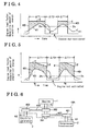
- Fig. 2 is a diagram for explaining variations in an engine load factor and in engine driving force distribution ratios when cooling is demanded;
- Fig. 3 is a diagram for explaining variations in the engine load factor and in the engine driving force distribution ratios when heating is demanded;
- Fig. 4 is a diagram for explaining variations in the engine load factor and in a requisite amount of electric power to be generated when neither cooling nor heating is demanded;
- Fig. 5 is another diagram for explaining the variations in the engine load factor and in a requisite amount of electric power to be generated when neither cooling nor heating is demanded;
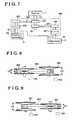
- Fig. 6 is a block view schematically illustrating a linkage among an engine, a compressor and an electric generator
- Fig. 7 is a block view schematically illustrating another linkage among the engine, the compressor and the electric generator;
- Fig. 8 is a view illustrating a relevant portion of a driving force distributing means according to the embodiment of the present invention.
- Fig. 9 is another view illustrating a relevant portion of the driving force distributing means according to the embodiment of the present invention.
- an air-conditioning and electric energy generating system incorporates, therein, an engine 1, for example a gas engine which consumes combustible gas as a fuel, a compressor 2, which serves as an air conditioner-driving device for driving an air conditioner 8 (operated for at least one of cooling and heating) furnished at a building 100 (e.g., a residential building, a building, and a movable body), inter alia, for the purpose of ventilation or air-conditioning, and an electrical generator 3 that generates electrical energy.
- the engine 1 is a driving source that is shared by both the compressor 2 and the electrical generator 3, and it is the only source of each of them.
- the engine 1 is activated by consuming combustible liquid or gas as fuel, and can be represented by a gasoline engine, a diesel engine, a reciprocal engine, and a rotary engine, as non-limiting examples.
- This air-conditioning and electric energy generating system further incorporates, therein, a storage battery 4 (including a capacitor), which stores an excessive amount of electrical energy generated by the electrical generator 3, an inverter 5, which converts a current flow of direct current into a current flow of alternate current, and then supplies the alternate current to an electric power consuming unit 110 of the building 100, an engine waste heat recovery unit 6 recovering waste heat of the engine 1 as hot water or steam through a thermal exchange therein, a water storage tank 7 connected to the engine waste heart recovery unit 6, the air conditioner 8, which is controlled, on the basis of a refrigerant compressed by the compressor, to heat and cool an inside of the building 100, an inside of a room of the building 100, and an operating panel 9 on which a user manually sets conditions for operating this air-conditioning and electric energy generating system.
- a storage battery 4 including a capacitor
- an inverter 5 which converts a current flow of direct current into a current flow of alternate current, and then supplies the alternate current to an electric power consuming unit 110 of the building
- the air conditioner 8 implements either cooling or heating in response to operation of a switch 91.
- the engine waste heat recovery unit 6 is configured with: a coolant passage 60 in which an engine coolant for refrigerating the engine 1 flows; a heat exchanger 61 communicating with the coolant passage 60; a circulation passage 63 communicating with the water storage tank 7 for storing, therein, water heated up through a thermal exchange, a water feeding source 64a (e.g., a pump) provided at the coolant passage 60; and a water feeding source 64b (e.g., a pump) provided at the circulation passage 63.
- An engine coolant can be circulated through the coolant passage 60 by the water feeding source 64a, therefore.
- the engine coolant can hence be heated up by recovering the waste heat of the engine 1 and can flow through a first passage 61 f of the heat exchanger 61.
- thermal exchange can be efficiently implemented especially between water flowing in a second passage 61s and the engine coolant flowing in the first passage 61f, wherein the water in the second passage 61s is heated up by the engine coolant in the first passage 61f, and is stored as hot water in the water storage tank 7 after flowing the circulation passage 63.
- the hot water accumulated in the water storage tank 7 is supplied to both a hot water heater 71 (e.g., hot water heaters for a bath, a shower and a kitchen) furnished at the building 100 and a floor heating appliance 72 for heating a floor of the building 100.
- supplemental water is fed into the water storage tank 7 via a water supply port 7m.
- a driving force distributing means 10 is installed between the compressor and the electrical generator 3.
- the driving force distributing means 10 the engine 1, the compressor 2 and the electrical generator 3 are interconnected.
- driving force emanated from the engine 1 can be transmitted to both the compressor 2 and the electrical generator 3 for their individual operations.
- the driving force distributing means 10 can alter by gradual steps or continuously a first ratio R1, at which the driving force of the engine 1 is distributed to the compressor 2, and a second ratio R2, at which the driving force of the engine 1 is distributed to the electrical generator 3.
- the first ratio R1 is designed by gradual steps or continuously to alter from 0 to 100% inclusive.
- the second ratio R1 is designed to alter by gradual steps or continuously from 0 to 100% inclusive.
- This air-conditioning and electric energy generating system further incorporates, therein, a controller 90 for controlling this system.
- the controller 90 can act as a driving force distribution controlling means for controlling driving of the driving force distributing means 10, an engine controlling means for controlling activation of the engine 1, and an electrical energy controlling means for controlling an excessive amount of electrical energy generated by the electrical generator 3 either to be accumulated in the storage battery (4) or to be transmitted to commercial electric wires.
- the controller 90 is inputted with thermal energy information S 1 which represents thermal energy already accumulated in the water storage tank 7, air-conditioning load information S2 on a degree of air-conditioning load required to the air conditioner 8 (at least one of cooling and heating), and required electric energy amount information S3 which represents a requisite amount of electric power to be generated (electric power consumption) that is currently being consumed by the electric power consuming unit 110 of a residential building, a building and so on.
- the controller 90 outputs, on the basis of the thermal energy information S1, the air-conditioning load information S2 and the required electric energy amount information S3, a signal Se controlling activation of the engine 1 and a signal Sd controlling the driving force distributing means 10.
- the controller 90 preferably controls, on the basis of at least one of the information S1, S2 and S3, the driving force-distributing means 10 to alter respective degrees of the first ratio R1 and the second ratio R2.
- thermal energy information S1 on the thermal energy stored in the water storage tank 7 at least one of a temperature of hot water stored in the water storage tank 7 and the amount of hot water therein is referred to.
- a temperature of hot water is obtained by a hot water temperature sensor 73, which is equipped to the water storage tank 7 and detects a temperature of the hot water accumulated in the water storage tank 7.
- the amount of hot water accumulated in the water storage tank 7 is obtained by a hot water amount sensor 74, which is also equipped to the water storage tank 7 and detects the amount of hot water already stored in the water storage tank 7.
- air-conditioning load information S2 which is employed so as to set a degree of load applied to the air conditioner 8, at least one of an ambient temperature of the building 100 and a humidity thereof is referred to.
- An ambient temperature of the building 100 is obtained on the basis of a thermal requirement signal determined by a temperature switch 81 furnished in the operating panel 9, while a humidity is obtained on the basis of a humidity requirement signal determined by a humidity switch 82 furnished therein.
- the required electric energy amount information S3 is obtained by a wattmeter 111 furnished at the building 100.
- the air conditioner 8 When cooling or heating is highly required, such as when an outside air temperature is relatively high or low, the air conditioner 8 on occasions is subjected to air-conditioning load that is greater than that required when an outside air temperature falls within an appropriate temperature range.
- the controller 90 in such circumstances sets a degree of driving force from the engine 1.
- the controller 90 further performs a second distribution control by which the first ratio R1, at which the driving force of the engine 1 is distributed to the compressor 2, is relatively high, and the second ratio R2, at which the driving force of the engine 1 is distributed to the electrical generator 3, is relatively low. Therefore, by reducing the percentage, at which electrical energy is generated, together with increasing the percentage, at which air-conditioning is performed, as described above, cooling or heating can be appropriately achieved.
- the air conditioner 8 when cooling or heating is less required, such as when an outside air temperature is appropriate, the air conditioner 8 is subjected to air-conditioning load that is relatively small, or is not subjected to such load.
- the controller 90 performs a first distribution control by which the first ratio R1 is relatively low, or is controlled to zero percentage, thereby lowering a rotational speed of the compressor 2, or controlling the compressor 2 not to rotate.
- the controller 90 raises the second ratio R2, at which the driving force of the engine 1 is distributed to the electrical generator 3, whereby increasing an amount of electrical energy generated by the electrical generator 3.
- the electrical generator 3 there may be a danger of the electrical generator 3 of generating an amount of electrical energy, which is greater than an amount of electric power consumed by the electric power-consuming unit 110. If the electrical generator 3 generates such a great amount of electrical energy, an excessive amount of electric energy can be stored in the storage battery 4.
- a value of the first ratio R1 is expressed as a relative value.
- the first ratio R1 is relatively high, it means that the first ratio R1 is relatively higher than that which is low.
- the first ratio R1 is relatively low, it means that the first ratio R1 is relatively lower than that which is high.
- the first ratio R1 can be expressed on the basis of whether the first ratio R1 is higher or lower than a threshold value.
- the second ratio R2 at which the driving force of the engine 1 is distributed to the electrical generator 3, is relatively lowered.
- the first ratio R1, at which the driving force of the engine 1 is distributed to the compressor 2 is relatively lowered
- the second ratio R2, at which the driving force of the engine 1 is distributed to the electrical generator 3, is relatively raised.
- An engine load factor herein refers to a percentage of a load currently applied to an engine on an assumption that a rated load of an engine is 100%. When the engine load factor is 90%, the engine is being applied with load that is 90% relative to the rated load of an engine.
- the engine load factor can be confined to within the definite ratio, it is possible to keep a fuel efficiency of the engine 1 at an appropriate level, thereby enabling to reduce a cost for fuel for activating the engine 1. Still moreover, in order to improve a fuel efficiency of the engine 1, it is preferable that the engine load factor is confined to the predetermined ratio or more, and to within the definite ratio range. In general, frequent variations in the engine load factor, and engine activation with the engine load factor confined to a low ratio on occasions deteriorate the fuel efficiency of the engine 1. Therefore, at least these two factors are deemed to be not favorable in terms of fuel efficiency of the engine 1. In other words, variations in the engine load factor, which occur less often, is more preferable, inter alia, for the purpose of enhancing the fuel efficiency of the engine 1.
- Table 1 shows one of examples concerning about distribution of the driving force of the engine 1.
- Primary control Air-conditioning or Electric energy generation
- Air-conditioning ⁇ Electric energy generation
- R1 (%) 100 90 80 70 60 30 20 10 0 R2 (%) 0 10 20 30 40 70 80 90 100 Total (%) 100 100 100 100 100 100 100 100 100 100 100 100 100 100 100 100 100 100 100 100 100 100 100 100 100 100 100 100 100 100 100 100 100 100 100 100 100 100 100
- the total percentage of the first and second ratios R1 and R2 is relatively determined to be 100%
- the total percentage is primarily dominated by the first ratio R1, which is controlled to a high degree, rather than the second ratio R2, which is controlled to a low degree.
- the total percentage is primarily dominated by the second ratio R2, which is controlled to a high degree, rather than the first ratio, which is controlled to a low degree.
- the total percentage of the first and second ratios R1 and R2 can be relatively determined to be 70%.
- Primary control Air-conditioning or Electric energy generation
- Air-conditioning ⁇ Electric energy generation
- the total percentage is primarily dominated by the first ratio R1, which is controlled to a high degree, rather than the second ratio R2, which is controlled to a low degree.
- the total percentage is primarily dominated by the second ratio R2, which is controlled to a high degree, rather than the first ratio, which is controlled to a low degree.
- the total percentage of the first and second ratios R1 and R2 can be relatively determined to be 120%.
- Primary control Air-conditioning or Electric energy generation
- Air-conditioning ⁇ Electric energy generation
- the total percentage is primarily dominated by the first ratio R1, which is controlled to a high degree, rather than the second ratio R2, which is controlled to a low degree.
- the total percentage is primarily dominated by the second ratio R2, which is controlled to a high degree, rather than the first ratio, which is controlled to a low degree.
- the ratios summarized above in Table 1, Table 2 and Table 3 are some of examples of distribution ratios of the driving force of the engine 1, and the distribution ratios are not limited only to the above.
- the total percentage of the first and second ratios R1 and R2 is not limited to a definite value. As far as the total percentage thereof is a definite value, or falls within a definite range, variations in an engine load factor can be effectively restrained, and fuel consumption can be reduced to the maximum possible extent.
- a requisite amount of electric power to be generated (electric power consumption) that is currently being consumed at the building 100 is indicated with a reference "D".
- the controller 90 i.e., the engine controlling means
- the controller 90 controls activation of the engine 1 at an engine load factor which exceeds the engine load factor corresponding to the requisite amount of electric power to be generated D, i.e., at a high engine load factor confined to within the range in which engine-efficiency is good.
- the controller 90 i.e., the electrical energy controlling means hence controls the storage battery 4 so as to accumulate an excessive amount of electric energy from among an overall amount of electric energy generated by the electrical generator 3. In this case, it is possible to reduce a cost for electrical energy generation while reducing fuel consumption to an economic level.
- the controller 90 activates the engine 1 in such a manner that the engine load factor is confined to within the range in which fuel-efficiency is good.
- the storage battery 4 can include a capacitor.
- an excessive amount of electric energy from among an overall amount of electric energy generated by the electrical generator 3 can be sent to commercial electric wires.
- the controller 90 determines the first ratio R1, at which the driving force of the engine 1 is distributed to the compressor 2, and the second ratio R2, at which the driving force of the engine 1 is distributed to the motor-generator 3.
- a characteristic line E illustrated in Fig. 2 denotes a load factor of the engine 1 over a period of time.
- the controller 90 starts activation of the engine 1 at a time t1, and basically controls the engine load factor at a definite value as is illustrated by the characteristic line E.
- the controller 90 controls activation of the engine 1 in such a manner that the engine load factor can be confined to within a definite range W.
- This definite range W substantially corresponds to the range in which fuel-efficiency is good.
- the controller 90 controls activation of the engine 1 in such a manner that the engine load factor can be confined to within the definite range W, it is possible to effectively reduce fuel consumption to the maximum possible extent. Moreover, it is possible to effectively reduce costs for fuel that is consumed for activating the engine 1, for electrical generation, and for air-conditioning.
- the air conditioner 8 When air-conditioning is highly required, such as when an outside temperature is high, the air conditioner 8 is addressed, on the basis of the air-conditioning load information S2, to be applied with cooling load (air-conditioning load) relatively greater than the one which is needed when an outside temperature falls within an appropriate temperature range. Further, because the outside temperature is high, hot water consumption is rather less. Therefore, thermal energy to be stored in the water storage tank 7 in this case is less required than that needed when an outside temperature is low.
- the controller 90 relatively controls the first ratio R1, at which the driving force of the engine 1 is distributed to the compressor 2, to be a high value, thereby enhancing cooling performance of the air-conditioning 8.
- the second ratio R2, at which the driving force of the engine 1 is distributed to the electrical generator 3, is relatively controlled to be a low value, thereby curbing an amount of electrical energy generated by the electrical generator 3. Therefore, when air-conditioning is highly required, control performed by the controller 90 focuses on cooling rather than electric energy generation, in such a manner that cooling can be effectively performed.
- the controller 90 In a matter of time after the early period of time Ta, cooling is gradually less required while cooling in the space is being progressed. In such circumstances, the controller 90 relatively controls the first ratio R1 to a ratio level being lower than that during the early period of time Ta, wherein cooling performance of the air-conditioner 8 can be reduced. In a matter of another time, cooling is again highly required in response to increase in a room temperature. The controller 90 then relatively raises the first ratio R1, wherein cooling performance of the air-conditioner 8 can be increased.
- the first ratio R1 is thus controlled by the controller 90 to go up and down creating a sine curve as is illustrated in Fig. 2.
- the controller 90 controls the driving force distributing means 10 and repeatedly increases and decreases the first ratio R1 at which the driving force of the engine 1 is distributed to the compressor 2, in such a manner that the phase of the first ratio R1 is opposite to the phase of the second ratio R2.
- the second ratio R2, at which the driving force of the engine 1 is distributed to the compressor 2 is repeatedly decreased and increased. Therefore, when cooling is highly required, an amount of electric energy generated by the electrical generator 3 is controlled to be relatively smaller than that generated when cooling is less required. On the other hand, when cooling is not demanded that much, an amount of electric energy generated by the electrical generator 3 is controlled to be relatively greater than that generated when cooling is highly required.
- the compressor 2 and the electrical generator 3 are controlled in such a manner that the phase of the first ratio R1 can be opposite to the phase of the second ratio R2.
- the controller 90 determines the first ratio R1, at which the driving force of the engine 1 is distributed to the compressor 2, and the second ratio R2, at which the driving force of the engine 1 is distributed to the motor-generator 3.
- a load factor of the engine 1 is basically controlled to be definite over a period of time.
- the controller 90 controls activation of the engine 1 in such a manner that the engine load factor can be confined to within a definite range W in Fig. 3. According to the embodiment of the present invention, it is therefore possible to effectively reduce fuel consumption to the maximum possible extent. Moreover, it is possible to effectively reduce costs for fuel that is consumed for activating the engine 1.
- the air conditioner 8 When heating is highly required, such as when an outside temperature is low, the air conditioner 8 is addressed to be applied with heating load (air-conditioning load) relatively greater than the one which is needed when an outside temperature falls within an appropriate temperature range.
- the controller 90 relatively controls the first ratio R1, at which the driving force of the engine 1 is distributed to the compressor 2, to be a high value, thereby enhancing heating performance of the air-conditioning 8.
- the second ratio R2, at which the driving force of the engine 1 is distributed to the electrical generator 3 is relatively controlled to be a low value, thereby curbing an amount of electrical energy generated by the electrical generator 3.
- control performed by the controller 90 focuses on heating rather than electric energy generation in such a manner that heating can be effectively performed.
- the controller 90 relatively controls the first ratio R1 to a ratio level being lower than that during the early period of time Tb, wherein heating performance of the air-conditioner 8 can be gradually reduced.
- heating is again highly required in response to decrease in a room temperature.
- the controller 90 then relatively raises the first ratio R1, wherein heating performance of the air-conditioner 8 can be increased.
- the first ratio R1 is thus controlled by the controller 90 to go up and down creating a sine curve as is illustrated in Fig. 3.
- the controller 90 when heating is required, the controller 90 also controls the driving force distributing means 10 in such a manner that the phase of the first ratio R1 becomes opposite to the phase of the second ratio R2. That is, the controller 90 repeatedly and relatively raises and lowers both the first ratio R1, at which the driving force of the engine 1 is distributed to the compressor 2, and the second ratio R2, at which the driving force of the engine 1 is distributed to the electrical generator 3. Therefore, when heating is highly required, an amount of electric energy generated by the electrical generator 3 is controlled to be smaller than that generated when heating requirement is low. On the other hand, when heating is less required, an amount of electric energy generated by the electrical generator 3 is controlled to be greater than that generated when heating requirement is high.
- the compressor 2 and the electrical generator 3 are controlled in such a manner that the phase of the first ratio R1 can be opposite to the phase of the second ratio R2.
- the floor heating appliance 72 can be used, together with the air conditioner 8, inter alia, for the purpose of warming a floor of the building 100 by use of hot water (i.e., an auxiliary heating means) accumulated in the water storage tank 7.
- hot water i.e., an auxiliary heating means
- water in the water storage tank 7 can be heated up by recovering waste heat of the engine 1, thereby effectively reducing heating cost.
- a characteristic line F in Fig. 3 because the effect of heating by means of the floor heating appliance 72 appears in an early period of time Tb immediately after starting-up heating, heating load (air-conditioning load) required to the air conditioner 8 can be relatively reduced depending upon a result of heating by the floor heating appliance 72.
- the first ratio R1 at which the driving force of the engine 1 is distributed to the compressor 2 for operating the air conditioner 8 can be shifted in a direction to be reduced, i.e., in a direction of arrow Y1.
- the second ratio R2, at which the driving force of the engine 1 is distributed to the electrical generator 3 can be shifted in a direction to be increased, i.e., in a direction of arrow Y2, thereby enabling to increase an amount of electric energy generated by the electrical generator 3.
- an excessive amount of electric energy, which is possibly generated by the electrical generator 3, can be stored in the storage battery 4.
- the air conditioner 8 When cooling and heating requirements are not obtained, such as when an outside temperature falls within an optimum temperature range, the air conditioner 8 is not basically subjected to air-conditioning load. In such circumstances, almost entire driving force of the engine 1 can be distributed to the electrical generator 3 for generating electrical power, by increasing the second ratio R2 in combination with controlling the first ratio R1 down to 0%.
- Characteristic lines K1 in Figs. 4 and 5 represent variations in a requisite amount of electric power to be generated (electric power consumption) of the building 100.
- a requisite amount of electric power to be generated (electric power consumption) is relatively large in the morning and at night per day, while it is small during daytime.
- the electrical generator 3 is activated, operation of the compressor 2 is ceased. Therefore, almost overall driving force from the engine 1 can be transmitted to the electrical generator 3 in such a manner of generating electric energy. As described above, there is hence a danger of electric energy of being excessively generated beyond required electric energy amount.
- the engine 1 in order to curve excessive generation of electric power, it may well be that the engine 1 is activated below the range in which engine fuel efficiency is good, by reducing the engine load factor of the engine. However, even if it inhibits an excessive amount of electric power generated by the electrical generator 3, the engine 1 is activated with the engine load factor that does not reach the range in which engine fuel efficiency is good, thereby on occasions deteriorating fuel efficiency of the engine 1.
- the controller 90 feeds a signal Sb to the storage battery 4. Meanwhile, while the requisite amount of electric power to be generated (electric power consumption) is below a threshold value Dc, activation of the engine 1 is ceased, and operation of the electrical generator 3 is then also ceased. Therefore, it is possible to reduce fuel consumption to the maximum possible extent.
- a stop time of the engine 1 is denoted with ⁇ T2.
- the electrical generator 3 is not operated and cannot generate electric energy.
- the controller 90 hence supplies electric energy accumulated in the storage battery 4 to the 110 of the building 100.
- the engine 1 can be prevented from being activated more than needs.
- the engine 1 can be prevented from being activated with an engine load factor which may damage fuel efficiency, thereby effectively capable of reducing fuel cost of the engine 1.
- the engine load factor is reduced by an amount denoted with ⁇ in Fig.
- the engine load factor can be reduced from, or about from, a time tf at which the requisite amount of electric power to be generated (electric power consumption) is reduced.
- the engine load factor is confined to within the definite range at which engine efficiency is good.
- the driving force distributing means 10 transmits driving force of the engine 1 to both the compressor 2 and the electric generator 3.
- the driving force distributing means 10 further alters the first ratio R1, at which the driving force of the engine 1 is distributed to the compressor 2, and the second ratio R2, at which the driving force of the engine 1 is distributed to the electric generator 3. The following will be provided in order to explain some types of the driving force distributing means 10.
- a driving force distributing means 10A is configured with a first rotator 301 and a second rotator 302 both mounted on a drive shaft 1x of the engine 1, a first driven rotator 401 mounted on a driven shaft 2x of the compressor 2, a second driven rotator 402 mounted on a driven shaft 3x of the electric generator 3, a first endless body 403 (e.g., a belt) for connecting the first driven rotator 401 to the first rotator 301, and a second endless body 404 (e.g., a belt) for connecting the second rotator 402 to the second rotator 302.
- a first endless body 403 e.g., a belt
- a second endless body 404 e.g., a belt
- a driving force distributing means 10B is configured with the first rotator 301 and the second rotator 302 both mounted on the drive shaft 1x of the engine 1, the first driven rotator 401 mounted on the driven shaft 2x of the compressor 2, the second driven rotator 402 mounted on the driven shaft 3x of the electric generator 3, the first endless body 403 (e.g., a belt) for connecting the first driven rotator 401 to the first rotator 301, the second endless body 404 (e.g., a belt) for connecting the second rotator 402 to the second rotator 302, a first clutch 407 (i.e., a clutch means) for establishing and interrupting a transmitting path for transmitting driving force to, or from, the compressor 2, and a second clutch 408 (i.e., a clutch means) for establishing and interrupting a transmitting path for transmitting driving force to, or from, the driven shaft 3x of the electric generator 3.
- a first clutch 407 i.e., a clutch means
- the first ratio R1 at which the driving force of the engine 1 is distributed to the compressor 2, can be controlled to substantially zero %.
- almost overall driving force of the engine 1 is basically distributed to the electric generator 3.
- the second ratio R2 at which the driving force of the engine 1 is distributed to the electric generator 3, can be controlled to substantially zero %. In this case, if loss in friction is not taken into account, almost overall driving force of the engine 1 can be basically distributed to the compressor 2.
- both an axial width between pulleys (denoted with P1) of the first rotator 301 and an axial width between pulleys (denoted with P2) of the second rotator 302 are respectively altered by an actuator 99A.
- An axial width between pulleys (denoted with L1) of the first driven rotator 401 is altered by an actuator 99B.
- An axial width between pulleys (denoted with L2) of the second rotator 402 is altered by an actuator 99C.
- the widths of the respective rotators are changed by the controller 90, the first ratio R1, at which driving force of the engine 1 can be distributed to the compressor 2, and the second ratio R2, at which driving force of the engine 1 can be distributed to the electric generator 3, can be changed continuously.
Landscapes
- Engineering & Computer Science (AREA)
- Mechanical Engineering (AREA)
- General Engineering & Computer Science (AREA)
- Life Sciences & Earth Sciences (AREA)
- Sustainable Development (AREA)
- Chemical & Material Sciences (AREA)
- Combustion & Propulsion (AREA)
- Physics & Mathematics (AREA)
- Thermal Sciences (AREA)
- Air Conditioning Control Device (AREA)
- Control Of Vehicle Engines Or Engines For Specific Uses (AREA)
Applications Claiming Priority (2)
| Application Number | Priority Date | Filing Date | Title |
|---|---|---|---|
| JP2004157673A JP2005337599A (ja) | 2004-05-27 | 2004-05-27 | 空調発電シテスム |
| JP2004157673 | 2004-05-27 |
Publications (1)
| Publication Number | Publication Date |
|---|---|
| EP1600701A2 true EP1600701A2 (fr) | 2005-11-30 |
Family
ID=34936910
Family Applications (1)
| Application Number | Title | Priority Date | Filing Date |
|---|---|---|---|
| EP05011300A Withdrawn EP1600701A2 (fr) | 2004-05-27 | 2005-05-25 | Systeme de conditionnement d'air et de generation d'energie electrique |
Country Status (4)
| Country | Link |
|---|---|
| US (1) | US20050262865A1 (fr) |
| EP (1) | EP1600701A2 (fr) |
| JP (1) | JP2005337599A (fr) |
| CN (1) | CN1702402A (fr) |
Families Citing this family (18)
| Publication number | Priority date | Publication date | Assignee | Title |
|---|---|---|---|---|
| JP4703417B2 (ja) * | 2006-01-31 | 2011-06-15 | 大阪瓦斯株式会社 | 発電・空調システム |
| US7503184B2 (en) * | 2006-08-11 | 2009-03-17 | Southwest Gas Corporation | Gas engine driven heat pump system with integrated heat recovery and energy saving subsystems |
| JP2008051462A (ja) * | 2006-08-28 | 2008-03-06 | Sanyo Electric Co Ltd | 空調・発電システムおよび空調・発電システムの制御方法 |
| JP4929994B2 (ja) * | 2006-11-13 | 2012-05-09 | アイシン精機株式会社 | コジェネレーションシステムのエンジン始動方法及びエンジン始動装置 |
| US7890215B2 (en) * | 2006-12-22 | 2011-02-15 | Duncan Scot M | Optimized control system for cooling systems |
| WO2008082388A1 (fr) * | 2006-12-28 | 2008-07-10 | Utc Power Corporation | Dispositif à énergie séparée pour un système de chaleur et puissance combiné (chp) |
| EP2265803A4 (fr) * | 2008-04-04 | 2013-03-13 | Owl Power Company Inc | Cogénérateur de récupération d énergie |
| US8275483B2 (en) * | 2009-07-23 | 2012-09-25 | Siemens Industry, Inc. | Demand flow pumping |
| CN102136778A (zh) * | 2010-01-22 | 2011-07-27 | 能原科技股份有限公司 | 发电机-热泵复合装置 |
| DE102010018318A1 (de) * | 2010-04-27 | 2011-10-27 | Robert Bosch Gmbh | Kopplungssystem für eine Hybridenergieanlage |
| US20130245841A1 (en) * | 2010-06-26 | 2013-09-19 | Junho AHN | Method for controlling component for network system |
| JP5545201B2 (ja) * | 2010-12-21 | 2014-07-09 | トヨタ自動車株式会社 | 定置型熱電併給システム |
| US20130047616A1 (en) * | 2011-08-23 | 2013-02-28 | GM Global Technology Operations LLC | Electrical power cogeneration system |
| CN103291473B (zh) * | 2013-06-09 | 2016-06-08 | 华为技术有限公司 | 发电机组的控制方法及装置 |
| CN105276856B (zh) * | 2014-06-13 | 2019-05-28 | 松下知识产权经营株式会社 | 燃气热泵式空气调节系统 |
| US11333372B2 (en) | 2018-03-09 | 2022-05-17 | Scot Matthew Duncan | Energy recovery high efficiency dehumidification system |
| US12571547B2 (en) | 2018-03-09 | 2026-03-10 | Heds Holdings Llc | Hybrid geothermal, air source, water source systems |
| US11009249B2 (en) * | 2019-08-16 | 2021-05-18 | Lennox Industries Inc. | Peak demand response operation with improved sensible capacity |
Family Cites Families (5)
| Publication number | Priority date | Publication date | Assignee | Title |
|---|---|---|---|---|
| US3841108A (en) * | 1973-12-17 | 1974-10-15 | Automatic Radio Mfg Co | Power-refrigeration apparatus for recreational vehicles and the like |
| DE3426190A1 (de) * | 1984-07-16 | 1986-01-16 | Hipfl, Wolfgang, 7150 Backnang | Anordnung zum beeinflussen der drehzahl eines kompressors einer kaelteanlage |
| DE60136987D1 (de) * | 2000-01-17 | 2009-01-29 | Honda Motor Co Ltd | Hybridfahrzeug mit einer Steuerungsvorrichtung |
| US6622505B2 (en) * | 2001-06-08 | 2003-09-23 | Thermo King Corporation | Alternator/invertor refrigeration unit |
| JP4036684B2 (ja) * | 2002-04-26 | 2008-01-23 | 株式会社デンソー | 車両用複合型補機およびその制御装置 |
-
2004
- 2004-05-27 JP JP2004157673A patent/JP2005337599A/ja active Pending
-
2005
- 2005-05-25 EP EP05011300A patent/EP1600701A2/fr not_active Withdrawn
- 2005-05-26 US US11/137,429 patent/US20050262865A1/en not_active Abandoned
- 2005-05-26 CN CN200510074391.2A patent/CN1702402A/zh active Pending
Also Published As
| Publication number | Publication date |
|---|---|
| US20050262865A1 (en) | 2005-12-01 |
| CN1702402A (zh) | 2005-11-30 |
| JP2005337599A (ja) | 2005-12-08 |
Similar Documents
| Publication | Publication Date | Title |
|---|---|---|
| EP1600701A2 (fr) | Systeme de conditionnement d'air et de generation d'energie electrique | |
| US6745585B2 (en) | Electric air conditioner sustain system | |
| WO2013044590A1 (fr) | Unité de refroidissement et de chauffage pour climatiseur photovoltaïque solaire | |
| JP4529540B2 (ja) | 空気調和装置と圧縮機の予熱方法 | |
| JP2008249264A (ja) | 空気調和装置 | |
| US20220235970A1 (en) | Solar Heat Pump Water Heater | |
| JP5016894B2 (ja) | 空調・発電装置及びその制御方法 | |
| JP2004271167A (ja) | 空気調和装置 | |
| JP4330915B2 (ja) | エンジン駆動式空気調和装置 | |
| JP2004271033A (ja) | エンジン駆動式ヒートポンプ装置 | |
| JP2003211950A (ja) | 車両用空気調和機 | |
| JP4742121B2 (ja) | 発電・空調システム | |
| JP4570127B2 (ja) | ヒートポンプ装置 | |
| JP4179832B2 (ja) | ヒートポンプ装置 | |
| JP4682558B2 (ja) | ハイブリッド駆動ヒートポンプ式空調装置 | |
| JP2002340452A (ja) | 空気調和装置 | |
| JP2000111198A (ja) | 複合型ヒートポンプ装置及びそれを用いた空調装置 | |
| JP4958448B2 (ja) | ガスヒートポンプ空気調和装置 | |
| CN105276856A (zh) | 燃气热泵式空气调节系统 | |
| JP2940267B2 (ja) | 熱電併給装置 | |
| JP4293342B2 (ja) | エンジン駆動式ヒートポンプ装置 | |
| JP4334252B2 (ja) | ヒートポンプ装置 | |
| JP3886027B2 (ja) | コジェネレーション装置 | |
| JPH07190464A (ja) | 太陽電池駆動空調機の制御方法 | |
| JP2007017026A (ja) | 発電機能付きガスヒートポンプ式空気調和装置 |
Legal Events
| Date | Code | Title | Description |
|---|---|---|---|
| PUAI | Public reference made under article 153(3) epc to a published international application that has entered the european phase |
Free format text: ORIGINAL CODE: 0009012 |
|
| AK | Designated contracting states |
Kind code of ref document: A2 Designated state(s): AT BE BG CH CY CZ DE DK EE ES FI FR GB GR HU IE IS IT LI LT LU MC NL PL PT RO SE SI SK TR |
|
| AX | Request for extension of the european patent |
Extension state: AL BA HR LV MK YU |
|
| STAA | Information on the status of an ep patent application or granted ep patent |
Free format text: STATUS: THE APPLICATION HAS BEEN WITHDRAWN |
|
| 18W | Application withdrawn |
Effective date: 20080922 |