EP1600740A2 - Codeur optique - Google Patents
Codeur optique Download PDFInfo
- Publication number
- EP1600740A2 EP1600740A2 EP05009797A EP05009797A EP1600740A2 EP 1600740 A2 EP1600740 A2 EP 1600740A2 EP 05009797 A EP05009797 A EP 05009797A EP 05009797 A EP05009797 A EP 05009797A EP 1600740 A2 EP1600740 A2 EP 1600740A2
- Authority
- EP
- European Patent Office
- Prior art keywords
- scale
- squares
- light receiving
- signals
- phases
- Prior art date
- Legal status (The legal status is an assumption and is not a legal conclusion. Google has not performed a legal analysis and makes no representation as to the accuracy of the status listed.)
- Withdrawn
Links
Images


Classifications
-
- G—PHYSICS
- G01—MEASURING; TESTING
- G01D—MEASURING NOT SPECIALLY ADAPTED FOR A SPECIFIC VARIABLE; ARRANGEMENTS FOR MEASURING TWO OR MORE VARIABLES NOT COVERED IN A SINGLE OTHER SUBCLASS; TARIFF METERING APPARATUS; MEASURING OR TESTING NOT OTHERWISE PROVIDED FOR
- G01D5/00—Mechanical means for transferring the output of a sensing member; Means for converting the output of a sensing member to another variable where the form or nature of the sensing member does not constrain the means for converting; Transducers not specially adapted for a specific variable
- G01D5/12—Mechanical means for transferring the output of a sensing member; Means for converting the output of a sensing member to another variable where the form or nature of the sensing member does not constrain the means for converting; Transducers not specially adapted for a specific variable using electric or magnetic means
- G01D5/244—Mechanical means for transferring the output of a sensing member; Means for converting the output of a sensing member to another variable where the form or nature of the sensing member does not constrain the means for converting; Transducers not specially adapted for a specific variable using electric or magnetic means influencing characteristics of pulses or pulse trains; generating pulses or pulse trains
-
- G—PHYSICS
- G01—MEASURING; TESTING
- G01D—MEASURING NOT SPECIALLY ADAPTED FOR A SPECIFIC VARIABLE; ARRANGEMENTS FOR MEASURING TWO OR MORE VARIABLES NOT COVERED IN A SINGLE OTHER SUBCLASS; TARIFF METERING APPARATUS; MEASURING OR TESTING NOT OTHERWISE PROVIDED FOR
- G01D5/00—Mechanical means for transferring the output of a sensing member; Means for converting the output of a sensing member to another variable where the form or nature of the sensing member does not constrain the means for converting; Transducers not specially adapted for a specific variable
- G01D5/26—Mechanical means for transferring the output of a sensing member; Means for converting the output of a sensing member to another variable where the form or nature of the sensing member does not constrain the means for converting; Transducers not specially adapted for a specific variable characterised by optical transfer means, i.e. using infrared, visible, or ultraviolet light
- G01D5/32—Mechanical means for transferring the output of a sensing member; Means for converting the output of a sensing member to another variable where the form or nature of the sensing member does not constrain the means for converting; Transducers not specially adapted for a specific variable characterised by optical transfer means, i.e. using infrared, visible, or ultraviolet light with attenuation or whole or partial obturation of beams of light
- G01D5/34—Mechanical means for transferring the output of a sensing member; Means for converting the output of a sensing member to another variable where the form or nature of the sensing member does not constrain the means for converting; Transducers not specially adapted for a specific variable characterised by optical transfer means, i.e. using infrared, visible, or ultraviolet light with attenuation or whole or partial obturation of beams of light the beams of light being detected by photocells
- G01D5/36—Forming the light into pulses
Definitions
- the present invention relates to an optical encoder which is used for displacement measurement or angle measurement and which is capable of detecting an absolute position.
- An optical encoder basically includes a main scale in which a first optical grating is formed, an index scale which is disposed so as to face the main scale and in which a second optical grating is formed, a light source for radiating light to the main scale, and a light receiving element which serves to receive light transmitted through or reflected by the first optical grating of the main scale to return from the second optical grating of the index scale.
- An encoder having this construction is called an encoder of an incremental type and can detect an amount of movement based on an increase or a decrease in pulses for the movement of a scale.
- the encoder of an incremental type involves a problem in that since an absolute position of a rotation angle is obscure, so a sensor for detecting the absolute position is specially required.
- transmittances of slits 2 disposed in a scale 1 are changed.
- the transmittance of the slit 2a is set to 1, and the transmittances of the slits 2b, 2c, and 2d arranged in a row and in order are gradually reduced.
- FIG. 8 shows a change in signal obtained when portions in which the transmittances of the slits 2 are changed pass through a sensor in a case where the scale 1 is used.
- analog two phases signals Oa and Ob are obtained from the sensor.
- Amplitudes of the analog two phases signals Oa and Ob are reduced due to the gradual reduction of the transmittances of the slits 2.
- this change is detected, thereby detecting the absolute position.
- the present invention has been made in order to alleviate the above disadvantageous points, and it is, therefore, an object of the present invention to provide an optical encoder which is capable of detecting an absolute position through provision of a discontinuous portion in a scale or an incidental member of the scale.
- an optical encoder for detecting relative movement of a scale to output two phases signals related to the detected relative movement, including: the scale having an optical grating formed therein; a light receiving portion having a plurality of photodiodes adapted to relatively move with respect to the scale and disposed so as to be associated with a pitch of the optical grating; and a light emitting portion for radiating light to the light receiving portion through the scale, in which an optically discontinuous portion is provided in the scale or an incidental member of the scale, and a state in which the discontinuous portion passes through the light receiving portion and a state in which the discontinuous portion does not pass through the light receiving portion are detected using a sum of squares obtained by summing up squares of the two phases signals obtained from the light receiving portion.
- optical encoder of the present invention when an absolute position is detected, a sum of squares is arithmetically operated based on amplitudes of the two phases signals, whereby it becomes possible to clearly detect where the scale is located, and hence it is possible to realize a high-speed positioning sequence.
- FIG. 1 is a schematic view showing a construction of an optical system according to Embodiment 1 in which a reflection type micro roof mirror array is adopted as a shape of a scale 11 as a moving member. Such a micro roof mirror array is adopted, thereby allowing utilization efficiency of light to be enhanced.
- a basic construction of an optical system using the micro roof mirror array is disclosed in Japanese Patent Application Laid-Open No. 2002-323347.
- Embodiment 1 shows a rotation type encoder having a reflection type scale 11.
- a light emitting portion 12 and a light receiving portion 13 are disposed on one side with respect to the scale 11.
- a reflecting plate 14 having an effect of reflecting light transmitted through the scale 11 to return the light to the light receiving portion 13 is provided on a side opposite to that of the light emitting portion 12 and the light receiving portion 13 of the scale 11.
- the reflecting plate 14 is stuck on a holding element 15 so as to be able to rotate together with the scale 11 around a common rotation shaft 16.
- FIG. 2 shows a pattern of a reflecting portion 14a and a nonreflecting portion 14b of the reflecting plate 14. As shown in FIG. 2, each of the reflecting portion 14a and the nonreflecting portion 14b has just a half-moon shape. Also, the nonreflecting portion 14b becomes a discontinuous portion with respect to a rotation direction.
- Light emitted from the light emitting portion 12 reaches the scale 11 through an optical path L1 to be reflected by the scale 11 to return back to the light receiving portion 13, thereby generating two phases encoder signals A and B as position pulses.
- a part of the light emitted from the light emitting portion 12 passes through the scale 11 along an optical path L2 and is reflected by the reflecting portion 14a of the reflecting plate 14 to return back to the light receiving portion 13 through the scale 11 again.
- the light traveling along the optical path L2 is light used to generate a signal for obtaining an absolute position unlike the two phases encoder signals A and B, i.e., DC light having no relation to the reflection pattern of the scale 11.
- the light receiving portion 13 operates as if the DC light is made incident to the light receiving portion 13.
- a quantity of light from the light emitting portion 12 is stopped so that levels of the two phases encoder signals A and B obtained in the light receiving portion 13 become small.
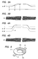
- FIG. 3A an axis of abscissa represents a rotation position of the scale 11, and an axis of ordinate represents a sum, (A 2 + B 2 ), of squares which is obtained by summing up squares of the amplitudes of the two phases encoder signals A and B.
- FIG. 3B is an output waveform chart of the two phases encoder signals A and B.
- the signal A is represented by a solid line
- the signal B is represented by a dashed line.
- FIG. 3A an axis of abscissa represents a rotation position of the scale 11
- an axis of ordinate represents a sum, (A 2 + B 2 ), of squares which is obtained by summing up squares of the amplitudes of the two phases encoder signals A and B.
- FIG. 3B is an output waveform chart of the two phases encoder signals A and B.
- the signal A is represented by a solid line
- the signal B is represented by a dashed line.
- a region in which the amplitudes of the two phases encoder signals A and B are small corresponds to the outputs when the reflecting portion 14a lies in the rear side of the scale 11 in terms of the rotation position, while a region in which the amplitudes of the two phases encoder signals A and B are large corresponds to the outputs when the nonreflecting portion 14b lies in the rear side of the scale 11 in terms of the rotation position.
- a sum of squares is obtained by arithmetically operating the two phases encoder signals A and B taken in by an A/D converter or the like in an arithmetically operation processing circuit such as a microcomputer.
- a boundary line between the reflecting portion 14a and the nonreflecting portion 14b is easy to detect due to a use of a comparison voltage threshold value L.
- the boundary line between the reflecting portion 14a and the nonreflecting portion 14b can be much more clearly detected than that in a case where the two phases encoder signals A and B are simply used.
- the reflecting portion 14a and the nonreflecting portion 14b are detected using the sum of squares, and the counting from the origin is carried out, a zone of the scale 11 can be grasped and moreover the absolute position can be precisely detected based on the two phases encoder signals A and B.
- the scale 11 for stopping the scale 11 in a stop target position, it is understood that when the stop target position of the scale 11 is assigned R determined based on the comparison voltage threshold value L, if for example, the scale 11 is relatively located in a position S in FIG. 3A, a value of the sum of squares obtained from the processing circuit is smaller than the comparison voltage threshold value L which is set in advance. Thus, the scale 11 can be driven to relatively move to a right-hand side in paper by driving means such as an actuator to reach the stop target position R. Conversely, when the scale 11 is located in a position T, a value of the sum of squares is larger than the comparison voltage threshold value L. Thus, the scale 11 has to be driven to relatively move to a left-hand side in the paper to reach the stop target position R.
- the scale can be readily made reach the stop target position through the shortest distance.
- Embodiment 1 adopts the construction in which the positions of two regions for allowing the signal levels to change in positions permitting 180° in position shift can be detected using the reflecting portion 14a and the nonreflecting portion 14b.
- a plurality of portions different in reflectivity from one another may be stepwisely provided to further divide a zone in order to carry out the detection.
- the light receiving portion 13 is constituted by a photodiode array and thus a plurality of light and darkness of the reflected light are detected, one or more patterns of the scale 11 are lacked, thereby allowing the signal levels to be changed.
- FIG. 4A shows an example in which, in Embodiment 1, the characteristics of circuit components are changed due to a temperature change or a long term change, and thus detection becomes unable to be carried out.
- the amplitude value of the sum, (A 2 + B 2 ), of squares follows a dashed line P.
- the comparison voltage threshold value L which is set in advance
- FIG. 5 is a perspective view showing a construction of an encoder according to Embodiment 2 of the present invention for solving the above problem.
- a reflecting portion 22a and a nonreflecting portion 22b each having a half-moon shape are provided in a rear surface of a disc-like scale 21.
- the reflecting portion 22a lies in the rear surface of the disc-like scale 21.
- the excessive light returns back to the light receiving portion.
- the contrast in the sensor is reduced so that the two phases encoder signals A and B each having a sufficient amplitude cannot be obtained.
- two sets of sensor heads 23 and 24 each having a light emitting portion and a light receiving portion are disposed in places which are shifted in position by right 180° across the scale 21 from each other.
- a solid line P1 represents a level of a sum of squares of the two phases encoder signals A and B from the sensor head 23 shown in FIG. 5
- a dashed line P2 represents a level of a sum of squares of the two phases encoder signals A and B from the sensor head 24 shown in FIG. 5.
- the signal outputs P1 and P2 show the sums of squares the levels of which are opposite in vertical timing to each other.
- the signal amplitude based on the sum of squares of the two phases encoder signals A and B from the sensor head 23 takes a small value P1' since the reflecting portion 22a lies in the rear surface of the scale 21, and conversely, the signal amplitude based on the sum of squares of the two phases encoder signals A and B from the sensor head 24 takes a large value P2' since the nonreflecting portion 22b lies in the rear surface of the scale 21.
- a solid line P3 represents an arithmetic operation output corresponding to a difference between the sum, P1, of squares from the sensor head 23 and the sum, P2, of squares from the sensor head 24.
- the arithmetic operation output P3 becomes plus in sign when the sum, P1, of squares is larger than the sum, P2, of squares, and becomes minus in sign when the sum, P1, of squares is smaller than the sum, P2, of squares.
- the zone information related to where the scale 21 is located can be obtained based on the sum, P1, of squares from the sensor head 23 and the sum, P2, of squares from the sensor head 24 when the encoder is stopped.
- Embodiment 2 in order to detect the absolute position, the two sensor heads 23 and 24 are disposed.
- this construction when an average of the positional information obtained through the arithmetic operation for Arctan or the like is obtained from the values obtained in the sensor heads 23 and 24, respectively, even if the scale 21 is mounted in a state of being biased, this influence can be canceled and hence a precise positional signal is obtained.
- a region in which amplitudes of the two phases signals (A, B) are small corresponds to outputs when a reflecting portion lies in the scale in terms of rotation position
- a region in which amplitudes of the two phases signals (A, B) are large corresponds to outputs when a nonreflecting portion lies in the scale in terms of rotation position.
- An optical encoder for discriminating positions of a reflecting portion and a nonreflecting portion of a scale using a threshold value (L) to detect an absolute position based on a reason that when the signals (A, B) are arithmetically operated by an arithmetic operation processing circuit to obtain a sum of squares of the signals (A, B), change points in the amplitudes of the signals (A, B) are steeply obtained.
Landscapes
- Physics & Mathematics (AREA)
- General Physics & Mathematics (AREA)
- Optical Transform (AREA)
Applications Claiming Priority (2)
| Application Number | Priority Date | Filing Date | Title |
|---|---|---|---|
| JP2004155772 | 2004-05-26 | ||
| JP2004155772A JP2005337843A (ja) | 2004-05-26 | 2004-05-26 | 光学式エンコーダ |
Publications (2)
| Publication Number | Publication Date |
|---|---|
| EP1600740A2 true EP1600740A2 (fr) | 2005-11-30 |
| EP1600740A3 EP1600740A3 (fr) | 2006-10-04 |
Family
ID=34936151
Family Applications (1)
| Application Number | Title | Priority Date | Filing Date |
|---|---|---|---|
| EP05009797A Withdrawn EP1600740A3 (fr) | 2004-05-26 | 2005-05-04 | Codeur optique |
Country Status (5)
| Country | Link |
|---|---|
| US (1) | US7391011B2 (fr) |
| EP (1) | EP1600740A3 (fr) |
| JP (1) | JP2005337843A (fr) |
| KR (1) | KR100820268B1 (fr) |
| CN (1) | CN1702433B (fr) |
Cited By (1)
| Publication number | Priority date | Publication date | Assignee | Title |
|---|---|---|---|---|
| EP1882908A3 (fr) * | 2006-07-19 | 2013-08-28 | Canon Kabushiki Kaisha | Capteur réflectif |
Families Citing this family (16)
| Publication number | Priority date | Publication date | Assignee | Title |
|---|---|---|---|---|
| KR101442290B1 (ko) * | 2007-01-11 | 2014-09-19 | 쓰리엠 이노베이티브 프로퍼티즈 컴파니 | 웨브 종방향 위치 센서 |
| DE102007020761B3 (de) * | 2007-05-03 | 2008-11-20 | Siemens Ag | Messanordnung mit einer überwachten Messeinheit und einer Steuereinheit zur Steuerung einer Maschine |
| EP2165162A2 (fr) * | 2007-06-19 | 2010-03-24 | 3M Innovative Properties Company | Échelle de déplacement de réflexion interne totale |
| KR101647265B1 (ko) * | 2007-06-19 | 2016-08-09 | 쓰리엠 이노베이티브 프로퍼티즈 컴파니 | 변위 스케일을 제조하는 시스템 및 방법 |
| KR101493115B1 (ko) * | 2007-06-19 | 2015-02-12 | 쓰리엠 이노베이티브 프로퍼티즈 컴파니 | 웨브의 위치를 나타내는 시스템 및 방법 |
| US20100188951A1 (en) * | 2007-08-08 | 2010-07-29 | Eliezer Zeichner | Encoding device, system and method |
| KR101667071B1 (ko) | 2008-12-29 | 2016-10-17 | 쓰리엠 이노베이티브 프로퍼티즈 컴파니 | 웨브 기점을 사용한 위상-고정된 웨브 위치 신호 |
| US8992104B2 (en) | 2008-12-30 | 2015-03-31 | 3M Innovative Properties Company | Apparatus and method for making fiducials on a substrate |
| JP5641746B2 (ja) * | 2010-02-12 | 2014-12-17 | 株式会社ミツトヨ | 光電式エンコーダ |
| JP5408342B2 (ja) | 2010-04-02 | 2014-02-05 | 株式会社安川電機 | エンコーダ、駆動装置、絶対位置算出方法及びエンコーダ製造方法 |
| JP5993564B2 (ja) * | 2011-07-13 | 2016-09-14 | 新日本無線株式会社 | 反射型フォトセンサを用いた位置検出装置 |
| JP6168762B2 (ja) * | 2012-12-14 | 2017-07-26 | キヤノン株式会社 | アブソリュートエンコーダ |
| JP6474289B2 (ja) * | 2015-03-19 | 2019-02-27 | 株式会社キーエンス | 光学式ロータリーエンコーダ |
| US10634523B2 (en) * | 2016-05-03 | 2020-04-28 | Arges Gmbh | Optical rotation angle measuring system |
| JP2019158850A (ja) * | 2018-03-16 | 2019-09-19 | 富士電機株式会社 | 反射型エンコーダ |
| JP7667025B2 (ja) * | 2021-08-06 | 2025-04-22 | 株式会社荏原製作所 | 研磨装置および研磨装置における研磨終点検出方法 |
Family Cites Families (9)
| Publication number | Priority date | Publication date | Assignee | Title |
|---|---|---|---|---|
| US4445110A (en) * | 1980-07-28 | 1984-04-24 | Itek Corporation | Absolute optical encoder system |
| US4360730A (en) * | 1980-10-16 | 1982-11-23 | Itek Corporation | Encoder alignment method and apparatus |
| JPS60113107A (ja) * | 1983-11-25 | 1985-06-19 | Sankyo Seiki Mfg Co Ltd | 光学式エンコ−ダ− |
| JPH0656304A (ja) | 1992-07-03 | 1994-03-01 | Nec Eng Ltd | 記録紙残量表示機構 |
| US6630659B1 (en) * | 1994-06-01 | 2003-10-07 | Stridsberg Innovation Ab | Position transducer |
| JP2695623B2 (ja) * | 1994-11-25 | 1998-01-14 | 株式会社ミツトヨ | 光学式エンコーダ |
| US5929789A (en) | 1997-04-09 | 1999-07-27 | Hewlett-Packrd Company | Single channel incremental position encorder with incorporated reference mark |
| JP2003161645A (ja) | 2001-11-28 | 2003-06-06 | Canon Inc | 光学式エンコーダ |
| US6822220B2 (en) * | 2002-06-20 | 2004-11-23 | Hewlett-Packard Development Company, L.P. | Optical pattern for an optical encoder |
-
2004
- 2004-05-26 JP JP2004155772A patent/JP2005337843A/ja active Pending
-
2005
- 2005-05-04 EP EP05009797A patent/EP1600740A3/fr not_active Withdrawn
- 2005-05-25 US US11/137,989 patent/US7391011B2/en not_active Expired - Fee Related
- 2005-05-25 CN CN200510072985.XA patent/CN1702433B/zh not_active Expired - Fee Related
- 2005-05-26 KR KR1020050044482A patent/KR100820268B1/ko not_active Expired - Fee Related
Cited By (1)
| Publication number | Priority date | Publication date | Assignee | Title |
|---|---|---|---|---|
| EP1882908A3 (fr) * | 2006-07-19 | 2013-08-28 | Canon Kabushiki Kaisha | Capteur réflectif |
Also Published As
| Publication number | Publication date |
|---|---|
| JP2005337843A (ja) | 2005-12-08 |
| CN1702433B (zh) | 2012-06-20 |
| US7391011B2 (en) | 2008-06-24 |
| CN1702433A (zh) | 2005-11-30 |
| KR20060048117A (ko) | 2006-05-18 |
| US20050263689A1 (en) | 2005-12-01 |
| KR100820268B1 (ko) | 2008-04-07 |
| EP1600740A3 (fr) | 2006-10-04 |
Similar Documents
| Publication | Publication Date | Title |
|---|---|---|
| US7391011B2 (en) | Optical encoder capable of detecting absolute position | |
| JP4324261B2 (ja) | 光学位置測定装置用の走査ユニット | |
| KR100738495B1 (ko) | 광학식 엔코더 | |
| JP5147367B2 (ja) | エンコーダ | |
| US6246050B1 (en) | Optical encoders using non-patterned targets | |
| AU2010211097B2 (en) | Optoelectronic position measurement device and optoelectronic position measurement method | |
| US6175414B1 (en) | Optical position measuring device | |
| US7348544B2 (en) | Optical encoder with discontinuous optical grating | |
| US20080067333A1 (en) | Position-measuring device | |
| US20040245442A1 (en) | Position measuring device | |
| US6472658B2 (en) | Photoelectric position measuring system that optimizes modulation of a scanning device and the intensity of a reference mark signal | |
| EP2244071A2 (fr) | Codeur photoélectrique et son procédé de commande | |
| US11946780B2 (en) | Optical encoder and control apparatus | |
| JP2000321097A (ja) | 光学式エンコーダ | |
| US6460765B1 (en) | Label sensor for sensing edges of light conductive labels | |
| GB2430250A (en) | Optical encoder and method therefor | |
| CN113028998B (zh) | 光学位置测量装置 | |
| JPH03189563A (ja) | 光学式速度センサー及び光学式位置センサー | |
| EP1577646B1 (fr) | Codeur optique | |
| JP2005265512A (ja) | 光学式エンコーダ | |
| JPH0399220A (ja) | エンコーダ | |
| JPH03287015A (ja) | 反射型光学式変位検出器 | |
| JP2002236034A (ja) | 光学式エンコーダ | |
| JPS6350720A (ja) | 位置センサ | |
| GB2457834A (en) | Optical encoder using reflectors on a code member to reflect light and to produce light spots that travel across a detector array |
Legal Events
| Date | Code | Title | Description |
|---|---|---|---|
| PUAI | Public reference made under article 153(3) epc to a published international application that has entered the european phase |
Free format text: ORIGINAL CODE: 0009012 |
|
| AK | Designated contracting states |
Kind code of ref document: A2 Designated state(s): AT BE BG CH CY CZ DE DK EE ES FI FR GB GR HU IE IS IT LI LT LU MC NL PL PT RO SE SI SK TR |
|
| AX | Request for extension of the european patent |
Extension state: AL BA HR LV MK YU |
|
| PUAL | Search report despatched |
Free format text: ORIGINAL CODE: 0009013 |
|
| AK | Designated contracting states |
Kind code of ref document: A3 Designated state(s): AT BE BG CH CY CZ DE DK EE ES FI FR GB GR HU IE IS IT LI LT LU MC NL PL PT RO SE SI SK TR |
|
| AX | Request for extension of the european patent |
Extension state: AL BA HR LV MK YU |
|
| 17P | Request for examination filed |
Effective date: 20070404 |
|
| AKX | Designation fees paid |
Designated state(s): DE FR GB NL |
|
| 17Q | First examination report despatched |
Effective date: 20121214 |
|
| STAA | Information on the status of an ep patent application or granted ep patent |
Free format text: STATUS: THE APPLICATION HAS BEEN WITHDRAWN |
|
| 18W | Application withdrawn |
Effective date: 20130618 |