EP1602014B1 - Verfahren und vorrichtung zum steuern eines torantriebes - Google Patents
Verfahren und vorrichtung zum steuern eines torantriebes Download PDFInfo
- Publication number
- EP1602014B1 EP1602014B1 EP04713046A EP04713046A EP1602014B1 EP 1602014 B1 EP1602014 B1 EP 1602014B1 EP 04713046 A EP04713046 A EP 04713046A EP 04713046 A EP04713046 A EP 04713046A EP 1602014 B1 EP1602014 B1 EP 1602014B1
- Authority
- EP
- European Patent Office
- Prior art keywords
- door drive
- speed
- torques
- torque
- maximum
- Prior art date
- Legal status (The legal status is an assumption and is not a legal conclusion. Google has not performed a legal analysis and makes no representation as to the accuracy of the status listed.)
- Expired - Lifetime
Links
Images


Classifications
-
- G—PHYSICS
- G05—CONTROLLING; REGULATING
- G05B—CONTROL OR REGULATING SYSTEMS IN GENERAL; FUNCTIONAL ELEMENTS OF SUCH SYSTEMS; MONITORING OR TESTING ARRANGEMENTS FOR SUCH SYSTEMS OR ELEMENTS
- G05B19/00—Program-control systems
- G05B19/02—Program-control systems electric
- G05B19/18—Numerical control [NC], i.e. automatically operating machines, in particular machine tools, e.g. in a manufacturing environment, so as to execute positioning, movement or co-ordinated operations by means of program data in numerical form
- G05B19/19—Numerical control [NC], i.e. automatically operating machines, in particular machine tools, e.g. in a manufacturing environment, so as to execute positioning, movement or co-ordinated operations by means of program data in numerical form characterised by positioning or contouring control systems, e.g. to control position from one programmed point to another or to control movement along a programmed continuous path
- G05B19/21—Numerical control [NC], i.e. automatically operating machines, in particular machine tools, e.g. in a manufacturing environment, so as to execute positioning, movement or co-ordinated operations by means of program data in numerical form characterised by positioning or contouring control systems, e.g. to control position from one programmed point to another or to control movement along a programmed continuous path using an incremental digital measuring device
- G05B19/23—Numerical control [NC], i.e. automatically operating machines, in particular machine tools, e.g. in a manufacturing environment, so as to execute positioning, movement or co-ordinated operations by means of program data in numerical form characterised by positioning or contouring control systems, e.g. to control position from one programmed point to another or to control movement along a programmed continuous path using an incremental digital measuring device for point-to-point control
- G05B19/231—Numerical control [NC], i.e. automatically operating machines, in particular machine tools, e.g. in a manufacturing environment, so as to execute positioning, movement or co-ordinated operations by means of program data in numerical form characterised by positioning or contouring control systems, e.g. to control position from one programmed point to another or to control movement along a programmed continuous path using an incremental digital measuring device for point-to-point control the positional error is used to control continuously the servomotor according to its magnitude
- G05B19/237—Numerical control [NC], i.e. automatically operating machines, in particular machine tools, e.g. in a manufacturing environment, so as to execute positioning, movement or co-ordinated operations by means of program data in numerical form characterised by positioning or contouring control systems, e.g. to control position from one programmed point to another or to control movement along a programmed continuous path using an incremental digital measuring device for point-to-point control the positional error is used to control continuously the servomotor according to its magnitude with a combination of feedback covered by G05B19/232 - G05B19/235
-
- E—FIXED CONSTRUCTIONS
- E05—LOCKS; KEYS; WINDOW OR DOOR FITTINGS; SAFES
- E05F—DEVICES FOR MOVING WINGS INTO OPEN OR CLOSED POSITION; CHECKS FOR WINGS; WING FITTINGS NOT OTHERWISE PROVIDED FOR, CONCERNED WITH THE FUNCTIONING OF THE WING
- E05F15/00—Power-operated mechanisms for wings
- E05F15/40—Safety devices, e.g. detection of obstructions or end positions
- E05F15/41—Detection by monitoring transmitted force or torque; Safety couplings with activation dependent upon torque or force, e.g. slip couplings
-
- E—FIXED CONSTRUCTIONS
- E05—LOCKS; KEYS; WINDOW OR DOOR FITTINGS; SAFES
- E05Y—INDEXING SCHEME ASSOCIATED WITH SUBCLASSES E05D AND E05F, RELATING TO CONSTRUCTION ELEMENTS, ELECTRIC CONTROL, POWER SUPPLY, POWER SIGNAL OR TRANSMISSION, USER INTERFACES, MOUNTING OR COUPLING, DETAILS, ACCESSORIES, AUXILIARY OPERATIONS NOT OTHERWISE PROVIDED FOR, APPLICATION THEREOF
- E05Y2400/00—Electronic control; Electrical power; Power supply; Power or signal transmission; User interfaces
- E05Y2400/10—Electronic control
- E05Y2400/30—Electronic control of motors
- E05Y2400/31—Force or torque control
- E05Y2400/315—Curve setting or adjusting
-
- E—FIXED CONSTRUCTIONS
- E05—LOCKS; KEYS; WINDOW OR DOOR FITTINGS; SAFES
- E05Y—INDEXING SCHEME ASSOCIATED WITH SUBCLASSES E05D AND E05F, RELATING TO CONSTRUCTION ELEMENTS, ELECTRIC CONTROL, POWER SUPPLY, POWER SIGNAL OR TRANSMISSION, USER INTERFACES, MOUNTING OR COUPLING, DETAILS, ACCESSORIES, AUXILIARY OPERATIONS NOT OTHERWISE PROVIDED FOR, APPLICATION THEREOF
- E05Y2400/00—Electronic control; Electrical power; Power supply; Power or signal transmission; User interfaces
- E05Y2400/10—Electronic control
- E05Y2400/45—Control modes
- E05Y2400/456—Control modes for programming, e.g. learning or AI [artificial intelligence]
-
- E—FIXED CONSTRUCTIONS
- E05—LOCKS; KEYS; WINDOW OR DOOR FITTINGS; SAFES
- E05Y—INDEXING SCHEME ASSOCIATED WITH SUBCLASSES E05D AND E05F, RELATING TO CONSTRUCTION ELEMENTS, ELECTRIC CONTROL, POWER SUPPLY, POWER SIGNAL OR TRANSMISSION, USER INTERFACES, MOUNTING OR COUPLING, DETAILS, ACCESSORIES, AUXILIARY OPERATIONS NOT OTHERWISE PROVIDED FOR, APPLICATION THEREOF
- E05Y2400/00—Electronic control; Electrical power; Power supply; Power or signal transmission; User interfaces
- E05Y2400/10—Electronic control
- E05Y2400/52—Safety arrangements associated with the wing motor
- E05Y2400/53—Wing impact prevention or reduction
- E05Y2400/54—Obstruction or resistance detection
- E05Y2400/55—Obstruction or resistance detection by using load sensors
- E05Y2400/554—Obstruction or resistance detection by using load sensors sensing motor load
-
- E—FIXED CONSTRUCTIONS
- E05—LOCKS; KEYS; WINDOW OR DOOR FITTINGS; SAFES
- E05Y—INDEXING SCHEME ASSOCIATED WITH SUBCLASSES E05D AND E05F, RELATING TO CONSTRUCTION ELEMENTS, ELECTRIC CONTROL, POWER SUPPLY, POWER SIGNAL OR TRANSMISSION, USER INTERFACES, MOUNTING OR COUPLING, DETAILS, ACCESSORIES, AUXILIARY OPERATIONS NOT OTHERWISE PROVIDED FOR, APPLICATION THEREOF
- E05Y2400/00—Electronic control; Electrical power; Power supply; Power or signal transmission; User interfaces
- E05Y2400/10—Electronic control
- E05Y2400/52—Safety arrangements associated with the wing motor
- E05Y2400/53—Wing impact prevention or reduction
- E05Y2400/54—Obstruction or resistance detection
- E05Y2400/58—Sensitivity setting or adjustment
-
- E—FIXED CONSTRUCTIONS
- E05—LOCKS; KEYS; WINDOW OR DOOR FITTINGS; SAFES
- E05Y—INDEXING SCHEME ASSOCIATED WITH SUBCLASSES E05D AND E05F, RELATING TO CONSTRUCTION ELEMENTS, ELECTRIC CONTROL, POWER SUPPLY, POWER SIGNAL OR TRANSMISSION, USER INTERFACES, MOUNTING OR COUPLING, DETAILS, ACCESSORIES, AUXILIARY OPERATIONS NOT OTHERWISE PROVIDED FOR, APPLICATION THEREOF
- E05Y2800/00—Details, accessories and auxiliary operations not otherwise provided for
-
- G—PHYSICS
- G05—CONTROLLING; REGULATING
- G05B—CONTROL OR REGULATING SYSTEMS IN GENERAL; FUNCTIONAL ELEMENTS OF SUCH SYSTEMS; MONITORING OR TESTING ARRANGEMENTS FOR SUCH SYSTEMS OR ELEMENTS
- G05B2219/00—Program-control systems
- G05B2219/30—Nc systems
- G05B2219/37—Measurements
- G05B2219/37624—Detect collision, blocking by measuring change of velocity or torque
-
- G—PHYSICS
- G05—CONTROLLING; REGULATING
- G05B—CONTROL OR REGULATING SYSTEMS IN GENERAL; FUNCTIONAL ELEMENTS OF SUCH SYSTEMS; MONITORING OR TESTING ARRANGEMENTS FOR SUCH SYSTEMS OR ELEMENTS
- G05B2219/00—Program-control systems
- G05B2219/30—Nc systems
- G05B2219/37—Measurements
- G05B2219/37632—By measuring current, load of motor
-
- G—PHYSICS
- G05—CONTROLLING; REGULATING
- G05B—CONTROL OR REGULATING SYSTEMS IN GENERAL; FUNCTIONAL ELEMENTS OF SUCH SYSTEMS; MONITORING OR TESTING ARRANGEMENTS FOR SUCH SYSTEMS OR ELEMENTS
- G05B2219/00—Program-control systems
- G05B2219/30—Nc systems
- G05B2219/45—Nc applications
- G05B2219/45242—Door, panel, window operation, opening, closing
Definitions
- the invention relates to a method and a device for controlling a door drive.
- the measuring passage comprises at least one complete opening and closing cycle of the door drive.
- the opening operation and the closing operation of the door drive are each divided into a predetermined number of zones, wherein the duration of each zone can be determined depending on the specific torques.
- a permissible maximum torque is defined within each zone. The maximum torques are determined for the individual zones such that the permissible maximum torque is at least equal to the largest, during the measurement sweep occurring within the respective zone torque.
- the currently registered torques are compared with the respective maximum torques of the respective zones. If the current torque exceeds the maximum torque of the respective zone, an emergency stop of the door drive takes place.
- An advantage of this method is that a safety function for a door drive is provided with relatively little control effort.
- each zone is assigned only one measured value in the form of the permissible maximum torque as a shutdown criterion for the door drive.
- the disadvantage here is an undesirably large response time of the controller.
- a considerable amount of time may elapse when an obstacle enters the gate until the current torque exceeds the permissible maximum torque.
- This creates undesirably high delay times in the triggering of the emergency stop, which can lead to hazards to persons.
- standard regulations must be observed that define limit values for these delay times. Compliance with such standard provisions is problematic in the method according to DE 196 28 238 A1.
- the invention has for its object a method and an apparatus of the type mentioned in such a way that with the least possible effort secure control of a door drive is ensured.
- the determination of the time profile of the torques of the door drive for at least one opening and closing operation initially takes place during a teaching process. Then permissible maximum torques are derived from the determined torques for predetermined zones within an opening and closing operation. During the subsequent operation of the door drive, a comparison of the current torques with the maximum torques and a comparison of the current speeds of the door drive with predetermined target speeds. In this case, the current speed of the door drive is increased when falling below the associated target speed and the door drive is switched off, if the current torque exceeds the associated maximum torque.
- this switch-off control is combined with a control of the speed of the door drive.
- the speed of the door drive is particularly advantageously regulated to a desired speed profile.
- This combination ensures that the control of the door drive ensures not only a safe but also a sufficiently rapid response of the power cut.
- the door drive 1 shows the structure of a device for controlling a door drive 1.
- the door drive 1 consists essentially of an electric motor which drives a gate 2.
- the gate 2 is formed in the present case of a garage door.
- a computer unit 3 For controlling the door drive 1, a computer unit 3 is provided, which is generally formed by a microprocessor system. In the computer unit 3, a memory unit 4 for storing data and parameters is provided. Furthermore, the computer unit 3 has a control unit 5, by means of which the speed of the door drive 1 is controlled. Finally, the Computing unit 3 on a time measuring unit 6, which essentially has a clock oscillator for specifying a timing.
- a measuring unit 7 is connected to the computer unit 3.
- the measuring unit 7 means for determining the torque and means for determining the speed of the door drive 1 are provided.
- the means for determining the torque of the door drive 1 are essentially formed by a measuring circuit by means of which the current supplied to the electric motor is measured, which forms a measure of the torque of the door drive 1.
- the torque determination is generally interpreted as determining the power requirement, the term torque determination is generally used for the determination of a characteristic for this power demand.
- the means for determining the speed of the door drive 1 are essentially formed by a measuring circuit, by means of which the rotational speed of the electric motor is detected.
- both the time profile of the speed and the torque curve of the door drive 1 can be determined by means of the measuring unit 7.
- the gate 2 can be moved between an upper and lower end position, wherein limit switches 8 are provided for controlling the end positions, the signals of which are guided on the door drive 1.
- Figure 2 shows schematically the temporal torque curve of the door drive 1 during an opening operation, ie during the movement of the door 2 from the lower to the upper end position.
- Figure 3 shows the temporal Torque course of the door drive 1 during a closing operation, ie during the movement of the gate 2 from the upper to the lower end position.
- the torque of the door drive 1 is greatly increased in the start-up phase at the beginning of an opening and closing operation.
- the torque drops sharply after the start-up phase and then increases substantially continuously. Since the door drive 1 is switched off in its upper end position by means of the limit switch 8, a peak of the torque curve, as occurs at the start-up phase, is avoided at the end of the opening process.
- the torque drops substantially continuously after the start-up phase. Also in this case, a high torque peak is suppressed by the limit switch 8 when retracting the door drive 1 in the lower end position.
- a teach-in process is performed before commissioning the door drive 1.
- permissible maximum torques are determined from the torque curves of the opening and closing operation, which serve as a criterion for a force shutdown during operation of the door drive 1.
- the power shutdown provides an emergency stop of the door drive 1 in the event that the gate 2 runs against an obstacle.
- the time torque curve is determined both for a complete opening process and for a complete closing operation by means of the measuring unit 7. In principle, a multiple determination of the torque characteristics can be performed.
- the torque profiles are each subdivided into a number of zones of predetermined time duration.
- the number of zones and the time intervals over which the zones extend can be specific to the application respective door drive 1, and adapted to the respective torque curves are selected.
- the start-up phase with the torque peak during the opening and closing operation is omitted in the zoning.
- the remaining torque curves are divided into the zones.
- the respective maximum torque D imax is determined in the computer unit 3. From this maximum value, a threshold value S i is determined for the respective zone i, which forms the permissible maximum torque within this zone.
- the threshold values S i for the zones i are defined such that in each case the same positive constant ⁇ is added to the maximum torques D imax of the individual zones.
- variable quantities ⁇ i could also be defined for the individual zones, which are added to the respective maximum values D imax .
- a threshold value S 1 as a permissible maximum torque receive.
- the threshold values S 1 , S 2 and S 3 are obtained as permissible maximum torques.
- a force shutdown takes place in which the door drive 1 is switched off via a switching command generated by the computer unit 3.
- a switching output may be integrated, which forms a switching means, via which the switching command can be output.
- external switching means such as relays or the like may be provided.
- the current torque is always below the thresholds S i , since these were derived during the teach-in from the real conditions of the door drive 1 and were also chosen so that the threshold S i of a zone above the occurring in the zone i maximum torque is.
- the door drive 1 additionally detects the current speed of the door drive 1 and compares it with predetermined setpoint values. If the current speed falls below the setpoint, it will be increased again.
- the speed of the door drive 1 is controlled.
- the setpoint values specified for both the opening and closing operation are setpoint speed profiles.
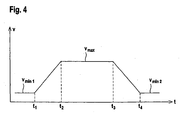
- Figure 4 shows the time course of such a target speed profile for the opening operation of the door drive 1.
- a delay phase in the time interval between t 3 and t 4 , within which the door drive 1 is braked with constant speed gradients from the speed v max to the speed v min2 .
- the door drive 1 is turned off in its upper end position by means of the limit switch 8.
- the velocities v min1 and v min2 are chosen to be the same.
- the desired speed profile for the closing operation corresponds to the shape of the speed profile according to FIG. 4. Only the absolute values for the desired speed values and the lengths of the phases defining times t 1 -t 4 can vary in absolute terms.
- the door drive 1 is accelerated within the predetermined acceleration phase , as shown for example in FIG. 4, from the speed V min1 to the speed V max . Subsequently, the door drive 1 is moved at a constant speed to its end position, the duration of the door drive 1 is detected here. In the computer unit 3, the time t 3 then calculated from this term, at which the deceleration phase is initiated. In this way, the desired speed profile is set both for the opening operation and for the closing operation.
- the speed of the door drive 1 is then regulated by means of the control unit 5 to the predetermined desired speed profile.
Landscapes
- Engineering & Computer Science (AREA)
- Human Computer Interaction (AREA)
- Manufacturing & Machinery (AREA)
- Physics & Mathematics (AREA)
- General Physics & Mathematics (AREA)
- Automation & Control Theory (AREA)
- Power-Operated Mechanisms For Wings (AREA)
- Elevator Door Apparatuses (AREA)
- Control Of Electric Motors In General (AREA)
Description
- Die Erfindung betrifft ein Verfahren und eine Vorrichtung zum Steuern eines Torantriebs.
- Ein derartiges Verfahren ist aus der DE 196 28 238 A1 bekannt. Mit diesem Verfahren wird als Sicherheitsfunktion für einen Torantrieb eine sogenannte Kraftabschaltung bereitgestellt. Dies bedeutet, dass der Torantrieb bei Auftreten eines erhöhten Kraftbedarfs, der insbesondere dadurch entsteht, wenn ein Objekt oder eine Person das mit dem Torantrieb angetriebene Tor blockiert, gestoppt wird, um Verletzungen von Personen oder Beschädigungen von Objekten zu vermeiden.
- Gemäß diesem Verfahren erfolgt vor der Inbetriebnahme des Torantriebs ein Messdurchlauf, bei welchem der tatsächliche Kraftbedarf des Torantriebs über den Verfahrweg ermittelt wird. Dabei umfasst der Messdurchlauf wenigstens jeweils einen kompletten Öffnungs- und Schließzyklus des Torantriebs.
- Der Torantrieb weist einen Elektromotor auf, mit welchem das Tor, insbesondere ein Garagentor angetrieben wird. Der Kraftbedarf des Torantriebs wird durch Bestimmung des Drehmoments des Elektromotors ermittelt. Der Messdurchlauf wird mit konstanter, maximaler Geschwindigkeit, ohne Geschwindigkeitsreduzierung am Ende des Bewegungsweges des Tores durchgeführt.
- Der Öffnungsvorgang und der Schließvorgang des Torantriebs werden jeweils in eine vorgegebene Anzahl von Zonen unterteilt, wobei die Dauer jeder Zone in Abhängigkeit der bestimmten Drehmomente festgelegt werden kann. Innerhalb jeder Zone wird ein zulässiges Maximal-Drehmoment definiert. Die Maximal-Drehmomente werden für die einzelnen Zonen derart bestimmt, dass das zulässige Maximal-Drehmoment wenigstens gleich groß ist wie das größte, während des Messdurchlaufs innerhalb der jeweiligen Zone aufgetretene Drehmoment.
- Während des anschließenden Betriebs des Torantriebs werden die aktuell registrierten Drehmomente mit den jeweiligen Maximal-Drehmomenten der jeweiligen Zonen verglichen. Überschreitet das aktuelle Drehmoment das Maximal-Drehmoment der jeweiligen Zone, erfolgt ein Notstopp des Torantriebs.
- Vorteilhaft bei diesem Verfahren ist, dass mit relativ geringem Steuerungsaufwand eine Sicherheitsfunktion für einen Torantrieb bereitgestellt wird.
- Insbesondere ist vorteilhaft, dass durch die Einteilung der Öffnungs- und Schließvorgänge des Torantriebs in einzelne Zonen nur ein geringer Steuerungsaufwand zur Bereitstellung der Sicherheitsfunktion erforderlich ist.
- Durch die Zoneneinteilung der Öffnungs- und Schließvorgänge erfolgt eine grobe Rastereinteilung dieser Bewegungsabläufe. Dabei wird jeder Zone nur ein Messwert in Form des zulässigen Maximal-Drehmoments als Abschaltkriterium für den Torantrieb zugeordnet.
- Zur Steuerung des Torantriebs werden daher nur wenige Messpunkte benötigt, wodurch die Steuerung mit geringem Aufwand und entsprechend schnell durchgeführt werden kann.
- Nachteilig hierbei ist jedoch eine unerwünscht große Ansprechzeit der Steuerung. Je nach Lage eines aktuell ermittelten Drehmoments innerhalb einer Zone und relativ zu dem zulässigen Maximal-Drehmoment kann bei Eingriff eines Hindernisses in das Tor eine erhebliche Zeitdauer verstreichen, bis das aktuelle Drehmoment das zulässige Maximal-Drehmoment überschreitet. Dadurch entstehen unerwünscht hohe Verzögerungszeiten bei der Auslösung des Not-Stopps, die zu Gefährdungen von Personen führen können. Weiterhin sind bei der Installation von Torantrieben Normvorschriften zu beachten, die Grenzwerte für diese Verzögerungszeiten definieren. Die Einhaltung derartiger Normvorschriften ist bei dem Verfahren gemäß der DE 196 28 238 A1 problematisch.
- Der Erfindung liegt die Aufgabe zugrunde ein Verfahren und eine Vorrichtung der eingangs genannten Art so auszubilden, dass mit möglichst geringem Aufwand eine sichere Steuerung eines Torantriebs gewährleistet ist.
- Zur Lösung dieser Aufgabe sind die Merkmale der Ansprüche 1 und 12 vorgesehen. Vorteilhafte Ausführungsformen und zweckmäßige Weiterbildungen der Erfindung sind in den Unteransprüchen beschrieben.
- Bei dem erfindungsgemäßen Verfahren zum Steuern eines elektrischen Torantriebs erfolgt zunächst während eines Einlernvorgangs die Bestimmung des zeitlichen Verlaufs der Drehmomente des Torantriebs für jeweils wenigstens einen Öffnungs- und Schließvorgang. Dann werden zulässige Maximal- Drehmomente aus den ermittelten Drehmomenten für vorgegebene Zonen innerhalb eines Öffnungs- und Schließvorganges abgeleitet. Während des anschließendenden Betriebs des Torantriebs erfolgt ein Vergleich der aktuellen Drehmomente mit den Maximal-Drehmomenten und ein Vergleich der aktuellen Geschwindigkeiten des Torantriebs mit vorgegebenen Soll-Geschwindigkeiten. Dabei wird die aktuelle Geschwindigkeit des Torantriebes bei Unterschreiten der zugeordneten Soll-Geschwindigkeit erhöht und der Torantrieb abgeschaltet, falls das aktuelle Drehmoment das zugeordnete Maximal-Drehmoment übersteigt.
- Bei dem erfindungsgemäßen Verfahren werden somit als Abschaltkriterium für den Torantrieb innerhalb der einzelnen Zonen des Öffnungs- und Schließvorgangs Maximal-Drehmomente definiert, wobei ein Not-Stopp des Torantriebs dann erfolgt, wenn das aktuelle Drehmoment des Torantriebs das jeweilige Maximal-Drehmoment überschreitet.
- Erfindungsgemäß wird diese Abschaltkontrolle mit einer Kontrolle der Geschwindigkeit des Torantriebs kombiniert. Besonders vorteilhaft wird dabei die Geschwindigkeit des Torantriebs auf ein Soll-Geschwindigkeitsprofil geregelt.
- Durch diese Kombination wird erreicht, dass die Steuerung des Torantriebs nicht nur ein sicheres sondern auch ein hinreichend schnelles Ansprechen der Kraftabschaltung gewährleistet.
- Liegt ein Eingriff eines Hindernisses in dem zu steuernden Tor vor, so wird nicht nur der Kraftbedarf des Torantriebs erhöht, der einer Drehmomenterhöhung entspricht. Vielmehr sinkt dabei gleichzeitig auch die Drehzahl des Torantriebs, was einer Reduzierung der Geschwindigkeit entspricht, so dass die aktuelle Geschwindigkeit unter die jeweils vorgegebene Soll-Geschwindigkeit absinkt.
- Erfindungsgemäß wird hierauf die aktuelle Geschwindigkeit erhöht, wobei diese vorzugsweise auf die Soll-Geschwindigkeit geregelt wird. Dadurch wird nicht nur die Drehzahl des Torantriebs erhöht, sondern über die Spannung des Torantriebs auch die Stromstärke und damit das Drehmoment des Torantriebs.
- Dadurch wird bei einem bleibenden Hinderniseingriff erreicht, dass das aktuelle Drehmoment rasch erhöht wird und dementsprechend schnell das zulässige Maximal-Drehmoment überschreitet. Damit wird eine äußerst kurze Ansprechzeit der Kraftabschaltung erhalten, wodurch einerseits Gefährdungen für Personen und Objekte sicher vermieden werden und zudem die geltenden Normvorschriften für die Kraftabschaltung eingehalten werden können.
- Bei einer kurzfristigen Drehmomenterhöhung, die zum Beispiel durch zusätzliche Reibung in der Führung des Tores bei Verschmutzungen oder dergleichen entstehen kann, wird durch eine kurzfristige Geschwindigkeitserhöhung das Hindernis überwunden, ohne dass die Kraftabschaltung aktiviert wird. Dadurch wird die Verfügbarkeit des Torantriebs erhöht.
- Die Erfindung wird im Nachstehenden anhand der Zeichnungen erläutert. Es zeigen:
- Figur 1:
- Schematische Darstellung einer Vorrichtung zur Steuerung eines Torantriebs.
- Figur 2:
- Schematische Darstellung des zeitlichen Drehmomentenverlaufs des Torantriebs gemäß Figur 1 für einen Öffnungsvorgang.
- Figur 3:
- Schematische Darstellung des zeitlichen Drehmomentenverlaufs des Torantriebs gemäß Figur 1 für einen Schließvorgang.
- Figur 4:
- Schematische Darstellung des Geschwindigkeitsprofils des Torantriebs gemäß Figur 1 für einen Öffnungsvorgang.
- Figur 1 zeigt den Aufbau einer Vorrichtung zum Steuern eines Torantriebs 1. Der Torantrieb 1 besteht im Wesentlichen aus einem Elektromotor, der ein Tor 2 antreibt. Das Tor 2 ist im vorliegenden Fall von einem Garagentor gebildet.
- Zur Steuerung des Torantriebs 1 ist eine Rechnereinheit 3 vorgesehen, die allgemein von einem Mikroprozessorsystem gebildet ist. In der Rechnereinheit 3 ist eine Speichereinheit 4 zur Speicherung von Daten und Parametern vorgesehen. Weiterhin weist die Rechnereinheit 3 eine Reglereinheit 5 auf, mittels der die Geschwindigkeit des Torantriebs 1 geregelt wird. Schließlich weist die Rechnereinheit 3 eine Zeitmesseinheit 6 auf, welche im Wesentlichen einen Taktoszillator zur Vorgabe eines Zeittaktes aufweist.
- An die Rechnereinheit 3 ist eine Messeinheit 7 angeschlossen. In der Messeinheit 7 sind Mittel zur Bestimmung des Drehmoments sowie Mittel zur Bestimmung der Geschwindigkeit des Torantriebs 1 vorgesehen.
- Die Mittel zur Bestimmung des Drehmoments des Torantriebs 1 sind im Wesentlichen von einer Messschaltung gebildet, mittels derer die dem Elektromotor zugeführte Stromstärke gemessen wird, welche ein Maß für das Drehmoment des Torantriebs 1 bildet. Die Drehmomentbestimmung ist allgemein als Bestimmung des Kraftbedarfs auszulegen, wobei der Begriff Drehmomentbestimmung generell für die Bestimmung einer Kenngröße für diesen Kraftbedarf verwendet wird.
- Die Mittel zur Bestimmung der Geschwindigkeit des Torantriebs 1 sind im Wesentlichen von einer Messschaltung gebildet, mittels derer die Drehzahl des Elektromotors erfasst wird.
- In Kombination der Zeitmesseinheit 6 der Rechnereinheit 3 kann mittels der Messeinheit 7 sowohl der zeitliche Verlauf der Geschwindigkeit als auch der Drehmomentenverlauf des Torantriebs 1 bestimmt werden.
- Das Tor 2 kann zwischen einer oberen und unteren Endlage bewegt werden, wobei zur Kontrolle der Endlagen Endschalter 8 vorgesehen sind, dessen Signale auf dem Torantrieb 1 geführt sind.
- Figur 2 zeigt schematisch den zeitlichen Drehmomentenverlauf des Torantriebs 1 während eines Öffnungsvorgangs, d. h. während der Bewegung des Tores 2 aus der unteren in die obere Endlage. Entsprechend zeigt Figur 3 den zeitlichen Drehmomentenverlauf des Torantriebs 1 während eines Schließvorganges, d. h. während der Bewegung des Tores 2 aus der oberen in die untere Endlage.
- Wie aus den Figuren 2 und 3 ersichtlich, ist das Drehmoment des Torantriebs 1 in der Anlaufphase zu Beginn eines Öffnung- und Schließvorgangs stark erhöht. Bei dem in Figur 2 dargestellten Öffnungsvorgang fällt das Drehmoment nach der Anlaufphase stark ab und steigt dann im Wesentlichen kontinuierlich an. Da der Torantrieb 1 in seiner oberen Endlage mittels des Endschalters 8 abgeschaltet wird, wird am Ende des Öffnungsvorgangs ein Peak des Drehmomentenverlaufs, wie er bei der Anlaufphase auftritt, vermieden. Bei dem in Figur 3 dargestellten Schließvorgang fällt das Drehmoment nach der Anlaufphase im Wesentlichen kontinuierlich ab. Auch in diesem Fall wird bei Einfahren des Torantriebs 1 in die untere Endlage durch den Endschalter 8 ein hoher Drehmoment-Peak unterdrückt.
- Vor Inbetriebnahme des Torantriebs 1 wird ein Einlernvorgang durchgeführt. Innerhalb des Einlernvorgangs werden aus den Drehmomentenverläufen des Öffnungs- und Schließvorgangs zulässige Maximal-Drehmomente bestimmt, welche als Kriterium für eine Kraftabschaltung während des Betriebs des Torantriebs 1 dienen. Die Kraftabschaltung sieht einen Not-Stopp des Torantriebs 1 für den Fall vor, dass das Tor 2 gegen ein Hindernis läuft.
- Während des Einlernvorganges wird mittels der Messeinheit 7 der zeitliche Drehmomentenverlauf sowohl für einen kompletten Öffnungsvorgang als auch für einen kompletten Schließvorgang ermittelt. Prinzipiell kann auch eine Mehrfachbestimmung der Drehmomentenverläufe durchgeführt werden.
- Die Drehmomentenverläufe werden jeweils in eine Anzahl von Zonen vorgegebener Zeitdauer unterteilt. Die Anzahl der Zonen sowie die Zeitintervalle, über welche sich die Zonen erstrecken, können applikationsspezifisch für den jeweiligen Torantrieb 1, und angepasst an die jeweiligen Drehmomentenverläufe gewählt werden.
- Im vorliegenden Fall wird bei der Zoneneinteilung die Anlaufphase mit dem Drehmomentenpeak während des Öffnungs- und Schließvorgangs ausgespart. Die verbleibenden Drehmomentenverläufe werden in die Zonen unterteilt.
- Für den Öffnungsvorgang wird wie in Figur 2 dargestellt nur eine Zone definiert, deren Dauer T = t2- t1 sich über den gesamten an die Anlaufphase anschließenden Drehmomentenverlauf erstreckt.
- Für den Schließvorgang werden im vorliegenden Fall drei Zonen gleicher Dauer definiert. Die Dauer T, der ersten Zone beträgt T1 = t2 - t1. Die Dauer der zweiten Zone beträgt T2 = t3 - t2. Die Dauer der dritten Zone beträgt T3 = t4 - t3.
- Innerhalb jeder Zone i wird in der Rechnereinheit 3 das jeweilige maximale Drehmoment Dimax bestimmt. Aus diesem Maximalwert wird für die jeweilige Zone i ein Schwellwert Si bestimmt, welcher das zulässige Maximal-Drehmoment innerhalb dieser Zone bildet. Im vorliegenden Ausführungsbeispiel werden die Schwellwerte Si für die Zonen i derart definiert, dass zu den maximalen Drehmomenten Dimax der einzelnen Zonen jeweils dieselbe positive Konstante Δ addiert wird. Somit werden die Schwellwerte Si gemäß folgender Beziehung berechnet:

- Prinzipiell könnten für die einzelnen Zonen auch variable Größen Δi definiert werden, die zu den jeweiligen Maximalwerten Dimax addiert werden.
- Im vorliegenden Fall wird als Ergebnis des Einlernvorgangs für die Zone des Öffnungsvorgangs ein Schwellwert S1 als zulässiges Maximal-Drehmoment erhalten. Für die drei Zonen i = 1, 2, 3 des Schließvorganges werden die Schwellwerte S1, S2 und S3 als zulässige Maximal-Drehmomente erhalten.
- Während des auf den Einlernvorgang folgenden Betriebs des Torantriebs 1 werden sowohl für den Öffnungs- als auch für den Schließvorgang fortlaufend die aktuellen Drehmomente bestimmt und mit den zulässigen Maximal-Drehmomenten verglichen. Während des Öffnungsvorgangs wird somit das aktuelle Drehmoment mit dem Schwellwert S1 gemäß Figur 2 verglichen. Während des Schließvorgangs wird abhängig davon, in welcher Zone i das aktuelle Drehmoment liegt, dieses mit dem zu dieser Zone gehörenden Schwellwert S1, S2 oder S3 verglichen.
- Sobald das aktuelle Drehmoment den jeweils aktuellen Schwellwert Si überschreitet erfolgt eine Kraftabschaltung, in dem der Torantrieb 1 über einen von der Rechnereinheit 3 generierten Schaltbefehl abgeschaltet wird. In der Rechnereinheit 3 kann ein Schaltausgang integriert sein, welcher ein Schaltmittel bildet, über welches der Schaltbefehl ausgebbar ist. Prinzipiell können auch externe Schaltmittel wie Relais oder dergleichen vorgesehen sein.
- Auf diese Weise erfolgt ein wirksamer Schutz von Personen oder Objekten, die in den Torantrieb 1 eintreten und diesen blockieren.
- Bei regulärem Betrieb des Torantriebs 1 liegt das aktuelle Drehmoment immer unterhalb der Schwellwerte Si, da diese während des Einlernvorganges aus den Realbedingungen des Torantriebs 1 abgeleitet wurden und zudem so gewählt wurden, dass der Schwellwert Si einer Zone oberhalb des in der Zone i auftretenden maximalen Drehmoments liegt.
- Blockiert ein Hindernis das Tor 2, wird der Kraftbedarf des Torantriebs 1 und damit dessen Drehmoment erhöht, so dass der Wert des Drehmoments oberhalb des jeweiligen Schwellwerts Si liegt, wodurch die Kraftabschaltung ausgelöst wird.
- Je nach Lage des aktuellen Drehmoments innerhalb der jeweiligen Zone verstreicht eine gewisse Zeitspanne, bis die Drehmomenterhöhung infolge eines Hinderniseingriffs zur Auslösung der Kraftabschaltung führt.
- Um diese Verzögerungszeit möglichst kurz zu halten, wird bei dem Torantrieb 1 zusätzlich die aktuelle Geschwindigkeit des Torantriebs 1 erfasst und mit vorgegebenen Sollwerten verglichen. Unterschreitet die aktuelle Geschwindigkeit den Sollwert, so wird diese wieder erhöht.
- Bei einem Hinderniseingriff in das Tor 2 wird neben einer Drehmomentenerhöhung auch eine Drehzahlverminderung und damit eine Geschwindigkeitsreduzierung des Torantriebs 1 erhalten. Durch die darauffolgende Erhöhung der Geschwindigkeit des Torantriebs 1 wird die Stromstärke und damit auch das Drehmoment des Torantriebs 1 erhöht. Durch diesen Effekt wird der Drehmomentanstieg bei einem Hinderniseingriff beschleunigt und damit die Verzögerungszeit zwischen dem Beginn des Hindemisseingriffs und der Kraftabschaltung erheblich vermindert. Bei einer kurzzeitigen Drehmomenterhöhung, die zum Beispiel durch Reibungseffekte verursacht wird, bleibt das aktuelle Drehmoment trotz einer kurzen Geschwindigkeitserhöhung unterhalb des jeweiligen Schwellwerts, sodass eine unnötige Kraftabschaltung vermieden wird.
- In einer besonders vorteilhaften Ausführungsform wird die Geschwindigkeit des Torantriebs 1 geregelt. Als Sollwerte sind sowohl für den Öffnungs- und Schließvorgang Soll-Geschwindigkeitsprofile vorgegeben. Figur 4 zeigt den zeitlichen Verlauf eines solchen Soll-Geschwindigkeitsprofils für den Öffnungsvorgang des Torantriebs 1. Nach dem Ausfahren des Tores 2 aus seiner unteren Endlage wird der Torantrieb 1 während einer Beschleunigungsphase im Zeitintervall zwischen t1 und t2 mit einer konstanten Beschleunigung von einer Geschwindigkeit vmin1 auf eine Geschwindigkeit vmax beschleunigt. Dann schließt eine Phase an, innerhalb derer die Geschwindigkeit des Torantriebs 1 konstant bei vmax gehalten wird. Diese Phase liegt in dem Zeitintervall zwischen t2 und t3. Daran schließt eine Verzögerungsphase im Zeitintervall zwischen t3 und t4 an, innerhalb derer der Torantrieb 1 mit konstanten Geschwindigkeitsgradienten von der Geschwindigkeit vmax auf die Geschwindigkeit vmin2 abgebremst wird. Anschließend wird der Torantrieb 1 in seiner oberen Endlage mittels des Endschalters 8 abgeschaltet. Im vorliegenden Fall sind die Geschwindigkeiten vmin1 und vmin2 gleich groß gewählt. Das Soll-Geschwindigkeitsprofil für den Schließvorgang entspricht der Form des Geschwindigkeitsprofils gemäß Figur 4. Lediglich die Absolutwerte für die Soll-Geschwindigkeitswerte sowie die Längen der Phasen definierenden Zeiten t1 - t4 können betragsmäßig variieren.
- Dabei sind die Geschwindigkeiten vmin1, vmin2 und vmax als Geschwindigkeitsparameter zur Vorgabe der Soll-Geschwindigkeitsprofile in der Speichereinheit 4 der Rechnereinheit 3 hinterlegt. Vorzugsweise sind auch die Geschwindigkeitsgradienten während der Beschleunigungs- und Verzögerungsphase in der Speichereinheit 4 hinterlegt.
- Die genaue Vorgabe der Soll-Geschwindigkeitsprofile erfolgt zweckmäßig während eines Lernlaufs. Bei diesem Lernlauf wird sowohl während des Öffnungsvorgangs als auch während des Schließvorgangs der Torantrieb 1 innerhalb der vorgegebenen Beschleunigungsphase, wie beispielsweise in Figur 4 dargestellt, von der Geschwindigkeit Vmin1 auf die Geschwindigkeit Vmax beschleunigt. Anschließend wird der Torantrieb 1 mit konstanter Geschwindigkeit bis in seine Endlage verfahren, wobei die Laufzeit des Torantriebs 1 hierbei erfasst wird. In der Rechnereinheit 3 wird dann aus dieser Laufzeit der Zeitpunkt t3 berechnet, an welchem die Verzögerungsphase einzuleiten ist. Auf diese Weise ist das Soll-Geschwindigkeitsprofil sowohl für den Öffnungsvorgang als auch für den Schließvorgang festgelegt.
- Während des Betriebs des Torantriebs 1 wird dann die Geschwindigkeit des Torantriebs 1 mittels der Reglereinheit 5 auf das vorgegebene Soll-Geschwindigkeitsprofil geregelt.
-
- (1)
- Torantrieb
- (2)
- Tor
- (3)
- Rechnereinheit
- (4)
- Speichereinheit
- (5)
- Reglereinheit
- (6)
- Zeitmesseinheit
- (7)
- Messeinheit
- (8)
- Endschalter
Claims (17)
- Verfahren zum Steuern eines elektrischen Torantriebs umfassend folgende Verfahrensschritte:- Bestimmung des zeitlichen Verlaufs der Drehmomente des Torantriebs während eines Einlernvorgangs für jeweils wenigstens einen Öffnungs- und Schließvorgang,- Ableiten zulässiger Maximal-Drehmomente aus den ermittelten Drehmomenten für vorgegebene Zonen innerhalb eines Öffnungs- und Schließvorganges,- Vergleich der aktuellen Drehmomente mit den Maximal-Drehmomenten und Vergleich der aktuellen Geschwindigkeiten des Torantriebs mit vorgegebenen Soll-Geschwindigkeiten während des Betriebs des Torantriebs,- Erhöhen der aktuellen Geschwindigkeit des Torantriebes bei Unterschreiten der zugeordneten Soll-Geschwindigkeit,- Abschalten des Torantriebs, falls das aktuelle Drehmoment das zugeordnete Maximal-Drehmoment übersteigt.
- Verfahren nach Anspruch 1, dadurch gekennzeichnet, dass für den Öffnungsvorgang und den Schließvorgang jeweils ein Soll-Geschwindigkeitsprofil vorgegeben ist.
- Verfahren nach Anspruch 2, dadurch gekennzeichnet, dass die aktuelle Geschwindigkeit geregelt wird, wobei die Sollwerte des Regelkreises von den Soll-Geschwindigkeitsprofilen gebildet sind.
- Verfahren nach einem der Ansprüche 2 oder 3, dadurch gekennzeichnet, dass die Soll-Geschwindigkeitsprofile durch Geschwindigkeitsparameter definiert werden.
- Verfahren nach Anspruch 4, dadurch gekennzeichnet, dass jedes Geschwindigkeitsprofil von einer Beschleunigungsphase mit konstanten Geschwindigkeitsgradienten zur Beschleunigung von einer Geschwindigkeit vmin1 auf eine Maximalgeschwindigkeit vmax, von einer darauffolgenden Phase mit konstanter Geschwindigkeit vmax und von einer Verzögerungsphase mit konstantem Geschwindigkeitsgradienten zur Abbremsung von der Maximalgeschwindigkeit vmax auf eine Geschwindigkeit vmin2 gebildet ist.
- Verfahren nach Anspruch 5, dadurch gekennzeichnet, dass die Geschwindigkeiten vmin1, vmin2 und vmax die Geschwindigkeitsgradienten sowie die Dauer jeder Phase die Geschwindigkeitsparameter bilden.
- Verfahren nach einem der Ansprüche 5 oder 6, dadurch gekennzeichnet, dass zur Bestimmung eines Geschwindigkeitsprofils ein Lernlauf durchgeführt wird, bei welchem der Torantrieb (1) während der Beschleunigungsphase von der Geschwindigkeit vmin1 auf die Maximalgeschwindigkeit vmax beschleunigt wird, wobei der Torantrieb (1) mit dieser Maximalgeschwindigkeit vmax in seine Endlage verfahren wird, und dass aus der Laufzeit des Torantriebs (1) der Beginn der Verzögerungsphase berechnet wird.
- Verfahren nach einem der Ansprüche 1-7, dadurch gekennzeichnet, dass der Öffnungs- und Schließvorgang jeweils in Zonen gleicher Zeitdauer eingeteilt wird.
- Verfahren nach Anspruch 8, dadurch gekennzeichnet, dass der Schließvorgang in mehrere Zonen unterteilt wird.
- Verfahren nach einem der Ansprüche 8 oder 9, dadurch gekennzeichnet, dass dem Öffnungsvorgang eine Zone zugewiesen wird.
- Verfahren nach einem der Ansprüche 8-10, dadurch gekennzeichnet, dass während des Einlernvorgangs aus den ermittelten Drehmomenten für jede Zone i das maximale Drehmoment Dimax bestimmt wird, und dass für jede Zone i als zulässiges Maximal-Drehmoment der Schwellwert Si gemäß Si = Dimax + Δ berechnet wird, wobei Δ eine positive Konstante ist.
- Vorrichtung zum Steuern eines Torantriebs gemäß dem Verfahren nach einem der Ansprüche 1-11,
mit Mitteln zur Bestimmung der Drehmomente des Torantriebs (1),
mit Mitteln zur Bestimmung der aktuellen Geschwindigkeiten des Torantriebs (1),
und mit einer Rechnereinheit (3), in welcher während eines Einlernvorganges der zeitliche Verlauf der Drehmomente des Torantriebs (1) für jeweils wenigstens einen Öffnung- und Schließvorgang bestimmbar ist,
und in welcher aus den ermittelten Drehmomenten zulässige Maximal-Drehmomente für vorgegebene Zonen innerhalb eines Öffnungs- und Schließvorgangs ableitbar sind,
mit einer Speichereinheit (4) zur Abspeicherung vorgegebener Sollgeschwindigkeiten während des Betriebs des Torantriebs (1),
wobei über die Rechnereinheit (3) ein Steuerbefehl zur Erhöhung der aktuellen Geschwindigkeit des Torantriebs (1) generierbar ist, falls diese während des Betriebs des Torantriebs (1) die zugeordnete Sollgeschwindigkeit unterschreitet,
und mit von der Rechnereinheit (3) gesteuerten Schaltmitteln, wobei in diesen ein Schaltbefehl zum Abschalten des Torantriebs (1) generierbar ist, falls das aktuelle Drehmoment während des Betriebs des Torantriebs (1) das zugeordnete Maximal-Drehmoment übersteigt. - Vorrichtung nach Anspruch 12, dadurch gekennzeichnet, dass der Torantrieb (1) einen Elektromotor aufweist.
- Vorrichtung nach Anspruch 13, dadurch gekennzeichnet, dass die Mittel zur Bestimmung des Drehmoments eine Messschaltung zur Bestimmung der Stromstärke des Elektromotors aufweisen.
- Vorrichtung nach einem der Ansprüche 13 oder 14, dadurch gekennzeichnet, dass die Mittel zur Bestimmung der Geschwindigkeit des Torantriebs (1) eine Messschaltung zur Bestimmung der Drehzahl des Elektromotors aufweisen.
- Vorrichtung nach einem der Ansprüche 12-15, dadurch gekennzeichnet, dass die Rechnereinheit (3) eine Reglereinheit (5) zur Regelung der Geschwindigkeit des Torantriebs (1) aufweist.
- Vorrichtung nach einem der Ansprüche 12-16, dadurch gekennzeichnet, dass der Torantrieb (1) Endschalter (8) zu dessen Abschaltung in seinen Endlagen aufweist.
Applications Claiming Priority (3)
| Application Number | Priority Date | Filing Date | Title |
|---|---|---|---|
| DE10310480 | 2003-03-11 | ||
| DE10310480A DE10310480B4 (de) | 2003-03-11 | 2003-03-11 | Verfahren und Vorrichtung zum Steuern eines Torantriebes |
| PCT/EP2004/001649 WO2004081681A1 (de) | 2003-03-11 | 2004-02-20 | Verfahren und vorrichtung zum steuern eines torantriebes |
Publications (2)
| Publication Number | Publication Date |
|---|---|
| EP1602014A1 EP1602014A1 (de) | 2005-12-07 |
| EP1602014B1 true EP1602014B1 (de) | 2006-10-04 |
Family
ID=32920706
Family Applications (1)
| Application Number | Title | Priority Date | Filing Date |
|---|---|---|---|
| EP04713046A Expired - Lifetime EP1602014B1 (de) | 2003-03-11 | 2004-02-20 | Verfahren und vorrichtung zum steuern eines torantriebes |
Country Status (14)
| Country | Link |
|---|---|
| US (1) | US7667425B2 (de) |
| EP (1) | EP1602014B1 (de) |
| CN (1) | CN100489712C (de) |
| AT (1) | ATE341780T1 (de) |
| AU (1) | AU2004219523B2 (de) |
| CA (1) | CA2518062C (de) |
| DE (2) | DE10310480B4 (de) |
| ES (1) | ES2273223T3 (de) |
| MX (1) | MXPA05009654A (de) |
| PL (1) | PL213022B1 (de) |
| PT (1) | PT1602014E (de) |
| RU (1) | RU2316802C2 (de) |
| WO (1) | WO2004081681A1 (de) |
| ZA (1) | ZA200507267B (de) |
Families Citing this family (16)
| Publication number | Priority date | Publication date | Assignee | Title |
|---|---|---|---|---|
| JP3620836B2 (ja) * | 2002-04-25 | 2005-02-16 | アイシン精機株式会社 | 開閉体の動作機構 |
| DE102005038878A1 (de) * | 2005-08-17 | 2007-02-22 | BSH Bosch und Siemens Hausgeräte GmbH | Gargerät |
| FR2898994B1 (fr) * | 2006-03-23 | 2008-06-06 | Somfy Sas | Procede de commande d'un volet roulant evitant l'application d'un effort trop important sur un obstacle |
| DE102007005881B3 (de) * | 2007-02-06 | 2008-07-31 | Marantec Antriebs- Und Steuerungstechnik Gmbh & Co. Kg | Verfahren zum Betrieb eines Torantriebes und Torantrieb |
| CN101477328B (zh) * | 2008-01-02 | 2010-10-20 | 台达电子工业股份有限公司 | 闸极驱动信号控制装置 |
| DE102009008369A1 (de) * | 2009-02-11 | 2010-08-12 | Continental Automotive Gmbh | Verfahren und Vorrichtung zur Pulsweiten-modulierten Ansteuerung eines elektrischen Antriebsmotors einer Verstelleinrichtung |
| US8341885B2 (en) * | 2010-09-23 | 2013-01-01 | Dynaco Europe | Door control system with obstacle detection |
| EP2813911A1 (de) * | 2013-06-13 | 2014-12-17 | Assa Abloy Ab | Türüberwachung |
| JP5969574B2 (ja) * | 2014-11-07 | 2016-08-17 | ファナック株式会社 | 過大負荷を検出するモータ制御装置 |
| US9984513B2 (en) | 2014-12-23 | 2018-05-29 | Palo Alto Resarch Center Incorporated | System and method for determining vehicle component conditions |
| CN105888435B (zh) * | 2016-05-12 | 2017-09-22 | 上汽通用汽车有限公司 | 汽车滑门速度控制方法和控制装置 |
| DK3475511T3 (da) | 2016-06-22 | 2021-06-21 | Assa Abloy Entrance Systems Ab | Fremgangsmåde til opsætning af en døroperatør og en døroperatør |
| CN107940669B (zh) * | 2017-11-03 | 2019-10-01 | 广东美的制冷设备有限公司 | 空调器的开合结构控制方法、空调器和可读存储介质 |
| WO2020221639A1 (en) * | 2019-05-02 | 2020-11-05 | Assa Abloy Entrance Systems Ab | Swing door-based entrance system with automatic recognition of linkage reduction curve |
| US12110730B2 (en) * | 2021-05-10 | 2024-10-08 | GM Global Technology Operations LLC | Vehicle closure cinching control systems and methods |
| US12252921B2 (en) | 2022-03-25 | 2025-03-18 | Y.E. Hub Armenia LLC | Robotic vehicle and a lid controller mechanism for a lid thereof |
Family Cites Families (17)
| Publication number | Priority date | Publication date | Assignee | Title |
|---|---|---|---|---|
| SU901439A1 (ru) * | 1980-05-16 | 1982-01-30 | Предприятие П/Я В-8094 | Устройство дл управлени приводами ворот двойных тамбуров |
| SU1553641A1 (ru) * | 1988-09-14 | 1990-03-30 | Московский Государственный Проектный Институт | Устройство дл аварийного переключени привода ворот при встрече с преп тствием |
| JPH07106860B2 (ja) * | 1989-04-26 | 1995-11-15 | 三菱電機株式会社 | エレベータのドアの制御装置 |
| US6404158B1 (en) * | 1992-04-22 | 2002-06-11 | Nartron Corporation | Collision monitoring system |
| DE4214998C2 (de) | 1992-05-06 | 1995-06-29 | Prettl Rolf | Torantrieb und Verfahren zum Betreiben eines Torantriebes |
| DE4331781C2 (de) * | 1993-09-18 | 2003-11-27 | Somfy Feinmech & Elektrotech | Steuervorrichtung für einen Antriebsmotor zum Bewegen eines entlang einer bestimmten Bahn zwischen zwei Endstellungen geführten Tors, insbesondere eines Garagentors |
| DE19504032C2 (de) * | 1994-05-02 | 1996-11-14 | Dorma Gmbh & Co Kg | Verfahren zur Regelung einer durch einen Antriebsmotor angetriebenen automatischen Tür |
| JP3834073B2 (ja) * | 1994-06-22 | 2006-10-18 | 株式会社安川電機 | 巻上・巻下機の停止方法 |
| DE19601359A1 (de) * | 1996-01-16 | 1997-07-17 | Fraunhofer Ges Forschung | Verfahren zum Steuern eines Gleichstromantriebs |
| DE19628238C2 (de) * | 1996-07-12 | 1999-01-07 | Berner Kurt | Verfahren zum Steuern eines elektrischen Torantriebes |
| DE19700828C5 (de) * | 1997-01-13 | 2013-06-06 | Geze Gmbh | Verfahren zum Betrieb einer automatischen Türanlage |
| US6249097B1 (en) * | 1997-11-21 | 2001-06-19 | Valeo Electrical Systems, Inc. | Optimum motor speed control system |
| JP4289570B2 (ja) | 1998-11-30 | 2009-07-01 | 三菱電機株式会社 | エレベータのドア制御装置 |
| WO2000042687A1 (de) | 1999-01-18 | 2000-07-20 | Hörmann KG Antriebstechnik | Verfahren und steuerung zum steuern einer antriebsvorrichtung für eine abschlusseinrichtung eines gebäudes oder einer einfriedung |
| US6051945A (en) * | 1999-01-25 | 2000-04-18 | Honda Giken Kogyo Kabushiki Kaisha | Anti-pinch safety system for vehicle closure device |
| EP1212666B1 (de) | 1999-09-08 | 2003-03-26 | Hörmann KG Antriebstechnik | Verfahren zum erkennen von betriebszuständen eines mittels einer antriebsvorrichtung beweglichen abschlusses für ein gebäude oder eine einfriedung |
| US6366042B1 (en) * | 2001-02-14 | 2002-04-02 | Motorola, Inc. | Anti-pinch power window system and method |
-
2003
- 2003-03-11 DE DE10310480A patent/DE10310480B4/de not_active Expired - Fee Related
-
2004
- 2004-02-20 MX MXPA05009654A patent/MXPA05009654A/es active IP Right Grant
- 2004-02-20 CA CA002518062A patent/CA2518062C/en not_active Expired - Fee Related
- 2004-02-20 US US10/548,565 patent/US7667425B2/en not_active Expired - Fee Related
- 2004-02-20 ES ES04713046T patent/ES2273223T3/es not_active Expired - Lifetime
- 2004-02-20 RU RU2005127678/09A patent/RU2316802C2/ru not_active IP Right Cessation
- 2004-02-20 DE DE502004001673T patent/DE502004001673D1/de not_active Expired - Lifetime
- 2004-02-20 PL PL377529A patent/PL213022B1/pl unknown
- 2004-02-20 EP EP04713046A patent/EP1602014B1/de not_active Expired - Lifetime
- 2004-02-20 PT PT04713046T patent/PT1602014E/pt unknown
- 2004-02-20 AU AU2004219523A patent/AU2004219523B2/en not_active Ceased
- 2004-02-20 CN CN200480006661.XA patent/CN100489712C/zh not_active Expired - Fee Related
- 2004-02-20 AT AT04713046T patent/ATE341780T1/de active
- 2004-02-20 WO PCT/EP2004/001649 patent/WO2004081681A1/de not_active Ceased
-
2005
- 2005-09-09 ZA ZA200507267A patent/ZA200507267B/xx unknown
Also Published As
| Publication number | Publication date |
|---|---|
| AU2004219523B2 (en) | 2008-12-18 |
| CN1759356A (zh) | 2006-04-12 |
| AU2004219523A1 (en) | 2004-09-23 |
| US20060255757A1 (en) | 2006-11-16 |
| ZA200507267B (en) | 2007-04-25 |
| CA2518062A1 (en) | 2004-09-23 |
| DE502004001673D1 (de) | 2006-11-16 |
| DE10310480B4 (de) | 2006-10-12 |
| EP1602014A1 (de) | 2005-12-07 |
| PT1602014E (pt) | 2007-01-31 |
| RU2316802C2 (ru) | 2008-02-10 |
| CN100489712C (zh) | 2009-05-20 |
| MXPA05009654A (es) | 2005-10-20 |
| ES2273223T3 (es) | 2007-05-01 |
| US7667425B2 (en) | 2010-02-23 |
| DE10310480A1 (de) | 2004-09-30 |
| WO2004081681A1 (de) | 2004-09-23 |
| CA2518062C (en) | 2008-04-15 |
| ATE341780T1 (de) | 2006-10-15 |
| PL213022B1 (pl) | 2012-12-31 |
| RU2005127678A (ru) | 2006-06-10 |
| PL377529A1 (pl) | 2006-02-06 |
Similar Documents
| Publication | Publication Date | Title |
|---|---|---|
| EP1602014B1 (de) | Verfahren und vorrichtung zum steuern eines torantriebes | |
| EP1624772B1 (de) | Verfahren zum antreiben eines bewegbaren möbelteils | |
| EP1075723B1 (de) | Schliessvorrichtung mit sicherheitsfunktion | |
| EP1332538B1 (de) | Verfahren zum steuern eines verstellvorgangs eines teils | |
| EP0966782A1 (de) | Verfahren zur elektrischen steuerung und regelung der bewegung von elektrisch betriebenen aggregaten | |
| DE19632910C2 (de) | Verfahren zum berührungslosen Anfahren der unteren Anschlagsposition einer fremdkraftbetätigten Fensterscheibe eines Kraftfahrzeugs | |
| EP0910883B1 (de) | Verfahren zur steuerung des schliessvorgangs von schliessvorrichtungen mit mindestens einem elektromotorisch bewegten teil | |
| DE102009014808A1 (de) | Verfahren und Vorrichtung zum Ansteuern eines eine Ansprechverzögerung aufweisenden Steuerelements einer Antriebseinrichtung | |
| DE102005000753A1 (de) | Steuerungsvorrichtung einer Verstelleinrichtung eines Kraftfahrzeugs, insbesondere eines Kraftfahrzeugfensterhebers | |
| EP2834913B1 (de) | Verfahren und vorrichtung zum elektrodynamischen bremsen eines universalmotors | |
| DE102009035449B3 (de) | Verfahren und Vorrichtung zur zeitgesteuerten Einklemmerkennung | |
| EP0561361B1 (de) | Verfahren zum Steuern von Torantrieben und Vorrichtung hierfür | |
| DE19628238A1 (de) | Verfahren zum Steuern eines elektrischen Torantriebes | |
| DE19700828C5 (de) | Verfahren zum Betrieb einer automatischen Türanlage | |
| EP1447729B1 (de) | Verfahren zur Spindelorientierung | |
| DE102007004445C5 (de) | Antriebsvorrichtung | |
| EP2837090B1 (de) | Verfahren und vorrichtung zum elektrodynamischen bremsen eines universalmotors | |
| WO2004021094A1 (de) | Masseermittlung bei automatischen schiebe- und aufzugtürsteuerungen | |
| EP0692059B1 (de) | Betriebsverfahren für den betrieb einer karusselltür | |
| EP1149451B2 (de) | Verfahren und steuerung zum steuern einer antriebsvorrichtung für eine abschlusseinrichtung eines gebäudes oder einer einfriedung | |
| EP3291028B1 (de) | Lagerbediengerät und verfahren zur steuerung eines lagerbediengeräts | |
| DE102012016302A1 (de) | Einklemmschutzverfahren | |
| DE2954670C2 (en) | Electrically powered vehicle window drive | |
| DE102004002127A1 (de) | Verfahren und Vorrichtung sowie Steuerungsprogramm und Computerprogramm-Produkt zur Steuerung einer elektrischen Antriebseinrichtung | |
| DE102006059446A1 (de) | Verfahren und Einrichtung zum Erfassen des Vorliegens eines mechanischen Spiels |
Legal Events
| Date | Code | Title | Description |
|---|---|---|---|
| PUAI | Public reference made under article 153(3) epc to a published international application that has entered the european phase |
Free format text: ORIGINAL CODE: 0009012 |
|
| 17P | Request for examination filed |
Effective date: 20050723 |
|
| AK | Designated contracting states |
Kind code of ref document: A1 Designated state(s): AT BE BG CH CY CZ DE DK EE ES FI FR GB GR HU IE IT LI LU MC NL PT RO SE SI SK TR |
|
| AX | Request for extension of the european patent |
Extension state: AL LT LV MK |
|
| GRAP | Despatch of communication of intention to grant a patent |
Free format text: ORIGINAL CODE: EPIDOSNIGR1 |
|
| DAX | Request for extension of the european patent (deleted) | ||
| GRAS | Grant fee paid |
Free format text: ORIGINAL CODE: EPIDOSNIGR3 |
|
| GRAA | (expected) grant |
Free format text: ORIGINAL CODE: 0009210 |
|
| RBV | Designated contracting states (corrected) |
Designated state(s): AT BE CH DE ES FR GB GR HU IT LI NL PT TR |
|
| AK | Designated contracting states |
Kind code of ref document: B1 Designated state(s): AT BE CH DE ES FR GB GR HU IT LI NL PT TR |
|
| PG25 | Lapsed in a contracting state [announced via postgrant information from national office to epo] |
Ref country code: NL Free format text: LAPSE BECAUSE OF FAILURE TO SUBMIT A TRANSLATION OF THE DESCRIPTION OR TO PAY THE FEE WITHIN THE PRESCRIBED TIME-LIMIT Effective date: 20061004 |
|
| REG | Reference to a national code |
Ref country code: GB Ref legal event code: FG4D Free format text: NOT ENGLISH |
|
| GBT | Gb: translation of ep patent filed (gb section 77(6)(a)/1977) |
Effective date: 20061004 |
|
| REG | Reference to a national code |
Ref country code: CH Ref legal event code: EP Ref country code: CH Ref legal event code: NV Representative=s name: ROTTMANN, ZIMMERMANN + PARTNER AG |
|
| REF | Corresponds to: |
Ref document number: 502004001673 Country of ref document: DE Date of ref document: 20061116 Kind code of ref document: P |
|
| REG | Reference to a national code |
Ref country code: GR Ref legal event code: EP Ref document number: 20060404142 Country of ref document: GR |
|
| REG | Reference to a national code |
Ref country code: PT Ref legal event code: SC4A Free format text: AVAILABILITY OF NATIONAL TRANSLATION Effective date: 20061120 |
|
| REG | Reference to a national code |
Ref country code: HU Ref legal event code: AG4A Ref document number: E001054 Country of ref document: HU |
|
| ET | Fr: translation filed | ||
| NLV1 | Nl: lapsed or annulled due to failure to fulfill the requirements of art. 29p and 29m of the patents act | ||
| REG | Reference to a national code |
Ref country code: ES Ref legal event code: FG2A Ref document number: 2273223 Country of ref document: ES Kind code of ref document: T3 |
|
| NLXE | Nl: other communications concerning ep-patents (part 3 heading xe) |
Free format text: A REQUEST FOR RESTORATION TO THE PRIOR STATE (ARTICLE 23 OF THE PATENTS ACT 1995) HAS BEEN FILED ON 20070405 |
|
| PLBE | No opposition filed within time limit |
Free format text: ORIGINAL CODE: 0009261 |
|
| STAA | Information on the status of an ep patent application or granted ep patent |
Free format text: STATUS: NO OPPOSITION FILED WITHIN TIME LIMIT |
|
| 26N | No opposition filed |
Effective date: 20070705 |
|
| NLXE | Nl: other communications concerning ep-patents (part 3 heading xe) |
Free format text: THE REQUEST FOR RESTORATION TO THE PRIOR STATE, AS PROVIDED FOR IN ARTICLE 23 OF THE PATENTS ACT 1995 (SEE PUBLICATION IN HEADING XE OF THE PATENT BULLETIN OF 20070601) HAS BEEN GRANTED; THE RESTORATION OF THE PATENT HAS BEEN ENTERED IN THE PATENT REGISTER. |
|
| PGFP | Annual fee paid to national office [announced via postgrant information from national office to epo] |
Ref country code: HU Payment date: 20110225 Year of fee payment: 8 |
|
| PGFP | Annual fee paid to national office [announced via postgrant information from national office to epo] |
Ref country code: PT Payment date: 20110217 Year of fee payment: 8 Ref country code: CH Payment date: 20110222 Year of fee payment: 8 |
|
| REG | Reference to a national code |
Ref country code: CH Ref legal event code: PFA Owner name: SOMMER ANTRIEBS- UND FUNKTECHNIK GMBH Free format text: SOMMER ANTRIEBS- UND FUNKTECHNIK GMBH#HANS-BOECKLER-STRASSE 21-27#73230 KIRCHHEIM/TECK (DE) -TRANSFER TO- SOMMER ANTRIEBS- UND FUNKTECHNIK GMBH#HANS-BOECKLER-STRASSE 21-27#73230 KIRCHHEIM/TECK (DE) |
|
| PGFP | Annual fee paid to national office [announced via postgrant information from national office to epo] |
Ref country code: TR Payment date: 20120213 Year of fee payment: 9 |
|
| PGFP | Annual fee paid to national office [announced via postgrant information from national office to epo] |
Ref country code: GR Payment date: 20120228 Year of fee payment: 9 Ref country code: BE Payment date: 20120329 Year of fee payment: 9 Ref country code: GB Payment date: 20120221 Year of fee payment: 9 Ref country code: IT Payment date: 20120221 Year of fee payment: 9 |
|
| PGFP | Annual fee paid to national office [announced via postgrant information from national office to epo] |
Ref country code: NL Payment date: 20120228 Year of fee payment: 9 |
|
| REG | Reference to a national code |
Ref country code: PT Ref legal event code: MM4A Free format text: LAPSE DUE TO NON-PAYMENT OF FEES Effective date: 20120820 |
|
| REG | Reference to a national code |
Ref country code: CH Ref legal event code: PL |
|
| PG25 | Lapsed in a contracting state [announced via postgrant information from national office to epo] |
Ref country code: LI Free format text: LAPSE BECAUSE OF NON-PAYMENT OF DUE FEES Effective date: 20120229 Ref country code: CH Free format text: LAPSE BECAUSE OF NON-PAYMENT OF DUE FEES Effective date: 20120229 |
|
| PG25 | Lapsed in a contracting state [announced via postgrant information from national office to epo] |
Ref country code: HU Free format text: LAPSE BECAUSE OF NON-PAYMENT OF DUE FEES Effective date: 20120221 Ref country code: PT Free format text: LAPSE BECAUSE OF NON-PAYMENT OF DUE FEES Effective date: 20120820 |
|
| PGFP | Annual fee paid to national office [announced via postgrant information from national office to epo] |
Ref country code: AT Payment date: 20120213 Year of fee payment: 9 |
|
| PGFP | Annual fee paid to national office [announced via postgrant information from national office to epo] |
Ref country code: DE Payment date: 20130216 Year of fee payment: 10 Ref country code: FR Payment date: 20130301 Year of fee payment: 10 Ref country code: ES Payment date: 20130227 Year of fee payment: 10 |
|
| BERE | Be: lapsed |
Owner name: SOMMER ANTRIEBS- UND FUNKTECHNIK G.M.B.H. Effective date: 20130228 |
|
| REG | Reference to a national code |
Ref country code: NL Ref legal event code: V1 Effective date: 20130901 |
|
| REG | Reference to a national code |
Ref country code: AT Ref legal event code: MM01 Ref document number: 341780 Country of ref document: AT Kind code of ref document: T Effective date: 20130228 |
|
| REG | Reference to a national code |
Ref country code: GR Ref legal event code: ML Ref document number: 20060404142 Country of ref document: GR Effective date: 20130904 |
|
| GBPC | Gb: european patent ceased through non-payment of renewal fee |
Effective date: 20130220 |
|
| PG25 | Lapsed in a contracting state [announced via postgrant information from national office to epo] |
Ref country code: AT Free format text: LAPSE BECAUSE OF NON-PAYMENT OF DUE FEES Effective date: 20130228 Ref country code: GR Free format text: LAPSE BECAUSE OF NON-PAYMENT OF DUE FEES Effective date: 20130904 Ref country code: NL Free format text: LAPSE BECAUSE OF FAILURE TO SUBMIT A TRANSLATION OF THE DESCRIPTION OR TO PAY THE FEE WITHIN THE PRESCRIBED TIME-LIMIT Effective date: 20130901 |
|
| PG25 | Lapsed in a contracting state [announced via postgrant information from national office to epo] |
Ref country code: BE Free format text: LAPSE BECAUSE OF NON-PAYMENT OF DUE FEES Effective date: 20130228 Ref country code: GB Free format text: LAPSE BECAUSE OF NON-PAYMENT OF DUE FEES Effective date: 20130220 |
|
| PG25 | Lapsed in a contracting state [announced via postgrant information from national office to epo] |
Ref country code: TR Free format text: LAPSE BECAUSE OF NON-PAYMENT OF DUE FEES Effective date: 20130220 |
|
| REG | Reference to a national code |
Ref country code: DE Ref legal event code: R119 Ref document number: 502004001673 Country of ref document: DE |
|
| REG | Reference to a national code |
Ref country code: FR Ref legal event code: ST Effective date: 20141031 |
|
| REG | Reference to a national code |
Ref country code: DE Ref legal event code: R119 Ref document number: 502004001673 Country of ref document: DE Effective date: 20140902 |
|
| PG25 | Lapsed in a contracting state [announced via postgrant information from national office to epo] |
Ref country code: FR Free format text: LAPSE BECAUSE OF NON-PAYMENT OF DUE FEES Effective date: 20140228 Ref country code: DE Free format text: LAPSE BECAUSE OF NON-PAYMENT OF DUE FEES Effective date: 20140902 |
|
| PG25 | Lapsed in a contracting state [announced via postgrant information from national office to epo] |
Ref country code: IT Free format text: LAPSE BECAUSE OF NON-PAYMENT OF DUE FEES Effective date: 20140220 |
|
| PG25 | Lapsed in a contracting state [announced via postgrant information from national office to epo] |
Ref country code: ES Free format text: LAPSE BECAUSE OF NON-PAYMENT OF DUE FEES Effective date: 20140221 |