EP1603127A2 - Aufzeichnungs- / Wiedergabeverfahren für optische Platte, Aufzeichnungs- / Wiedergabegerät für optische Platte, und optische Platte - Google Patents
Aufzeichnungs- / Wiedergabeverfahren für optische Platte, Aufzeichnungs- / Wiedergabegerät für optische Platte, und optische Platte Download PDFInfo
- Publication number
- EP1603127A2 EP1603127A2 EP05103437A EP05103437A EP1603127A2 EP 1603127 A2 EP1603127 A2 EP 1603127A2 EP 05103437 A EP05103437 A EP 05103437A EP 05103437 A EP05103437 A EP 05103437A EP 1603127 A2 EP1603127 A2 EP 1603127A2
- Authority
- EP
- European Patent Office
- Prior art keywords
- recording
- value
- optical disk
- evaluation value
- recording parameter
- Prior art date
- Legal status (The legal status is an assumption and is not a legal conclusion. Google has not performed a legal analysis and makes no representation as to the accuracy of the status listed.)
- Withdrawn
Links
- 238000000034 method Methods 0.000 title claims abstract description 137
- 230000003287 optical effect Effects 0.000 title claims abstract description 77
- 238000011156 evaluation Methods 0.000 claims abstract description 50
- 238000005259 measurement Methods 0.000 claims description 7
- 230000004044 response Effects 0.000 claims description 7
- 238000001816 cooling Methods 0.000 claims 2
- 230000003044 adaptive effect Effects 0.000 description 53
- 238000010586 diagram Methods 0.000 description 20
- 238000009826 distribution Methods 0.000 description 9
- 230000015654 memory Effects 0.000 description 5
- 239000000470 constituent Substances 0.000 description 4
- 238000004364 calculation method Methods 0.000 description 2
- 230000003247 decreasing effect Effects 0.000 description 2
- 230000001419 dependent effect Effects 0.000 description 2
- 238000013441 quality evaluation Methods 0.000 description 2
- 230000001360 synchronised effect Effects 0.000 description 2
- 238000007476 Maximum Likelihood Methods 0.000 description 1
- 230000007547 defect Effects 0.000 description 1
- 238000001514 detection method Methods 0.000 description 1
- 230000006866 deterioration Effects 0.000 description 1
Images







Classifications
-
- G—PHYSICS
- G11—INFORMATION STORAGE
- G11B—INFORMATION STORAGE BASED ON RELATIVE MOVEMENT BETWEEN RECORD CARRIER AND TRANSDUCER
- G11B7/00—Recording or reproducing by optical means, e.g. recording using a thermal beam of optical radiation by modifying optical properties or the physical structure, reproducing using an optical beam at lower power by sensing optical properties; Record carriers therefor
- G11B7/004—Recording, reproducing or erasing methods; Read, write or erase circuits therefor
- G11B7/0045—Recording
- G11B7/00456—Recording strategies, e.g. pulse sequences
-
- G—PHYSICS
- G11—INFORMATION STORAGE
- G11B—INFORMATION STORAGE BASED ON RELATIVE MOVEMENT BETWEEN RECORD CARRIER AND TRANSDUCER
- G11B7/00—Recording or reproducing by optical means, e.g. recording using a thermal beam of optical radiation by modifying optical properties or the physical structure, reproducing using an optical beam at lower power by sensing optical properties; Record carriers therefor
- G11B7/004—Recording, reproducing or erasing methods; Read, write or erase circuits therefor
-
- G—PHYSICS
- G11—INFORMATION STORAGE
- G11B—INFORMATION STORAGE BASED ON RELATIVE MOVEMENT BETWEEN RECORD CARRIER AND TRANSDUCER
- G11B20/00—Signal processing not specific to the method of recording or reproducing; Circuits therefor
- G11B20/10—Digital recording or reproducing
- G11B20/10009—Improvement or modification of read or write signals
-
- G—PHYSICS
- G11—INFORMATION STORAGE
- G11B—INFORMATION STORAGE BASED ON RELATIVE MOVEMENT BETWEEN RECORD CARRIER AND TRANSDUCER
- G11B20/00—Signal processing not specific to the method of recording or reproducing; Circuits therefor
- G11B20/10—Digital recording or reproducing
- G11B20/10009—Improvement or modification of read or write signals
- G11B20/10046—Improvement or modification of read or write signals filtering or equalising, e.g. setting the tap weights of an FIR filter
-
- G—PHYSICS
- G11—INFORMATION STORAGE
- G11B—INFORMATION STORAGE BASED ON RELATIVE MOVEMENT BETWEEN RECORD CARRIER AND TRANSDUCER
- G11B20/00—Signal processing not specific to the method of recording or reproducing; Circuits therefor
- G11B20/10—Digital recording or reproducing
- G11B20/10009—Improvement or modification of read or write signals
- G11B20/10046—Improvement or modification of read or write signals filtering or equalising, e.g. setting the tap weights of an FIR filter
- G11B20/10055—Improvement or modification of read or write signals filtering or equalising, e.g. setting the tap weights of an FIR filter using partial response filtering when writing the signal to the medium or reading it therefrom
-
- G—PHYSICS
- G11—INFORMATION STORAGE
- G11B—INFORMATION STORAGE BASED ON RELATIVE MOVEMENT BETWEEN RECORD CARRIER AND TRANSDUCER
- G11B20/00—Signal processing not specific to the method of recording or reproducing; Circuits therefor
- G11B20/10—Digital recording or reproducing
- G11B20/10009—Improvement or modification of read or write signals
- G11B20/10046—Improvement or modification of read or write signals filtering or equalising, e.g. setting the tap weights of an FIR filter
- G11B20/10055—Improvement or modification of read or write signals filtering or equalising, e.g. setting the tap weights of an FIR filter using partial response filtering when writing the signal to the medium or reading it therefrom
- G11B20/1012—Improvement or modification of read or write signals filtering or equalising, e.g. setting the tap weights of an FIR filter using partial response filtering when writing the signal to the medium or reading it therefrom partial response PR(1,2,2,2,1)
-
- G—PHYSICS
- G11—INFORMATION STORAGE
- G11B—INFORMATION STORAGE BASED ON RELATIVE MOVEMENT BETWEEN RECORD CARRIER AND TRANSDUCER
- G11B20/00—Signal processing not specific to the method of recording or reproducing; Circuits therefor
- G11B20/10—Digital recording or reproducing
- G11B20/10009—Improvement or modification of read or write signals
- G11B20/10481—Improvement or modification of read or write signals optimisation methods
-
- G—PHYSICS
- G11—INFORMATION STORAGE
- G11B—INFORMATION STORAGE BASED ON RELATIVE MOVEMENT BETWEEN RECORD CARRIER AND TRANSDUCER
- G11B7/00—Recording or reproducing by optical means, e.g. recording using a thermal beam of optical radiation by modifying optical properties or the physical structure, reproducing using an optical beam at lower power by sensing optical properties; Record carriers therefor
- G11B7/004—Recording, reproducing or erasing methods; Read, write or erase circuits therefor
- G11B7/0045—Recording
-
- G—PHYSICS
- G11—INFORMATION STORAGE
- G11B—INFORMATION STORAGE BASED ON RELATIVE MOVEMENT BETWEEN RECORD CARRIER AND TRANSDUCER
- G11B7/00—Recording or reproducing by optical means, e.g. recording using a thermal beam of optical radiation by modifying optical properties or the physical structure, reproducing using an optical beam at lower power by sensing optical properties; Record carriers therefor
- G11B7/12—Heads, e.g. forming of the optical beam spot or modulation of the optical beam
- G11B7/125—Optical beam sources therefor, e.g. laser control circuitry specially adapted for optical storage devices; Modulators, e.g. means for controlling the size or intensity of optical spots or optical traces
- G11B7/126—Circuits, methods or arrangements for laser control or stabilisation
- G11B7/1263—Power control during transducing, e.g. by monitoring
-
- G—PHYSICS
- G11—INFORMATION STORAGE
- G11B—INFORMATION STORAGE BASED ON RELATIVE MOVEMENT BETWEEN RECORD CARRIER AND TRANSDUCER
- G11B7/00—Recording or reproducing by optical means, e.g. recording using a thermal beam of optical radiation by modifying optical properties or the physical structure, reproducing using an optical beam at lower power by sensing optical properties; Record carriers therefor
- G11B7/12—Heads, e.g. forming of the optical beam spot or modulation of the optical beam
- G11B7/125—Optical beam sources therefor, e.g. laser control circuitry specially adapted for optical storage devices; Modulators, e.g. means for controlling the size or intensity of optical spots or optical traces
- G11B7/126—Circuits, methods or arrangements for laser control or stabilisation
- G11B7/1267—Power calibration
-
- G—PHYSICS
- G11—INFORMATION STORAGE
- G11B—INFORMATION STORAGE BASED ON RELATIVE MOVEMENT BETWEEN RECORD CARRIER AND TRANSDUCER
- G11B2220/00—Record carriers by type
- G11B2220/20—Disc-shaped record carriers
- G11B2220/25—Disc-shaped record carriers characterised in that the disc is based on a specific recording technology
- G11B2220/2537—Optical discs
Definitions
- This invention relates to an optical disk recording/reproducing method, optical disk recording/reproducing apparatus and optical disk and more particularly to parameter adjustment at the recording time of a signal on an optical disk and at the reproducing time of a signal from the optical disk.
- Jpn. Pat. Appln. KOKAI Publication No. H4-141827 information is recorded and the amplitude of a reproduction signal obtained at this time is measured while the recording power is gradually changed. An optimum value of the recording power is derived based on the relation between the recording power and the amplitude of the reproduction signal. Further, information is recorded and the bit error rate obtained at this time is measured while the recording power is gradually changed. An optimum value of the recording power is derived based on the relation between the recording power and the bit error rate.
- the recording waveform of an electrical signal to generate a laser beam takes a so-called multi-pulse form which is repeatedly set at high and low levels in a short period of time. If the laser beam obtained by use of the recording waveform is applied to a track of the optical disk, marks are formed. Data contents are expressed by the widths of marks and spaces arranged on the track.
- the technique disclosed in Jpn. Pat. Appln. KOKAI Publication No. 2000-149262 is provided.
- the first pulse of the recording wave of the multi-pulse form is called the first pulse and the last pulse thereof is called the last pulse.
- the recording waveform is divided into pattern groups by using the length of each mark to be recorded and the length of a space preceding (or succeeding to) the mark as a pair and the width of the first pulse (or last pulse) is optimized for each pattern group.
- the jitter amount is a variation in time at which the reproduction signal passes through a slice level set in a level slicer.
- the optimum value of the width of the first pulse (or last pulse) is derived based on the relation between the width of the first pulse (or last pulse) and the jitter amount.
- a slice and identification system and PRML (Partial Response and Maximum Likelihood) identification system are provided.
- the slice and identification system converts reflection light reflected from the optical disk into an electrical signal by use of the photoelectric converter of a pickup head.
- the electrical signal is sliced in the slice circuit and converted into decoded binary data.
- the PRML identification system is as follows.
- a PR (Partial Response) characteristic corresponding to the recording/reproducing characteristic is used.
- a PR(1, 2, 2, 2, 1) characteristic is explained.
- the PR(1, 2, 2, 2, 1) characteristic indicates a characteristic in which a reproduction signal corresponding to a code bit "1" is set to "12221".
- a reproduction signal is obtained by the convolution operation for the code bit series and the series of "12221” indicating the PR characteristic. For example, a reproduction signal for the code bit series "0100000000" is set to "0122210000".
- a reproduction signal for the code bit series "0110000000” is set to "0134431000"
- a reproduction signal for the code bit series "0111000000” is set to "0135653100”
- a reproduction signal for the code bit series "0111100000” is set to "00135775310”
- a reproduction signal for the code bit series "0111110000” is set to "0135787531”.
- the PR(1,2,2,2,1) characteristic the reproduction signal is set to nine levels.
- the reproduction signal calculated by the convolution operation is an ideal reproduction signal (which is hereinafter referred to as a pass).
- the characteristic is not always exactly set to the PR(1,2,2,2,1) characteristic and the reproduction signal contains deterioration factors such as noises.
- the characteristic of a reproduction signal is set closer to the PR characteristic by use of an equalizer.
- the reproduction signal with the characteristic set closer to the PR characteristic is called an equalized reproduction signal.
- a pass having the minimum Euclidean distance with respect to the equalized reproduction signal is selected by use of a Viterbi decoder.
- the pass and code bit series are set in a one-to-one correspondence.
- the Viterbi decoder outputs a code bit series corresponding to the selected pass as decoded binary data.
- the PRML identification system is more frequently used instead of the slice and identification system.
- the reproduction signal is not a binary signal but a signal with a three or more values or a so-called multi-value signal.
- the amplitude of the reproduction signal is a difference in level between the maximum and minimum values of the reproduction signal.
- a method for optimizing the recording waveform based on the measured value of the amplitude of the reproduction signal is a method based on the assumption that the reproduction signal is a binary signal. That is, the recording waveform is different from the recording waveform optimum for the optical disk system using the PRML identification system.
- the recording waveform cannot be sufficiently optimized by use of the method for optimizing the recording waveform based on the measured values of the bit error rate because of an influence by a variation in the bit error rate. Further, in order to measure the bit error rate, it is necessary to record/reproduce an extremely long code bit series on the optical disk. Therefore, the method for optimizing the recording waveform based on the measured values of the bit error rate requires a long time for optimizing the recording waveform.
- An object of the embodiments of this invention is to provide a method for deriving an optimum recording waveform in an optical disk system using the PRML identification system.
- Another object of this invention is to provide a method for optimizing the recording waveform in a short period of time in the optical disk system using the PRML identification system.
- Still another object of this invention is to provide an optical disk recording/reproducing apparatus capable of performing an optimum recording/reproducing operation in the optical disk system using the PRML identification system.
- Another object of this invention is to provide an optical disk on which information is recorded by use of an optimum recording waveform in the optical disk system using the PRML identification system.
- a first recording parameter is determined according to a first recording parameter adjusting method, information is recorded on a medium by use of the first recording parameter, an evaluation value of the signal quality is derived from the reproduction signal by a signal quality evaluation method, the operation of adjusting the recording parameter is terminated (for example, steps S1 to S4 in FIG.
- a second recording parameter is determined according to a second recording parameter adjusting method when the evaluation value does not satisfy the previously specified value, information is recorded on the medium by use of the second recording parameter, an evaluation value of the signal quality is derived from the reproduction signal by the signal quality evaluation method, the operation of adjusting the recording parameter is terminated when the evaluation value satisfies a previously specified value, and an alarm is issued when the evaluation value does not satisfy the previously specified value (for example, steps S5 to S6 in FIG. 3).
- an optimum recording parameter can be attained by use of the above optical disk recording/reproducing method.
- a recording parameter can be attained in a short period of time by use of the above optical disk recording/reproducing method.
- optical disk recording/reproducing apparatus which can correctly record/reproduce information by using a recording waveform derived by the optical disk recording/reproducing method can be provided.
- an optical disk on which information is correctly recorded by recording information by use of a recording waveform derived by the optical disk recording/reproducing method can be provided.
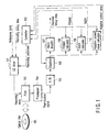
- FIG. 1 is a block diagram showing an optical disk recording/reproducing apparatus.
- Recording binary data is converted into a series in which at least two "0s" or “1s” in the code bit series successively occur by use of a modulator (not shown) whose run length is "1".
- the recording binary data is converted into a recording wave according to a recording parameter output from a controller 102 by use of a laser diode (LD) driver 101.
- the recording wave of an electrical signal is converted into an optical signal by a pickup head (PUH) 103 and then applied onto an optical disk 100.
- PH pickup head
- marks are formed according to application of the laser light.
- As the optical disk 100 a land & groove recording type optical disk is used.
- information recorded on the optical disk 100 is reproduced as a weak analog signal by use of the PUH 103.
- the analog signal is amplified to a sufficiently high signal level by use of a preamplifier 104 and then converted into a digital signal sampled at a constant frequency by an analog-digital converter (ADC) 105.
- a digital reproduction signal is converted into a signal which is synchronized with a channel clock in an equalizer 106 containing a phase-locked loop (PLL) and, at the same time, it is converted into an equalized reproduction signal of a characteristic which is close to the PR(1,2,2,2,1) characteristic.
- the equalization coefficient used in the equalizer 106 is derived from the signal which is synchronized with the channel clock and decoded binary data.
- a pass is selected.
- the Euclidean distance of the pass with respect to the equalized reproduction signal is minimum and a code bit series corresponding to the selected pass is output as decoded binary data.
- the equalized reproduction signal and decoded binary data are input to a PRSNR (Partial Response Signal to Noise Ratio) calculator 108 and an evaluation value PRSNR is measured. Further, the equalized reproduction signal and decoded binary data are also input to an SbER (Simulated bit Error Rate) calculator 109 and an evaluation value SbER is measured. In addition, the equalized reproduction signal and decoded binary data are input to an adaptive control value calculator 110 and an adaptive control value is measured. The measured PRSNR, SbER and adaptive control value are supplied to the controller 102 and the evaluation value is evaluated. Further, the recording parameter is adjusted and modified. In addition, the first and second recording parameter adjusting methods are selectively switched. Although not shown in the drawing, an alarm signal is output to warning means as required.
- PRSNR Partial Response Signal to Noise Ratio
- SbER Simulated bit Error Rate
- the relation between the recording parameter and the evaluation value is measured in the controller 102, the optimum value of the evaluation values is derived based on the measurement result and the recording parameter which causes the evaluation value to be set as the optimum value can be determined as an adjusted value.
- the relation between the recording parameter and the evaluation value is measured, the optimum value of the evaluation values is derived based on the result of measurement and a certain value smaller than or equal to the optimum value may be set as a specified value. Then, the upper limit value and lower limit value of the recording parameters which satisfy the specified value are determined and an intermediate value of the upper limit and lower limit values is set as an adjusted value of the recording parameter.
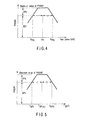
- FIG. 2 shows the configurations of recording binary data a and recording waveform b. Marks are formed on the optical disk in correspondence to high levels of the recording binary data ("a" in FIG. 2).
- the recording waveform b contains a single pulse to record the shortest 2T mark. As a mark to be recorded becomes longer, the number of pulses of the recording waveform b becomes larger.
- the recording parameters are individually set when information is recorded on the land track and when information is recorded on the groove track. The recording parameters are shown in the TABLE 1.
- Values different for respective mark lengths can be set for T LC . Further, values different for respective mark lengths and the lengths of spaces preceding the marks can be set for T SFP . Likewise, values different for respective mark lengths and the lengths of spaces succeeding to the marks can be set for T ELP .
- the adaptive control parameters are shown in the TABLE 2.
- the recording parameter adjusting procedure is explained. Since the adjusting procedures for the land track recording parameters and groove track recording parameters are the same, only the land track recording parameter adjusting procedure is explained here. The outline of the adjusting procedure is shown in FIG. 3.
- An adjusting method of setting the maximum value of PRSNR derived in the procedure 5 to P P1 may be used.
- the specified value is set to 80% or more of the maximum value, but this is not limitative.
- PRSNR is set as an evaluation value, but SbER may be used as an evaluation value. When SbER is used as the evaluation value, the peak power and bias power 1 are adjusted to make the SbER value smaller.
- An adjusting method for setting the maximum value of PRSNR derived in the procedure 4 to T MP(cal) may be used.
- the specified value is set to 80% or more of the maximum value, but this is not limitative.
- PRSNR is set as an evaluation value, but SbER may be used as an evaluation value.
- T MP is adjusted to make the SbER value smaller.
- An adjusting method for setting the maximum value of PRSNR derived in the procedure 4 to T SFP2T and setting the maximum value of PRSNR derived in the procedure 9 to T SFP3T may be used.
- the specified value is set to 80% or more of the maximum value, but this is not limitative.
- PRSNR is set as an evaluation value, but SbER may be used as an evaluation value. When SbER is used as the evaluation value, T SFP is adjusted to make the SbER value smaller.
- PRSNR is set more than or equal to 15.0 and SbER is set less than or equal to 5 ⁇ 10 -5 , but this invention is not limited to this case.
- PRSNR may be set more than or equal to 13.0 and SbER may be set less than or equal to or 5 ⁇ 10 -4 .
- the procedures are repeatedly performed until all of the adaptive control values are set to 0, but this invention is not limited to this case.
- the procedures may be repeatedly performed until 80% or more of the control values are set to 0.
- the procedures may be repeatedly performed until the control values are set to as close to 0 as possible.
- the number of repetition times is previously specified and the procedures may be repeatedly performed by the specified number of times.
- the adaptive control value is set to one of three types of [-1, 0, +1], but this invention is not limited to this case.
- the adaptive control value is set to one of five types of [-2, -1, 0, +1, +2].
- ⁇ T is set to T/32, but this is not limitative and ⁇ T may be set to T/16, for example.
- the first half is a first recording parameter adjusting method and is one of or both of an adjusting method which is independent of a recording data bit string and an adjusting method which is dependent on the run length (consecutive length) of a code bit "1" of the recording data bit string.
- the latter half is a second recording parameter adjusting method and is an adjusting method which is dependent on the run length of a code bit "1" of the recording data bit string and the run length of a code bit "0" adjacent thereto.
- PRSNR is set equal to or more than 15.0 and SbER is set equal to or less than 5 ⁇ 10 -5 , but this invention is not limited to this case.
- PRSNR may be set equal to or more than 13.0 and SbER may be set equal to or less than 5 ⁇ 10 -4 .
- PRSNR used for calculation of the recording parameters is explained.
- a detection error tends to occur in the Viterbi decoding process when the Euclidean distance between passes is short.
- the Euclidean distance between the passes corresponds to a signal component in a system using the PRML identification system.
- the influence corresponds to a noise component for the pattern 1.
- the influences correspond to noise components for the patterns 2, 3.
- the signal/noise ratio S1 of the pattern 1 can be given as follows.
- the signal/noise ratios S2, S3 of the patterns 2, 3 can be given as follows.
- the lowest one of S1, S2, S3 is used as PRSNR.
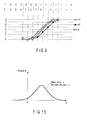
- FIG. 8 A concrete internal block diagram of the PRSNR calculator 108 is shown in FIG. 8. As PRSNR is higher, the signal quality becomes higher, and therefore, the recording parameter may be adjusted so as to increase PRSNR.
- the signal/noise ratios of the patterns 4, 5, 6 can be derived in the same manner. Therefore, the signal/noise ratios of the patterns 1 to 6 are derived and the minimum value thereof can be used as PRSNR. However, in general, the frequency of occurrence of the patterns 4, 5, 6 is lower than that of the patterns 1, 2, 3. For easy measurement, in this embodiment, PRSNR is derived based on the patterns 1, 2, 3. Further, the signal/noise ratio of a pattern having a larger Euclidean distance between the passes can be derived in the same manner. In order to more precisely evaluate the signal quality, PRSNR can be derived together with the signal/noise ratio with respect to the patterns.
- a reference symbol 301 denotes a target signal generator which generates a target signal by use of the PR waveform and decoded binary data.
- a reference symbol 302 denotes a comparator which compares the target signal with an equalized reproduction signal to derive an equalized difference. The above operation process is performed by use of the equalized difference. The autocorrelation of the equalized difference is calculated and weighted by a multiplier by using ⁇ i. Then, the sum of the correlation values is derived.
- the probability F(0) that T is erroneously identified as F can be expressed as follows.
- an estimated value SbER of bER (bit error) can be derived as follows.
- SbER ⁇ C T ⁇ F ( 0 ) ⁇ H T,F where C T indicates the rate of occurrence of the pattern T and H T,F indicates a humming distance.
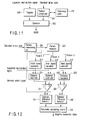
- FIG. 11 is a concrete internal block diagram of the SbER calculator 109.
- Decoded binary data is input to a pattern comparator 401.
- the pattern comparator 401 compares patterns recorded in a reference TABLE 402 with the decoded binary data to detect a pattern which tends to be erroneously identified.
- the detected pattern is input to an operator 403.
- the reproduction signal is input to the operator 403 via a register 404.
- FIG. 12 is an internal block diagram of the adaptive control value calculator 110.
- Several types of preset patterns (pattern 1) are registered in a pattern determining unit 501 and a signal indicating one of the registered patterns is output when decoded binary data coincides with the registered pattern.
- a pattern memory 502 three types of patterns (pattern 1, pattern 2, pattern 3) registered therein are output according to the signal from the pattern determining unit.
- ideal signal calculators 511, 512, 513 passes corresponding to the PR(1,2,2,2,1) characteristic are formed based on the output patterns.
- distance calculators 521, 522, 523 passes and Euclidean distances (which are respectively set to E1, E2, E3) between the passes and the equalized reproduction signal are calculated.
- the difference between the Euclidean distances E2 and E1 and the difference between the Euclidean distances E3 and E1 are calculated in difference calculators 531, 532 and stored in distance difference memories 541, 542.
- the locations of the distance difference memories in which the differences are to be stored are determined depending on the output signal of the pattern determining unit.
- parameter calculating means 550 calculates an adaptive control value based on data stored in the distance difference memories.
- the lengths of marks and spaces are divided into three types of 2T/3T/ ⁇ 4T and an adaptive control value is calculated for each pattern with respect to the mark and space.
- the contents of the pattern 1, pattern 2, pattern 3 stored in the pattern memory are shown in the TABLE 5.
- First and second columns of the TABLE 5 correspond to the adaptive control parameters of the TABLE 2.
- the second row of the TABLE 5 shows a pattern used to derive an adaptive control value for 2T space/2T mark recording.
- the pattern 2 is obtained by changing a portion corresponding to the code bit string "10" (or "01") appearing in the pattern 1 to "00" (or "11").
- the pattern 3 is obtained by changing a portion corresponding to the code bit string "10" (or “01") appearing in the center of the pattern 1 to "11" (or “00").
- "?" expresses a code bit “0” or “1”. If “?" in the pattern 1 is “0” ("1"), "?" in a corresponding portion of each of the patterns 2, 3 is also “0” ("1").
- the second row of the TABLE 5 is expanded as shown in the TABLE 6.
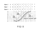
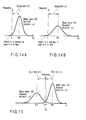
- the basic concept of the adaptive control value calculating operation of this invention is shown in FIGS. 13, 14A, 14B and 15.
- the distributions of D2, D3 are expressed as shown in FIGS. 14A, 14B.
- a region in which the distribution becomes equal to or smaller than "0" corresponds to an identification error.
- the pattern 2 is selected when the distribution is equal to or less than "0".
- the pattern 3 is selected when the distribution is equal to or less than "0".
- Mgn3 M2/ ⁇ 3
- the unit of Ec is a Euclidean distance.
- the unit of the adaptive control parameters T SFP , T ELP is time. It is difficult to convert the Euclidean distance to time.
- the adaptive control parameters may be adjusted based on Ec as follows.
- a dead zone is set at or near "0" and the adaptive control value is set to "0" if Ec lies in the dead zone. If Ec is larger than the dead zone, the adaptive control value is set to +1. On the other hand, if Ec is smaller than the dead zone, the adaptive control value is set to -1.
- the operation is repeatedly performed until all of the adaptive control values become "0", but this invention is not limited to this case.
- the operation may be repeatedly performed until 80% or more of the adaptive control values become "0".
- the operation may be repeatedly performed until the adaptive control values become approximately equal to "0".
- the number of repetition times is previously specified and the operation is repeatedly performed by a specified number of times.
- the adaptive control values are set to three types of [-1, 0, +1], but this is not limitative. For example, they may be set to five types of [-2, -1, 0, +1, +2] . Further, ⁇ T is set to T/32, but it is not limited to this case. For example, ⁇ T can be set to T/16.
- the second recording parameter adjusting procedure of this invention is explained. Since the adjusting procedure of the recording parameter for land tracks and the adjusting procedure of the recording parameter for groove tracks are the same, only the recording parameter adjusting procedure for land tracks is explained here. The outline of the adjusting procedure is shown in FIG. 16.
- An adjusting method of setting the maximum value of PRSNR derived in the procedure 5 to P P1 may be used.
- the specified value is set to 80% or more of the maximum value, but this is not limitative.
- PRSNR is set as an evaluation value, but SbER may be used as an evaluation value. When SbER is used as the evaluation value, the peak power and bias power 1 are adjusted to make the SbER value smaller.
- An adjusting method of setting the maximum value of PRSNR derived in the procedure 4 to T MP(cal) may be used.
- the specified value is set to 80% or more of the maximum value, but this is not limitative.
- PRSNR is set as an evaluation value, but SbER may be used as an evaluation value.
- T MP is adjusted to make the SbER value smaller.
- Step SA3 of FIG. 16 (Determination as to whether PRSNR and SbER Satisfy Specified Reference Value: Step SA3 of FIG. 16)
- PRSNR is set equal to or more than 15.0 and SbER is set equal to or less than 5 ⁇ 10 -5 , but this invention is not limited to this case.
- PRSNR may be set equal to or more than 13.0 and SbER may be set equal to or less than 5 ⁇ 10 -4 .
- the operation is repeatedly performed until all of the adaptive control values become "0", but this invention is not limited to this case.
- the operation may be repeatedly performed until 80% or more of the adaptive control values become "0".
- the operation may be repeatedly performed until the adaptive control values become approximately equal to "0" .
- the number of repetition times is previously specified and the operation may be repeatedly performed by a specified number of times.
- the adaptive control values are set to three types of [-1, 0, +1], but this is not limitative. For example, they may be set to five types of [-2, -1, 0, +1, +2]. Further, ⁇ T is set to T/32, but it is not limited to this case. For example, ⁇ T can be set to T/16.
- Step SA5 in FIG. 16 (Determination as to whether Optical Disk is Improper or not: Step SA5 in FIG. 16)
- PRSNR is set equal to or more than 15.0 and SbER is set equal to or less than 5 ⁇ 10 -5 , but this invention is not limited to this case.
- PRSNR may be set equal to or more than 13.0 and SbER may be set equal to or less than 5 ⁇ 10 -4 .
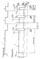
- a so-called multi-pulse waveform is used as a recording waveform.
- this invention is not limited to this case and a rectangular waveform such as a recording waveform ("b" in FIG. 17) may be used.
- "a" in FIG. 17 indicates recording binary data.
- the recording parameters are shown in the TABLE 7. Recording Parameter for Land Track Peak Power, Bias Power 1, Bias Power 2, T SFP , T ELP , T LC Recording Parameter for Groove Track Peak Power, Bias Power 1, Bias Power 2, T SFP , T ELP , T LC
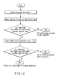
- the recording parameter adjusting procedure used when the rectangular wave is used as the recording wave is shown in FIG. 18 or 19.
- a waveform shown in FIG. 20 obtained by modifying the rectangular recording waveform can be used as the recording waveform "b".
- "a" in FIG. 20 is recording binary data.
- the recording wave to which this invention can be applied is not limited to the above case.
- a so-called land & groove recording type optical disk is used.
- this invention is not limited to this case and an optical disk in which information is recorded only on the land or groove can be used.
- the mark length and space length are classified into three groups of 2T, 3T and ⁇ 4T, but this invention is not limited to this case.
- the mark length and space length can be classified into four groups of 2T, 3T, 4T and ⁇ 5T.
- PR(1,2,2,2,1) is used, but this invention is not limited to this case.
- this invention can be applied to another PR class, for example, PR(1,2,2,1) or PR(3,4,4,3).
- optimum recording parameters can be derived by the optical disk recording/reproducing method of this invention.
- the recording parameter can be derived in a short period of time by use of the optical disk recording/reproducing method of this invention.
- An optical disk recording/reproducing apparatus which can correctly record/reproduce information can be provided by using a recording wave derived by use of the optical disk recording/reproducing method of this invention. Further, it is possible to provide an optical disk on which information is correctly recorded by recording information by use of a recording wave derived according to the optical disk recording/reproducing method of this invention.
Landscapes
- Physics & Mathematics (AREA)
- Optics & Photonics (AREA)
- Engineering & Computer Science (AREA)
- Signal Processing (AREA)
- Optical Recording Or Reproduction (AREA)
- Optical Head (AREA)
Applications Claiming Priority (2)
| Application Number | Priority Date | Filing Date | Title |
|---|---|---|---|
| JP2004166191A JP4160533B2 (ja) | 2004-06-03 | 2004-06-03 | 光ディスク記録再生方法及び光ディスク記録再生装置 |
| JP2004166191 | 2004-06-03 |
Publications (2)
| Publication Number | Publication Date |
|---|---|
| EP1603127A2 true EP1603127A2 (de) | 2005-12-07 |
| EP1603127A3 EP1603127A3 (de) | 2007-07-25 |
Family
ID=34939544
Family Applications (1)
| Application Number | Title | Priority Date | Filing Date |
|---|---|---|---|
| EP05103437A Withdrawn EP1603127A3 (de) | 2004-06-03 | 2005-04-27 | Aufzeichnungs- / Wiedergabeverfahren für optische Platte, Aufzeichnungs- / Wiedergabegerät für optische Platte, und optische Platte |
Country Status (6)
| Country | Link |
|---|---|
| US (1) | US7471601B2 (de) |
| EP (1) | EP1603127A3 (de) |
| JP (1) | JP4160533B2 (de) |
| KR (1) | KR100676434B1 (de) |
| CN (1) | CN1331123C (de) |
| TW (1) | TW200606872A (de) |
Cited By (4)
| Publication number | Priority date | Publication date | Assignee | Title |
|---|---|---|---|---|
| EP1964113A4 (de) * | 2005-12-20 | 2009-03-25 | Samsung Electronics Co Ltd | Verfahren und vorrichtung zur optimierung von schreibbedingungen sowie optisches aufzeichnungsmedium |
| EP2242053A1 (de) * | 2009-04-14 | 2010-10-20 | Hitachi Consumer Electronics Co., Ltd. | Anpassungsverfahren zur Zustandsaufzeichnung und optische Plattenvorrichtung |
| EP2249343A1 (de) * | 2009-05-08 | 2010-11-10 | Hitachi Consumer Electronics Co., Ltd. | Anpassungsverfahren zur Zustandsaufzeichnung und optische Plattenvorrichtung |
| EP2043102A4 (de) * | 2006-12-28 | 2011-07-06 | Panasonic Corp | Bewertungsverfahren für ein informationsaufzeichnungsmedium, informationsaufzeichnungsmedium, verfahren zur herstellung eines informationsaufzeichnungsmediums, signalverarbeitungsverfahren und zugangssteuerungsvorrichtung |
Families Citing this family (15)
| Publication number | Priority date | Publication date | Assignee | Title |
|---|---|---|---|---|
| US20070086315A1 (en) * | 2005-10-19 | 2007-04-19 | Mediatek Inc. | Optical disc apparatuses |
| ATE434296T1 (de) * | 2006-04-05 | 2009-07-15 | Sequans Comm | Verfahren zum dekodieren eines räumlich gemultiplexten signals und entsprechender empfänger |
| JP2007317343A (ja) * | 2006-04-28 | 2007-12-06 | Sharp Corp | 記録パラメータ設定装置、そのプログラムおよび該プログラムを記録したコンピュータ読取り可能な記録媒体、情報記録媒体、ならびに記録パラメータ設定方法 |
| JP4556912B2 (ja) * | 2006-05-29 | 2010-10-06 | Tdk株式会社 | 光記録媒体の記録条件設定方法 |
| JP4560009B2 (ja) | 2006-05-31 | 2010-10-13 | 株式会社東芝 | 光記録媒体、情報記録方法、および情報再生方法 |
| JP2008027501A (ja) * | 2006-07-20 | 2008-02-07 | Sanyo Electric Co Ltd | 光ディスクおよび光ディスク装置 |
| JP4900391B2 (ja) * | 2006-09-11 | 2012-03-21 | 日本電気株式会社 | 光学的情報記録再生装置及び記録マーク品質測定方法 |
| ATE466364T1 (de) * | 2007-02-05 | 2010-05-15 | Taiyo Yuden Kk | Verfahren zur anpassung der aufzeichnungsbedingungen für optische plattenaufzeichnungs-/-wiedergabesysteme, optische aufzeichnungswiedergabevorrichtung und optische platte |
| JPWO2008133133A1 (ja) * | 2007-04-16 | 2010-07-22 | 日本電気株式会社 | 光学的情報記録媒体への信号記録条件調整方法、情報記録再生装置 |
| JP2008287789A (ja) * | 2007-05-16 | 2008-11-27 | Toshiba Corp | 光ディスク装置及び光ディスク記録再生方法 |
| KR20090048635A (ko) * | 2007-08-02 | 2009-05-14 | 닛본 덴끼 가부시끼가이샤 | 광학적 정보 기록 매체에 대한 신호 기록 조건 조정 방법, 정보 기록 재생 장치 |
| TWI440027B (zh) * | 2009-01-22 | 2014-06-01 | Sunplus Technology Co Ltd | 光學儲存裝置及其寫入功率暫態的消除方法 |
| JP2011118961A (ja) * | 2009-12-01 | 2011-06-16 | Taiyo Yuden Co Ltd | データ記録評価方法,装置及びプログラム、並びに光情報記録媒体 |
| JP2011210371A (ja) * | 2011-07-29 | 2011-10-20 | Hitachi Ltd | 光ディスク記録装置、および、光ディスク記録方法。 |
| US8929017B2 (en) * | 2011-12-12 | 2015-01-06 | Lsi Corporation | Systems and methods for SNR measurement using equalized data |
Family Cites Families (16)
| Publication number | Priority date | Publication date | Assignee | Title |
|---|---|---|---|---|
| JPH03171437A (ja) | 1989-11-30 | 1991-07-24 | Matsushita Electric Ind Co Ltd | 信号記録方法と最適パワー設定装置 |
| JP2825959B2 (ja) * | 1990-10-02 | 1998-11-18 | 松下電器産業株式会社 | 最適パワー設定可能な光ディスク装置 |
| TW227022B (en) | 1992-11-18 | 1994-07-21 | Tzong-Biau Su | Apparatus for purifying and polarizing water |
| JP2636710B2 (ja) | 1993-10-30 | 1997-07-30 | 日本電気株式会社 | 書換え型光記録再生装置 |
| JPH07235150A (ja) * | 1994-02-24 | 1995-09-05 | Sony Corp | ディジタル信号記録再生方法及びディジタル信号記録再生装置 |
| KR100354732B1 (ko) | 1998-04-03 | 2002-11-18 | 삼성전자 주식회사 | 고밀도광기록기기를위한적응적인기록방법및그장치 |
| US6925040B1 (en) * | 1998-08-04 | 2005-08-02 | Hitachi, Ltd. | Information recording method, information recording medium and information recording apparatus |
| JP2000149262A (ja) * | 1998-11-13 | 2000-05-30 | Hitachi Ltd | 情報記録方法及び情報記録装置 |
| JP2000228066A (ja) * | 1999-02-05 | 2000-08-15 | Sony Corp | テープドライブ装置の調整方法、サーチ方法、及びテープドライブ装置 |
| CN1190779C (zh) * | 1999-03-19 | 2005-02-23 | 松下电器产业株式会社 | 光学信息记录方法和使用该方法在光学信息记录媒体中进行信息记录的光学信息记录装置 |
| JP2002025066A (ja) | 2000-06-30 | 2002-01-25 | Sony Corp | 情報記録再生装置 |
| JP4351813B2 (ja) * | 2001-04-20 | 2009-10-28 | 株式会社東芝 | 光ディスク装置 |
| US7038982B2 (en) * | 2001-09-27 | 2006-05-02 | Koninklijke Philips Electronics N.V. | Method and recording device for selecting an optimized write strategy and recording medium for use by the method |
| JP3958084B2 (ja) * | 2002-02-08 | 2007-08-15 | キヤノン株式会社 | 光学的記録再生方法 |
| JP3668202B2 (ja) * | 2002-03-13 | 2005-07-06 | 株式会社東芝 | 情報記録再生装置及びその信号評価方法 |
| JP2003317340A (ja) | 2002-04-26 | 2003-11-07 | Matsushita Electric Ind Co Ltd | 光磁気ディスク装置および磁壁移動型光磁気記録媒体 |
-
2004
- 2004-06-03 JP JP2004166191A patent/JP4160533B2/ja not_active Expired - Fee Related
-
2005
- 2005-04-27 EP EP05103437A patent/EP1603127A3/de not_active Withdrawn
- 2005-04-28 TW TW094113738A patent/TW200606872A/zh unknown
- 2005-05-24 KR KR1020050043553A patent/KR100676434B1/ko not_active Expired - Fee Related
- 2005-06-02 CN CNB2005100755159A patent/CN1331123C/zh not_active Expired - Fee Related
- 2005-06-03 US US11/143,996 patent/US7471601B2/en not_active Expired - Fee Related
Non-Patent Citations (1)
| Title |
|---|
| YUJI NAGAI, AKIHITO OGAWA, YUKATA KASHIHARA: "A New Method of Evaluating Signal Quality for Systems to which Partial response Maximum Likelihood Is Applied", JOURNAL OF APPLIED PHYSICS, vol. 42, no. Part1,2B, February 2003 (2003-02-01), pages 971 - 975, XP007908963 * |
Cited By (10)
| Publication number | Priority date | Publication date | Assignee | Title |
|---|---|---|---|---|
| EP1964113A4 (de) * | 2005-12-20 | 2009-03-25 | Samsung Electronics Co Ltd | Verfahren und vorrichtung zur optimierung von schreibbedingungen sowie optisches aufzeichnungsmedium |
| US7791999B2 (en) | 2005-12-20 | 2010-09-07 | Tdk Corporation | Writing condition optimizing method and apparatus, and optical recording medium |
| CN101300624B (zh) * | 2005-12-20 | 2011-02-02 | Tdk株式会社 | 写入条件优化方法和设备以及光记录介质 |
| EP2043102A4 (de) * | 2006-12-28 | 2011-07-06 | Panasonic Corp | Bewertungsverfahren für ein informationsaufzeichnungsmedium, informationsaufzeichnungsmedium, verfahren zur herstellung eines informationsaufzeichnungsmediums, signalverarbeitungsverfahren und zugangssteuerungsvorrichtung |
| US8254234B2 (en) | 2006-12-28 | 2012-08-28 | Panasonic Corporation | Information recording medium evaluation method, information recording medium, method for manufacturing information recording medium, signal processing method and access control apparatus |
| EP2242053A1 (de) * | 2009-04-14 | 2010-10-20 | Hitachi Consumer Electronics Co., Ltd. | Anpassungsverfahren zur Zustandsaufzeichnung und optische Plattenvorrichtung |
| US8085640B2 (en) | 2009-04-14 | 2011-12-27 | Hitachi Consumer Electronics Co., Ltd. | Adjusting method for recording condition and optical disc device |
| US8264932B2 (en) | 2009-04-14 | 2012-09-11 | Hitachi Consumer Electronics Co., Ltd. | Adjusting method for recording condition and optical disc device |
| EP2249343A1 (de) * | 2009-05-08 | 2010-11-10 | Hitachi Consumer Electronics Co., Ltd. | Anpassungsverfahren zur Zustandsaufzeichnung und optische Plattenvorrichtung |
| US8531932B2 (en) | 2009-05-08 | 2013-09-10 | Hitachi Consumer Electronics Co., Ltd. | Adjusting method for recording condition and optical disc device |
Also Published As
| Publication number | Publication date |
|---|---|
| US20050270939A1 (en) | 2005-12-08 |
| JP2005346847A (ja) | 2005-12-15 |
| CN1707632A (zh) | 2005-12-14 |
| CN1331123C (zh) | 2007-08-08 |
| KR20060046153A (ko) | 2006-05-17 |
| EP1603127A3 (de) | 2007-07-25 |
| US7471601B2 (en) | 2008-12-30 |
| TW200606872A (en) | 2006-02-16 |
| KR100676434B1 (ko) | 2007-02-01 |
| JP4160533B2 (ja) | 2008-10-01 |
Similar Documents
| Publication | Publication Date | Title |
|---|---|---|
| EP1603127A2 (de) | Aufzeichnungs- / Wiedergabeverfahren für optische Platte, Aufzeichnungs- / Wiedergabegerät für optische Platte, und optische Platte | |
| US7082566B2 (en) | Signal quality evaluation method, information recording/reproducing system, and recording compensation method | |
| KR101049695B1 (ko) | 기록 제어 장치, 기록 및 재생 장치, 및 기록 제어 방법 | |
| KR100951629B1 (ko) | 데이터 기록 평가 방법 및 광 디스크 기록 재생 장치 | |
| JP3697409B2 (ja) | 信号品質評価方法および記録補償方法 | |
| US7263050B2 (en) | Methods and systems for tuning write strategy parameters of an optical storage device | |
| US7636287B2 (en) | Reproduced signal equalizing method for optical information media and optical information reproducing/recording apparatus | |
| EP1443509A2 (de) | Verfahren zur Signalauswertung, Vorrichtung zur Informationsaufzeichung/-wiedergabe, Informationswiedergabevorrichtung und Informationsaufzeichnungsmedium | |
| EP2249343B1 (de) | Anpassungsverfahren zur Zustandsaufzeichnung und optische Plattenvorrichtung | |
| KR101116205B1 (ko) | 광디스크 장치 | |
| CN101553872A (zh) | 光学信息记录/重放装置和测量记录的标记的品质的方法 | |
| JP2003317256A (ja) | 多値データ記録再生装置 | |
| US8369199B2 (en) | Methods and systems for tuning at least one write strategy parameter of an optical storage device | |
| JP3822562B2 (ja) | 記録補償方法及び記録再生装置 | |
| US7760605B2 (en) | Optical information recording device, optical information recording method, and signal processing circuit | |
| JP3836863B2 (ja) | 情報記録再生装置 | |
| JP3875711B2 (ja) | 光ディスク | |
| KR20100132047A (ko) | 데이터 기록 평가 방법 및 광디스크 기록 재생 장치 | |
| EP1482499A1 (de) | Verfahren zur Bestimmung der Asymmetrie einer Aufzeichnung auf einem optischen Medium | |
| JP4068645B2 (ja) | 情報記録再生方法 | |
| JP2005332571A (ja) | 情報記録再生システムおよび装置 | |
| HK1115933A (en) | Data recording evaluation method and optical disk recording and reproduction device |
Legal Events
| Date | Code | Title | Description |
|---|---|---|---|
| PUAI | Public reference made under article 153(3) epc to a published international application that has entered the european phase |
Free format text: ORIGINAL CODE: 0009012 |
|
| 17P | Request for examination filed |
Effective date: 20050427 |
|
| AK | Designated contracting states |
Kind code of ref document: A2 Designated state(s): AT BE BG CH CY CZ DE DK EE ES FI FR GB GR HU IE IS IT LI LT LU MC NL PL PT RO SE SI SK TR |
|
| AX | Request for extension of the european patent |
Extension state: AL BA HR LV MK YU |
|
| PUAL | Search report despatched |
Free format text: ORIGINAL CODE: 0009013 |
|
| AK | Designated contracting states |
Kind code of ref document: A3 Designated state(s): AT BE BG CH CY CZ DE DK EE ES FI FR GB GR HU IE IS IT LI LT LU MC NL PL PT RO SE SI SK TR |
|
| AX | Request for extension of the european patent |
Extension state: AL BA HR LV MK YU |
|
| 17Q | First examination report despatched |
Effective date: 20070910 |
|
| AKX | Designation fees paid |
Designated state(s): DE FR GB |
|
| STAA | Information on the status of an ep patent application or granted ep patent |
Free format text: STATUS: THE APPLICATION IS DEEMED TO BE WITHDRAWN |
|
| 18D | Application deemed to be withdrawn |
Effective date: 20091119 |