EP1605471A2 - Ecran intensificateur radiographique - Google Patents
Ecran intensificateur radiographique Download PDFInfo
- Publication number
- EP1605471A2 EP1605471A2 EP05012224A EP05012224A EP1605471A2 EP 1605471 A2 EP1605471 A2 EP 1605471A2 EP 05012224 A EP05012224 A EP 05012224A EP 05012224 A EP05012224 A EP 05012224A EP 1605471 A2 EP1605471 A2 EP 1605471A2
- Authority
- EP
- European Patent Office
- Prior art keywords
- radiographic
- radiographic intensifying
- intensifying
- particles
- screen
- Prior art date
- Legal status (The legal status is an assumption and is not a legal conclusion. Google has not performed a legal analysis and makes no representation as to the accuracy of the status listed.)
- Withdrawn
Links
Images

Classifications
-
- G—PHYSICS
- G21—NUCLEAR PHYSICS; NUCLEAR ENGINEERING
- G21K—HANDLING OF PARTICLES OR IONISING RADIATION NOT OTHERWISE PROVIDED FOR; IRRADIATION DEVICES; GAMMA RAY OR X-RAY MICROSCOPES
- G21K4/00—Conversion screens for the conversion of the spatial distribution of X-rays or particle radiation into visible images, e.g. fluoroscopic screens
Definitions
- the present invention relates to a radiographic intensifying screen.
- the radiation image-forming method in which a radiographic intensifying screen (radiographic intensifying sheet) is used in combination with a radiographic film, has been hitherto adopted in radiographic medical diagnosis and industrial radiographic inspection such as non-destructive inspection.
- the screen is placed on one or both surface of the radiographic film, which is then exposed to radiation such as X-rays, ⁇ -rays or electron beams having passed through an object or having radiated from an object, so that an image is formed on the film.
- radiation of high energy such as X-rays or ⁇ -rays is applied to an object (sample) and an image according to spatial energy distribution of the radiation passed through the object is visualized on an industrial radiographic film to examine inner structure of the object or to check defects of the object.
- the object generally is so thick that an intensifying screen having as high intensifying efficiency as possible is used so as to shorten the exposure time or to lower the radiation dose in the inspection.
- the industrial radiographic film is sometimes placed at a short distance from the object so that the radiation passed through the object may not form a blurry image on the film.
- the film generally is postured parallel to the outer surface of the object.
- the radiographic intensifying screen is required to be flexible, and a cassette in which the film and the screen are encased is often made of flexible material such as plastics, rubber or black paper.
- an intensifying screen in which a metal sheet such as tin foil is provided on a support is often used (see, "Handbook of Non-Destructive Inspection, new edition (Japanese)", written by The Japanese Society for Non-Destructive Inspection (JSNDI), published by Nikkan Kogyou Shinbun, Ltd., 1978, pp. 275-276).
- the metal sheet such as tin foil intensifies high-energy radiation well, impairs image quality little, and is relatively flexible.
- lead foil remarkably intensifies the radiation, and is flexible and relatively inexpensive.
- the intensifying screen comprising lead foil is flexible but liable to cause plastic deformation when it is used repeatedly.
- E94 discloses a radiographic intensifying screen for industrial radiographic inspection.
- copper, gold, tantalum and lead oxide as well as lead foil are described as materials for the intensifying screen.
- An object of the present invention is to provide a radiographic intensifying screen having high intensifying efficiency and excellent flexibility but causing no environmental problem.
- the present inventors have found that a radiographic intensifying screen suitable for high energy radiation used in industrial radiographic inspection can be obtained if the radiographic intensifying function layer is made of a binder and therein-dispersed fine particles of metal and/or metal compounds (such as tungsten and/or compounds thereof) having good intensifying efficiency.
- the present invention resides in a radiographic intensifying screen comprising at least one radiographic intensifying function layer, wherein the radiographic intensifying function layer comprises a binder and radiographic intensifying particles, the radiographic intensifying particles being capable of absorbing a radiation and then not emitting a light in ultraviolet or visible wavelength region but emitting secondary electrons, secondary X-rays, secondary ⁇ -rays or combinations thereof, the particles comprising at least one metal or metal compound, the metal being selected from the group consisting of gold, tungsten, tantalum, barium, tin, silver, molybdenum, niobium, zirconium, zinc, copper, nickel, cobalt, iron, chromium, vanadium, and titanium.
- the invention further resides in a radiation image-forming method comprising the steps of: combining a radiographic film and the radiographic intensifying screen of the invention to give a combined body; and irradiating the combined body with radiation having passed through an object, having been diffracted or scattered by an object or having radiated from an object, whereby the film is exposed to secondary electrons emitted from the radiographic intensifying function layer of the screen and an image according to spatial energy distribution of the radiation is produced on the film.
- the present invention makes it possible to produce a highly effective and flexible radiographic intensifying screen at a relatively small cost.
- effectively intensifying radiation metals and metal compounds are often expensive or difficult to form into foil.
- the metals are used in the form of fine particles in the invention.
- the intensifying screen of the invention causes environmental pollution. Therefore, the radiographic intensifying screen of the invention is advantageously used in radiographic processes with high energy radiation, such as industrial radiographic inspection.
- Preferred embodiments of the radiographic intensifying screens according to the invention are as follows.
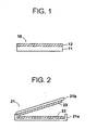
- Fig. 1 is a sectional view schematically illustrating a representative structure of the intensifying screen according to the invention.
- the intensifying screen 10 comprises a support 11 and a radiographic intensifying function layer 12.
- the function layer 12 comprises a binder and particles intensifying radiation (namely, radiographic intensifying particles) dispersed therein.
- the radiographic intensifying particles are particles capable of absorbing radiation and emitting secondary electrons, and the particles contain at least one metal selected from the group consisting of gold, tungsten, tantalum, barium, tin, silver, molybdenum, niobium, zirconium, zinc, copper, nickel, cobalt, iron, chromium, vanadium and titanium.
- the metal may be in the form of a metal compound or a mixture thereof. Examples of the metal compounds include oxides (e.g., tungsten oxides (WO 3 , WO 4 ), molybdenum oxide (MoO 2 )), and tungsten carbide (WC).
- the metal compound and the mixture of metal and metal compound preferably contain the metal in a content of 50 wt.% or more.
- the radiographic intensifying particles are preferably made of a tungsten metal, tungsten compound (e.g., WO 4 ) or a mixture thereof.
- tungsten metal e.g., WO 4
- the screen of the invention can be produced at relatively small cost since powdery tungsten is used.
- the radiographic intensifying particles preferably have a mean size in the range of 0.3 ⁇ m to 20 ⁇ m. If the sizes are larger than 20 ⁇ m, the resultant radiation image often has such uneven density that the sharpness decreases.
- the binder preferably is an organic polymer material in consideration of flexibility.
- the organic polymer materials include synthetic polymers such as nitrocellulose, ethyl cellulose, cellulose acetate, polyvinyl butyral, linear polyester, polyvinyl acetate, vinylidene chloride-vinyl chloride copolymer, vinyl chloride-vinyl acetate copolymer, polyalkyl (meth)acrylate, polycarbonate, polyurethane, cellulose acetate butyrate, polyvinyl alcohol and thermoplastic elastomers; and natural polymers such as proteins (e.g., gelatin), polysaccharides (e.g., dextran) and gum arabic. These polymers may be crosslinked with a crosslinking agent.
- the spatial packing ratio of the radiographic intensifying particles in the intensifying function layer 12 generally is 40 vol.% or more, preferably 60 vol.% or more.
- a ratio between the intensifying particles and the binder (former:latter) in the function layer generally is in the range of 10:1 to 100:1 by weight.
- the thickness of the intensifying function layer 12 depends on penetrating power of used radiation, but generally is in the range of 5 to 1,000 ⁇ m if the screen is placed on the incident side of the film. If the screen is placed on the opposite (back) side, the thickness of the function layer generally is in the range of 5 to 3,000 ⁇ m. In the industrial radiographic method, the function layer of the screen on the back side is generally thicker than that on the incident side. Further, if placed on the incident side, the screen having too thick a function layer absorbs radiation too much and accordingly lowers the intensifying efficiency.
- the radiographic intensifying screen has an intensifying function layer made of a binder and intensifying particles
- the intensifying screen of the invention is more flexible than a conventional intensifying screen comprising metal foil. Accordingly, in a radiographic method, the intensifying screen of the invention can be easily deformed (or curved) parallel to the outer surface of the object. Further, the intensifying screen of the invention can be well in contact with a radiographic film, and accordingly the surface of the intensifying screen is resistant to scratch.
- the radiographic intensifying screen of the invention is not restricted to Fig. 1, and can have various auxiliary layers described later such as a protective layer.
- the radiographic intensifying screen of the invention can be produced, for example, in the following manner.
- the support generally is a flexible sheet or film having a thickness of 50 ⁇ m to 1 mm.
- materials for the support include resins such as polyethylene terephthalate, polycarbonate, polyethylene naphthalate, acrylic resin, vinyl chloride resin, polyethylene and polyurethane; baryta paper; resin-coated paper; ordinary paper; wood; and metals and alloys such as iron and aluminum.
- auxiliary layers such as a subbing layer and an electro-conductive layer can be formed. Further, many fine concaves and convexes can be formed on the surface of the support.
- the radiographic intensifying function layer comprising radiographic intensifying particles is provided.
- the intensifying particles and the binder are dispersed or dissolved in an appropriate organic solvent to prepare a coating dispersion.
- a ratio between the particles and the binder in the solution generally is in the range of 10:1 to 100:1 (by weight), preferably in the range of 10:1 to 50:1 (by weight).
- solvent examples include lower aliphatic alcohols, chlorinated hydrocarbons, ketones, esters, ethers, and mixtures thereof.
- the coating dispersion can contain various additives such as a dispersing agent, a plasticizer for enhancing bonding between the binder and the particles, an anti-yellowing agent for preventing the function layer from undesirable coloring, a hardening agent, and a crosslinking agent.
- the prepared coating dispersion is then evenly spread on a surface of the support by means of coating means, and dried to form the radiographic intensifying function layer.
- the thickness of the intensifying function layer is determined according to various conditions such as characteristics of the desired intensifying screen, properties of the intensifying particles and the mixing ratio between the binder and the particles, but generally is in the range of 5 to 1,000 ⁇ m, preferably in the range of 10 to 500 ⁇ m.
- intensifying function layer can be compressed by means of, for example, a calendering machine so that the packing ratio of the intensifying particles in the layer can be further increased.
- the intensifying function layer does not always need to be a single layer, and may consist of two or more sub-layers.
- the sub-layers can differ in the intensifying particles in regard to the component or the particle size or in the ratio between the particles and the binder. The ratio can be optionally determined.
- the function layer beforehand formed on another substrate temporary support
- a protective layer is preferably provided on the intensifying function layer to ensure good handling of the intensifying screen in transportation and to avoid deterioration.
- the protective layer is chemically stable, physically strong, and of high moisture proof for protecting the screen from chemical deterioration and physical damage.
- the protective layer can be provided by coating the intensifying function layer with a solution in which a transparent organic polymer is dissolved in an appropriate solvent, by placing a beforehand prepared organic polymer film as the protective sheet on the intensifying function layer with an adhesive, or by depositing vapor of inorganic compounds on the function layer.
- Various additives can be contained in the protective layer. Examples of the additives include a slipping agent (e.g., powders of perfluoroolefin resin and silicone resin) and a crosslinking agent (e.g., polyisocyanate).
- the thickness of the protective layer is generally in the range of 1 to 20 ⁇ m, preferably in the range of 1 to 7 ⁇ m.
- a fluororesin layer can be provided on the protective layer.
- the radiographic intensifying screen of the invention can be produced.
- the intensifying screen of the invention can be in known various structures.
- Fig. 2 is a sectional view schematically illustrating a representative structure (planar box type) of the radiographic cassette.
- the radiographic cassette 21 consists of a body 21a and a lid 21b, which are partly combined so that the lid 21b can be opened or closed.
- radiographic intensifying screens 22, 23 are fixed or placed, respectively.
- Each of the intensifying screens 22, 23 has the structure shown in Fig. 1 according to the invention.
- the body 21a and the lid 21b of the cassette 21 are made of light-shielding but highly radiation-transmittable material such as aluminum and bakelite.
- Fig. 3 is a sectional view schematically illustrating another representative structure (light-shielding bag type) of the radiographic cassette.
- the light-shielding bag 21c radiographic intensifying screens 22, 23 are placed as shown in Fig. 3.
- the opening of the bag 21c is generally closed by folding up as shown in Fig. 3 to prevent light from coming into the bag.
- a radiographic film 24 is encased in the cassette 21 or 21c. As shown in Fig. 4, in the cassette 21 or 21c, the radiographic film 24 is placed between the intensifying screens 22, 23 so as to keep in contact with them.
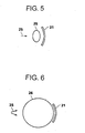
- Figs. 5 and 6 are top views schematically illustrating a radiation image-forming method of the invention.
- the cassette 21 containing a radiographic film is deformed to form a curve and placed parallel to the outer surface of the sample (object) 26.
- the sample 26 is irradiated with radiation 25.
- the radiation is, for example, X-rays or ⁇ -rays. If the sample 26 by itself emits radiation such as ⁇ -rays, ⁇ -rays or electron beams, it is not necessary to irradiate the sample 26 with radiation.
- the radiation having passed through the sample 26 comes into the cassette 21 to reach the intensifying screen 22, and is partly absorbed by the intensifying function layer of the intensifying screen 22.
- the intensifying function layer emits secondary electrons, to which the neighboring radiographic film 24 is exposed.
- the other portion of radiation still passes through the screen 22 and the film 24 to reach the back-side intensifying screen 23, and is absorbed by the intensifying function layer of the screen 23.
- the intensifying function layer of the back-side screen also emits secondary electrons, to which the neighboring radiographic film 24 is again exposed. Further, the radiographic film 24 is directly exposed to the radiation. In this way, an image according to spatial energy distribution of the radiation having passed through the sample is formed on the radiographic film 24.
- the radiographic cassette is not restricted to the embodiments described above.
- shock-absorbing material can be provided between the screen and the casing body and between the screen and the lid so that the radiographic film can be closely in contact with the screens.
- only one intensifying screen can be placed on the bottom of the body.
- the radiation image-forming method of the invention is also not restricted to the embodiments shown in Fig. 5.
- Various known embodiments can be adopted as long as the intensifying screen of the invention closely in contact with the radiographic film is irradiated with radiation. Accordingly, the image-forming method of the invention can be used in various radiographic processes.
- Fine particles of tungsten metal (radiographic intensifying particles, particle sizes: 1.9 to 7.5 (average: 5.2) ⁇ m) and vinyl chloride-vinyl acetate copolymer (binder) were added to ethyl acetate, and mixed and dispersed to prepare a coating dispersion (weight ratio of particles/binder: 50/1).
- the coating dispersion was then spread on a polyethylene terephthalate sheet (support, thickness: 250 ⁇ m) by means of a coating machine, and dried to form a radiographic intensifying function layer (thickness: 32 ⁇ m).
- a radiographic intensifying screen of the invention comprising the support and the intensifying function layer (shown in Fig. 1) was produced.
- Example 1 The procedure of Example 1 was repeated except for changing the sizes of intensifying particles, the weight ratio between the particles and the binder and/or the thickness of intensifying function layer into those set forth in Table 1, to produce radiographic intensifying screens of the invention.
- Example 1 The procedure of Example 1 was repeated except that the intensifying function layer was replaced with a sheet of lead foil (whose thickness is set forth in Table 1) fixed with an adhesive on the support, to produce conventional radiographic intensifying screens.
- the intensifying function layer was replaced with a sheet of lead foil (whose thickness is set forth in Table 1) fixed with an adhesive on the support, to produce conventional radiographic intensifying screens.
- radiographic intensifying screen produced in each of the Examples and Comparison Examples was combined with X-ray film, and its intensifying efficiency (film density) was measured. In addition, the flexibility of the screen (namely, whether the screen was broken or not when curved) was evaluated.
- the intensifying screen was kept in contact with industrial X-ray film (IX100, Fuji Photo Film Co., Ltd.), the radiographic method was carried out under each following condition (A) to (D). After exposed to radiation, the film was subjected to the standard development treatment to form an image. The transmittance of the film was measured to evaluate how densely the image was formed, and thereby the film optical density was obtained. On the basis of the obtained film optical density, the intensifying efficiency was estimated.
- industrial X-ray film IX100, Fuji Photo Film Co., Ltd.
- the intensifying screen was deformed to form a curve by hand, to test whether the screen was easily curved or not.
- Fine particles of simple tungsten metal (radiographic intensifying particles, particle sizes: 1.9 to 7.5 (average: 5.2) ⁇ m) and polyethylene (binder) were added to ethyl acetate, and mixed and dispersed to prepare a coating solution (weight ratio of particles/binder: 5/1).
- the coating solution was then spread to coat a polyethylene terephthalate sheet (support, thickness: 250 ⁇ m) by means of a coating machine, and dried to form a radiographic intensifying function layer (thickness: 180 ⁇ m).
- a radiographic intensifying screen of the invention comprising the support and the intensifying function layer (shown in Fig. 1) was produced.
- the thus-produced intensifying screen was evaluated in the same manner as described above. As a result, it was confirmed that the intensifying screen also had a high intensifying efficiency and excellent flexibility.
Landscapes
- Physics & Mathematics (AREA)
- Engineering & Computer Science (AREA)
- General Engineering & Computer Science (AREA)
- High Energy & Nuclear Physics (AREA)
- Conversion Of X-Rays Into Visible Images (AREA)
- Silver Salt Photography Or Processing Solution Therefor (AREA)
- Luminescent Compositions (AREA)
- Radiography Using Non-Light Waves (AREA)
Applications Claiming Priority (2)
| Application Number | Priority Date | Filing Date | Title |
|---|---|---|---|
| JP2004170124A JP2005351666A (ja) | 2004-06-08 | 2004-06-08 | 放射線増感スクリーンおよび放射線画像形成方法 |
| JP2004170124 | 2004-06-08 |
Publications (2)
| Publication Number | Publication Date |
|---|---|
| EP1605471A2 true EP1605471A2 (fr) | 2005-12-14 |
| EP1605471A3 EP1605471A3 (fr) | 2008-03-12 |
Family
ID=35004224
Family Applications (1)
| Application Number | Title | Priority Date | Filing Date |
|---|---|---|---|
| EP05012224A Withdrawn EP1605471A3 (fr) | 2004-06-08 | 2005-06-07 | Ecran intensificateur radiographique |
Country Status (3)
| Country | Link |
|---|---|
| US (1) | US20060038134A1 (fr) |
| EP (1) | EP1605471A3 (fr) |
| JP (1) | JP2005351666A (fr) |
Families Citing this family (1)
| Publication number | Priority date | Publication date | Assignee | Title |
|---|---|---|---|---|
| US7700922B2 (en) * | 2007-07-23 | 2010-04-20 | Fujifilm Corporation | Cassette device and cassette storage bag for cassette device |
Citations (4)
| Publication number | Priority date | Publication date | Assignee | Title |
|---|---|---|---|---|
| US3584216A (en) * | 1968-09-12 | 1971-06-08 | Bendix Corp | Radiographic intensifying screen |
| US4835396A (en) | 1987-01-21 | 1989-05-30 | Fuji Photo Film Co., Ltd. | Radiographic intensifying screen and radiation image producing method |
| EP0989566A1 (fr) | 1997-05-06 | 2000-03-29 | Kabushiki Kaisha Toshiba | Papier intensifiant les rayonnements, recepteur de rayonnements et appareil de controle des rayonnements utilisant le papier |
| US20020043627A1 (en) | 1998-06-26 | 2002-04-18 | Agfa-Gevaert | X-ray luminescent article offering improved film sharpness |
Family Cites Families (5)
| Publication number | Priority date | Publication date | Assignee | Title |
|---|---|---|---|---|
| US2856535A (en) * | 1957-05-31 | 1958-10-14 | Haloid Xerox Inc | Increasing speed in xeroradiography |
| FR1564714A (fr) * | 1968-02-22 | 1969-04-25 | ||
| BE792387A (nl) * | 1971-12-31 | 1973-06-07 | Agfa Gevaert Nv | Versterkingsschermen voor rontgenfotografie |
| DE2912668A1 (de) * | 1979-03-30 | 1980-10-02 | Agfa Gevaert Ag | Vorrichtung zum halten von blattfoermigen filmen |
| WO2004077097A2 (fr) * | 2003-02-27 | 2004-09-10 | Jp Laboratories Inc. | Dosimetre d'alerte instantane de rayonnement a indication automatique personnel et de zone |
-
2004
- 2004-06-08 JP JP2004170124A patent/JP2005351666A/ja not_active Withdrawn
-
2005
- 2005-06-07 EP EP05012224A patent/EP1605471A3/fr not_active Withdrawn
- 2005-06-08 US US11/147,174 patent/US20060038134A1/en not_active Abandoned
Patent Citations (4)
| Publication number | Priority date | Publication date | Assignee | Title |
|---|---|---|---|---|
| US3584216A (en) * | 1968-09-12 | 1971-06-08 | Bendix Corp | Radiographic intensifying screen |
| US4835396A (en) | 1987-01-21 | 1989-05-30 | Fuji Photo Film Co., Ltd. | Radiographic intensifying screen and radiation image producing method |
| EP0989566A1 (fr) | 1997-05-06 | 2000-03-29 | Kabushiki Kaisha Toshiba | Papier intensifiant les rayonnements, recepteur de rayonnements et appareil de controle des rayonnements utilisant le papier |
| US20020043627A1 (en) | 1998-06-26 | 2002-04-18 | Agfa-Gevaert | X-ray luminescent article offering improved film sharpness |
Also Published As
| Publication number | Publication date |
|---|---|
| JP2005351666A (ja) | 2005-12-22 |
| US20060038134A1 (en) | 2006-02-23 |
| EP1605471A3 (fr) | 2008-03-12 |
Similar Documents
| Publication | Publication Date | Title |
|---|---|---|
| EP3084477B1 (fr) | Détecteur de panneau plat de radiographie possédant un écran aux rayons x de faible poids et son procédé de production | |
| JPS6324280B2 (fr) | ||
| JP3479574B2 (ja) | フロント側用放射線増感スクリーン及び放射線増感スクリーン組体 | |
| US6541773B1 (en) | Radiation image detecting apparatus | |
| JPS63220237A (ja) | 多重ラジオグラフ像の製造方法 | |
| EP0128592B1 (fr) | Ecran pour l'enregistrement d'une image obtenue par rayonnement | |
| US6359285B1 (en) | Stimulable phosphor sheet | |
| US8618512B2 (en) | Storage phosphor panel with overcoat comprising dye | |
| EP1605471A2 (fr) | Ecran intensificateur radiographique | |
| US6339224B1 (en) | Radiation intensifying screen and radiation receptor and radiation inspection apparatus using the intensifying screen | |
| US6479834B1 (en) | Double-side reading system for reproducing radiation image | |
| US5743977A (en) | Radiation image storage panel and its preparation | |
| JPS59142500A (ja) | 放射線像変換パネル | |
| US20080292060A1 (en) | X-ray imaging cassette for use in radiotherapy | |
| US6344657B1 (en) | Stimulable phosphor sheet for double-side reading system | |
| JP3269735B2 (ja) | 放射線像変換パネル及びその製造方法 | |
| GB1599924A (en) | Intensifying screens | |
| US6669364B2 (en) | Cassette assembly for use with roentgen apparatus with automatic exposure control | |
| JP2006250639A (ja) | 放射線像変換パネル | |
| EP1168062B1 (fr) | Assemblage de cassette d'un appareil rx avec contrôle automatique d'exposition | |
| EP0967620B1 (fr) | Article luminescent aux rayons X avec une netteté de film améliorée | |
| JPS5932900A (ja) | 放射線像変換シ−ト | |
| US7211942B1 (en) | Radiation image conversion panel | |
| JP2004264231A (ja) | 放射線画像変換パネル | |
| JPH11133192A (ja) | 放射線増感紙 |
Legal Events
| Date | Code | Title | Description |
|---|---|---|---|
| PUAI | Public reference made under article 153(3) epc to a published international application that has entered the european phase |
Free format text: ORIGINAL CODE: 0009012 |
|
| AK | Designated contracting states |
Kind code of ref document: A2 Designated state(s): AT BE BG CH CY CZ DE DK EE ES FI FR GB GR HU IE IS IT LI LT LU MC NL PL PT RO SE SI SK TR |
|
| AX | Request for extension of the european patent |
Extension state: AL BA HR LV MK YU |
|
| RAP1 | Party data changed (applicant data changed or rights of an application transferred) |
Owner name: FUJIFILM CORPORATION |
|
| PUAL | Search report despatched |
Free format text: ORIGINAL CODE: 0009013 |
|
| AK | Designated contracting states |
Kind code of ref document: A3 Designated state(s): AT BE BG CH CY CZ DE DK EE ES FI FR GB GR HU IE IS IT LI LT LU MC NL PL PT RO SE SI SK TR |
|
| AX | Request for extension of the european patent |
Extension state: AL BA HR LV MK YU |
|
| RIC1 | Information provided on ipc code assigned before grant |
Ipc: C09K 11/68 20060101ALI20080207BHEP Ipc: G21K 4/00 20060101AFI20051010BHEP |
|
| 17P | Request for examination filed |
Effective date: 20080508 |
|
| 17Q | First examination report despatched |
Effective date: 20080722 |
|
| AKX | Designation fees paid |
Designated state(s): BE DE FR GB |
|
| STAA | Information on the status of an ep patent application or granted ep patent |
Free format text: STATUS: THE APPLICATION IS DEEMED TO BE WITHDRAWN |
|
| 18D | Application deemed to be withdrawn |
Effective date: 20090730 |