EP1606190B1 - Verschlussvorrichtung für einen behälter für fliessfähige materialien - Google Patents
Verschlussvorrichtung für einen behälter für fliessfähige materialien Download PDFInfo
- Publication number
- EP1606190B1 EP1606190B1 EP04719489A EP04719489A EP1606190B1 EP 1606190 B1 EP1606190 B1 EP 1606190B1 EP 04719489 A EP04719489 A EP 04719489A EP 04719489 A EP04719489 A EP 04719489A EP 1606190 B1 EP1606190 B1 EP 1606190B1
- Authority
- EP
- European Patent Office
- Prior art keywords
- closure device
- duct
- sleeve
- intended
- conduit
- Prior art date
- Legal status (The legal status is an assumption and is not a legal conclusion. Google has not performed a legal analysis and makes no representation as to the accuracy of the status listed.)
- Expired - Lifetime
Links
- 239000012530 fluid Substances 0.000 title claims abstract description 17
- 239000000463 material Substances 0.000 claims abstract description 33
- 238000007789 sealing Methods 0.000 claims description 26
- 230000002093 peripheral effect Effects 0.000 claims description 9
- 238000003466 welding Methods 0.000 claims description 5
- 238000001746 injection moulding Methods 0.000 claims description 2
- 238000002347 injection Methods 0.000 description 3
- 239000007924 injection Substances 0.000 description 3
- 238000000034 method Methods 0.000 description 3
- 239000011324 bead Substances 0.000 description 2
- 239000011449 brick Substances 0.000 description 2
- 238000000465 moulding Methods 0.000 description 2
- 230000000007 visual effect Effects 0.000 description 2
- 235000013361 beverage Nutrition 0.000 description 1
- 238000004891 communication Methods 0.000 description 1
- 229910003460 diamond Inorganic materials 0.000 description 1
- 239000010432 diamond Substances 0.000 description 1
- 230000000694 effects Effects 0.000 description 1
- 210000000056 organ Anatomy 0.000 description 1
- 238000004806 packaging method and process Methods 0.000 description 1
- 239000000843 powder Substances 0.000 description 1
- 238000002604 ultrasonography Methods 0.000 description 1
- 238000011144 upstream manufacturing Methods 0.000 description 1
- XLYOFNOQVPJJNP-UHFFFAOYSA-N water Substances O XLYOFNOQVPJJNP-UHFFFAOYSA-N 0.000 description 1
Images





Classifications
-
- B—PERFORMING OPERATIONS; TRANSPORTING
- B65—CONVEYING; PACKING; STORING; HANDLING THIN OR FILAMENTARY MATERIAL
- B65D—CONTAINERS FOR STORAGE OR TRANSPORT OF ARTICLES OR MATERIALS, e.g. BAGS, BARRELS, BOTTLES, BOXES, CANS, CARTONS, CRATES, DRUMS, JARS, TANKS, HOPPERS, FORWARDING CONTAINERS; ACCESSORIES, CLOSURES, OR FITTINGS THEREFOR; PACKAGING ELEMENTS; PACKAGES
- B65D75/00—Packages comprising articles or materials partially or wholly enclosed in strips, sheets, blanks, tubes or webs of flexible sheet material, e.g. in folded wrappers
- B65D75/52—Details
- B65D75/58—Opening or contents-removing devices added or incorporated during package manufacture
- B65D75/5861—Spouts
- B65D75/5872—Non-integral spouts
- B65D75/5883—Non-integral spouts connected to the package at the sealed junction of two package walls
-
- B—PERFORMING OPERATIONS; TRANSPORTING
- B65—CONVEYING; PACKING; STORING; HANDLING THIN OR FILAMENTARY MATERIAL
- B65D—CONTAINERS FOR STORAGE OR TRANSPORT OF ARTICLES OR MATERIALS, e.g. BAGS, BARRELS, BOTTLES, BOXES, CANS, CARTONS, CRATES, DRUMS, JARS, TANKS, HOPPERS, FORWARDING CONTAINERS; ACCESSORIES, CLOSURES, OR FITTINGS THEREFOR; PACKAGING ELEMENTS; PACKAGES
- B65D47/00—Closures with filling and discharging, or with discharging, devices
- B65D47/04—Closures with discharging devices other than pumps
- B65D47/06—Closures with discharging devices other than pumps with pouring spouts or tubes; with discharge nozzles or passages
- B65D47/10—Closures with discharging devices other than pumps with pouring spouts or tubes; with discharge nozzles or passages having frangible closures
-
- B—PERFORMING OPERATIONS; TRANSPORTING
- B65—CONVEYING; PACKING; STORING; HANDLING THIN OR FILAMENTARY MATERIAL
- B65D—CONTAINERS FOR STORAGE OR TRANSPORT OF ARTICLES OR MATERIALS, e.g. BAGS, BARRELS, BOTTLES, BOXES, CANS, CARTONS, CRATES, DRUMS, JARS, TANKS, HOPPERS, FORWARDING CONTAINERS; ACCESSORIES, CLOSURES, OR FITTINGS THEREFOR; PACKAGING ELEMENTS; PACKAGES
- B65D47/00—Closures with filling and discharging, or with discharging, devices
- B65D47/36—Closures with frangible parts adapted to be pierced, torn or removed, to provide discharge openings
-
- B—PERFORMING OPERATIONS; TRANSPORTING
- B65—CONVEYING; PACKING; STORING; HANDLING THIN OR FILAMENTARY MATERIAL
- B65D—CONTAINERS FOR STORAGE OR TRANSPORT OF ARTICLES OR MATERIALS, e.g. BAGS, BARRELS, BOTTLES, BOXES, CANS, CARTONS, CRATES, DRUMS, JARS, TANKS, HOPPERS, FORWARDING CONTAINERS; ACCESSORIES, CLOSURES, OR FITTINGS THEREFOR; PACKAGING ELEMENTS; PACKAGES
- B65D2575/00—Packages comprising articles or materials partially or wholly enclosed in strips, sheets, blanks, tubes or webs of flexible sheet material, e.g. in folded wrappers
- B65D2575/52—Details
- B65D2575/58—Opening or contents-removing devices added or incorporated during package manufacture
- B65D2575/583—Opening or contents-removing devices added or incorporated during package manufacture the non-integral spout having an elongate cross-sectional shape, e.g. canoe or boat shaped
-
- Y—GENERAL TAGGING OF NEW TECHNOLOGICAL DEVELOPMENTS; GENERAL TAGGING OF CROSS-SECTIONAL TECHNOLOGIES SPANNING OVER SEVERAL SECTIONS OF THE IPC; TECHNICAL SUBJECTS COVERED BY FORMER USPC CROSS-REFERENCE ART COLLECTIONS [XRACs] AND DIGESTS
- Y10—TECHNICAL SUBJECTS COVERED BY FORMER USPC
- Y10S—TECHNICAL SUBJECTS COVERED BY FORMER USPC CROSS-REFERENCE ART COLLECTIONS [XRACs] AND DIGESTS
- Y10S383/00—Flexible bags
- Y10S383/904—Filling tube
-
- Y—GENERAL TAGGING OF NEW TECHNOLOGICAL DEVELOPMENTS; GENERAL TAGGING OF CROSS-SECTIONAL TECHNOLOGIES SPANNING OVER SEVERAL SECTIONS OF THE IPC; TECHNICAL SUBJECTS COVERED BY FORMER USPC CROSS-REFERENCE ART COLLECTIONS [XRACs] AND DIGESTS
- Y10—TECHNICAL SUBJECTS COVERED BY FORMER USPC
- Y10S—TECHNICAL SUBJECTS COVERED BY FORMER USPC CROSS-REFERENCE ART COLLECTIONS [XRACs] AND DIGESTS
- Y10S383/00—Flexible bags
- Y10S383/906—Dispensing feature
Definitions
- the present invention relates to a closure device for mounting on an opening of a fluid reservoir.
- the closure device serves to plug the opening of the tank, but must also allow a distribution of the fluid contained in the tank. This type of closure device is frequently used in the field of fluid or powder product packaging.
- the closure device may be in the form of a nozzle having a fixable portion on the opening of the reservoir and a removable or movable portion for clearing an outlet passage to allow the distribution of the fluid contained in the reservoir.
- the closure device therefore also has the function of allowing selective dispensing of the fluid product.
- Tanks in the form of a bottle have long been known for containing water, beverages or, more generally, fluid products.
- the body of the bottle can be made of plastic or from a complex film forming a flexible pouch or a semi-rigid brick.
- the bottle also includes a tip attached to the body of the bottle. This tip comprises a conduit or collar possibly threaded externally. The tip further comprises a plug to be screwed or force-fitted on the neck of the tip.
- the closure device is in the form of a nozzle comprising a distribution duct and a plug attached to this duct
- the guarantee system may be in the form of a ring integral with the duct and connected to the cap by means of Bridges of brittle material. During the first removal of the plug, the bridges of material are broken leaving the crown integral with the conduit.
- Another form of warranty system is in the form of an envelope, generally heat-shrinkable, which surrounds at least a portion of the cap and a portion of the leads. Before the first use, the user must remove the envelope by tearing it.
- the filling of tanks equipped with such closure devices can be carried out in two different ways.
- a first way is to fill the tank through the conduit formed by the closure device. Then, the plug is put in place on the conduit. The plug is then in the form of a separate part of the conduit.
- the second way is to fill the tank with its bottom which is initially open. Then the bottom of the tank is sealed. In this case, the plug is initially put in place on the conduit.
- the closure device may include a first-use guarantee system. This is not the case with the first filling method since the cap must be put in place once the filling is finished. An additional guarantee system can still be implemented, but this requires an additional operation.
- EP-0 763 482 A1 discloses a closure device comprising a cap and a cover.
- the plug has a base to be sealingly attached at the opening of a package.
- the cap is connected to the cap by a breakable thin wall to separate said cap from said cap.
- the cap, the cap and the breakable wall can be one-piece.
- the breakable wall extends circumferentially around the plug thus forming a seal junction sealing device.
- latching means are provided, also ensuring a sealing of said closure device.
- the closure device of this document is made by a plastic injection / molding technique, in which fluid plastic material is injected under pressure into a mold. The preamble of the main claim is based on this prior art.
- the present invention aims to overcome the aforementioned drawbacks of the prior art by defining a closure device allowing indifferently filling by the closure device or by the tank bottom. Another purpose of the closure device of the invention is to be realized in a minimum number of rooms. Another object is that the closure device comprises a first-use guarantee or safety system, which is advantageously integrally integrated with the closure device.
- the present invention provides a closure device having the features of the main claim.
- the closure member, said distribution duct and said at least one material bridge are made integrally.
- the deck (s) material allow to give a direct visual indication to the user on the early use of the closure device.
- the sealable portion is deformable and weldable on itself.
- the sealable part comprises a fixed element connected to the conduit by said at least one bridge of material and a sealing cover intended to be releasably fixed to the fixed element, said cover sealingly closing the dispensing orifice.
- the cover is hingedly connected to the fixed element.
- the articulation between the cover and the fixed element forms a deformable part.
- the cover and the fixed element are made integrally.
- the cover forms a sealing sleeve intended to come into sealed contact with the conduit in order to seal it tightly.
- This sealing sleeve serves to seal before and / or after the first withdrawal of the closure member.
- the material bridge extends continuously around a conduit, also forming a seal between the conduit and the closure member. In this case, a sealing bushing is not necessary.
- the closure member comprises a peripheral sleeve connected at one end to the outside of the conduit by said at least one material bridge, said sleeve including an opposite peripheral end forming the sealable portion.
- the sleeve can form or be constituted by the fixed element.
- the conduit and the closure member are provided with latching means intended to cooperate after breaking said at least one material bridge.
- the closure member can be fixedly held on the conduit after its first withdrawal.
- the detent means form sealing means closing the conduit.
- the fixing member comprises an attachment appendix on which the opening of a flexible bag is intended to be fixed, advantageously by welding.
- the closure device of the invention finds a preferred application when associated with a flexible bag which advantageously has a free deformation characteristic.
- other tanks such as bricks can also be used. Rigid tanks are not excluded.
- the closure device is made integrally by injection / molding plastic material.
- the parts, elements, organs, zones or places fulfilling identical functions have been designated with numerical references comprising the same radical of ten but differing by their hundred.
- the first embodiment comprises numerals of the second hundred and the second embodiment comprises numerals of the third hundred.
- the closure device according to the first embodiment is designated by the reference numeral 200 and the second embodiment by the reference numeral 300.
- FIGs 1a, 1b, 1c, 1d and 1e showing a device which, however, is not covered by the claims.
- the closure system 100 shown in its entirety in Figures 1a, 1b and 1d is preferably made by injecting plastic into a mold.
- the plastic is relatively rigid. However, it may have deformability characteristics with reduced thicknesses.
- the device closure 100 is made integrally. This means that it is made in one and the same mold.
- the closure device 100 comprises a fastener 110 which comprises an attachment appendix 112 in the form of an eye or a diamond.
- the attachment appendix 112 has a generally cylindrical outer shape.
- the fixing member defines an inlet passage 111.
- a container which is here in the form of a freely deformable flexible pouch 4 defines an internal volume 40 intended to be filled with fluid.
- the flexible pouch 4 comprises an opening 41 which is fixed, advantageously by welding, to the fixing appendage 112 of the fastening member 110.
- the flexible pouch 4 may for example be made from a complex film folded over it -and then welded on its lateral edges 42 and at the level of the opening 41.
- the use of such a flexible pouch 4 in association with the closure device according to the invention is particularly advantageous, but it must not be considered as limiting or unique. Indeed, other types of container can be used in combination with the closure device.
- the inlet passage 111 formed inside the fastener 110 communicates directly with the useful internal volume 40 of the flexible bag 4.
- the closure device 100 comprises a conduit 120 which internally defines an outlet passage 121 which communicates upstream with the inlet passage 111 and downstream with the outside at a dispensing orifice 122.
- the conduit 120 is externally provided with an annular plate 140 which extends radially outwardly from the conduit 120. This plate 140 partially or entirely overhangs the fastener 110, as can be seen in the figures.
- the duct 120 also externally forms one or more ratchet peripheral bosses 123 that protrude radially outwards. In the case shown in the figures, there is only one continuous boss. This boss is located above the plate 140.
- the conduit 120 is integrally connected at its lower end to the fixing member 110 and comprises an upper end. opposite side which is connected to a sleeve 130 via a bridge of brittle material 132. This bridge of brittle material 132 extends continuously around the upper end of the duct 120 in the manner of a collar or a crown.
- the continuous bridge 132 connects the sleeve 130 at the inside of the sleeve.
- the internal diameter at the cord 133 is smaller than the external diameter of the duct 120 at the boss 123.
- the sleeve 130 also forms a collar 150 which serves here as gripping means of the sleeve 130.
- This gripping flange 150 is located at above the bead 133.
- the portion of the sleeve 130 located below the flange has a substantially circular cylindrical cross section.
- the sleeve 130 also extends above the grip flange 150.
- This upper portion of the sleeve 130 defines a sealable portion 131 located near its open upper open end. Indeed, the sleeve 130 defines an inner passage which communicates the outlet passage 121 of the conduit 120 with the outside.
- the sealable portion 131 of the sleeve 130 is made deformably so as to be able to pinch the conduit 130 until its wall internal comes into contact with itself. This is done by crushing the conduit 130.
- a welding technique is used, for example by ultrasound, to weld the sleeve 130. This is shown in Figure 1d. It can be seen that the sealable portion 131 provides a tight seal.
- the upper part of the sleeve situated above the gripping flange 150 is advantageous for the upper part of the sleeve situated above the gripping flange 150 to be made with a reduced wall thickness relative to the lower part situated below the flange.
- the gripping flange 150 promotes the dimensional stability and rigidity of the lower portion of the sleeve 130 located below it.
- the user When the user wants to use the dispenser equipped with the closure device according to the invention, he grasps the reservoir 4 with one hand and grasps with the other hand the grip flange 150. It can then exert a traction or a rotation on the collar 150, which has the effect of giving up the continuous bridge of material 132 which connects the sleeve 130 to the conduit 120.
- the sleeve 130 and its associated gripping flange 150 can then be removed from the remainder of the closure device constituted by the sleeve 120, the plate 140 and the fixing member 110.
- the dispensing orifice 122 is then released, so that fluid can be dispensed.
- the sleeve 130 with its flange 150 form a closure member 13 comparable to a removable cap.
- the material bridge 132 fulfills a function of guarantee of safety or security of first use which gives the user a direct visual indication on the first use of the closing device.
- the closing device is made integrally by injection molding plastic material, and it allows the filling and through the closing device and subsequent sealing of the closure device without removal or addition of additional piece.
- a simple weld after pinching the upper end of the sleeve 130 allows the sealing.
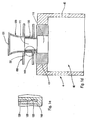
- the closure member 13 is repositionable on the conduit 120 once the material bridge 132 has been broken. Indeed, the lower part of the sleeve 130 can be engaged around the conduit 120 until the cord 133 of the sleeve 130 comes into contact with the boss 123 of the sleeve 120. An additional pressure exerted for example on the gripping flange 150 allows to pass the cord 133 below the boss 123 to achieve snap fastening. This is visible in Figure 1d, and even more clearly in Figure 1 which is an enlargement of the detail D2 of Figure 1d. The final position is reached when the lower end of the sleeve 130 abuts the plate 140. Advantageously, this latching also provides a seal between the closure member 13 and the conduit 120.
- closure member 13 can then be removed and repositioned at will.
- closure member 13 which initially serves as a filling nozzle and first-use guarantee is then conventionally used as a repositionable closure member.
- the gripping flange 150 and the plate 140 define between them a gripping space designed to receive two fingers of the user, which makes it easy to carry the dispenser constituted by the reservoir 4 and of the closure device 100.
- the closure device 200 is also made integrally by plastic injection. It also comprises a fixing member 210 internally defining an inlet passage 211, a conduit 220 defining internally an outlet passage 221 opening at a dispensing orifice 222 and a closure member 23 which cooperates with the conduit 220.
- the closure member 23 is made integrally.
- the duct 220 is provided with two gripping fins 250 which extend transversely diametrically opposite from the duct 220. Above these two fins 250, the duct 220 externally forms a detent boss 223. At its end upper, the sleeve 220 internally forms a sealing lip 224. It can even be said that this lip 224 defines the dispensing orifice 222.
- the closure member 23 comprises a sleeve 230 defining a lower end forming a ratchet cord 233 which will later cooperate with the detent boss 223 of the conduit 220.
- the sleeve 230 is connected to the conduit 220 at the cord 233 by via a material bridge 232.
- This bridge 232 may be continuous so as to extend over the entire periphery of the duct inside the sleeve. Alternatively, there may be several material bridges in the form of discrete junction points.
- the sleeve 230 extends concentrically around the upper part of the conduit 220.
- the sleeve 230 forms a sealable portion 231 which is here in the form of a ring 231 which extends radially outwards .
- the sleeve 230 forms a fixed element integral with the conduit 220 via the bridge (s) of material 232.
- the bridge (s) of material have the function of breaking or yielding so as to separate the sleeve 230 of the conduit 220.
- the closure member 23 also comprises a cover 234 which is connected to the sleeve 230 via a hinge 235.
- This hinge 235 is formed at the level of the ring 231.
- the hinge 235 thus connects the cover 234 to the hinge 233. 231.
- the cover 234 forms a sealing disk 236 intended to come into contiguous contact over the entire periphery of the ring 231. This is possible, since the disk 236 is hinged relative to the ring 231 at the level of the ring 231. articulation 235. Therefore, the cover 234 can pivot relative to the sleeve 230 so as to come down on the disc 236 on the ring 231, this is shown in Figure 2b.
- the cover 234 preferably forms a skirt 237 intended to be housed inside the sleeve 230.
- the skirt 237 may, for example, be received in force inside the sleeve 230. It is also possible to provide definitive and releasable fixing means so that the cover 234 can no longer be removed from the sleeve 230 once the cover 234 has been folded over. the sleeve 230.
- the skirt 237 may for example be provided with a harpooning profile intended to bite into the inner wall of the sleeve 230. It is also possible to provide latching means at this level.
- Fixing the cover 234 on the sleeve 230 advantageously provides a peripheral seal so that the product can not leak between the ring 231 and the disc 236.
- the cover 234 is welded to the sleeve 230 at the of the ring gear 231 and the disk 236. It is easily understood, with reference to FIG. 2b, that a peripheral weld can be produced at the contiguous edges of the ring gear 231 and the disk 236. However, the watertightness can only be achieved 234.
- the cover 234 also forms a closure sleeve 238 intended to be housed in a sealed manner inside the conduit 220 at the sealing lip 224. More specifically, the sealing lip 224 is deformed slightly against the outer wall of the sleeve 238 as can be seen in Figure 2b. Thus, the fluid can not leak out of the outlet passage 221, closed by the sleeve 238.
- the closure member forms a sealable portion which is constituted by the ring 231 and the cover 234.
- the outlet passage 221 is open towards the outside and it is thus possible to fill a reservoir connected to the fastener 210.
- the cover can be folded down as previously described. It can even be soldered.
- the user wants to use the dispenser equipped with the closure device 200, he can enter the reservoir, the conduit 220 or the fins 250 with one hand and the closure member 23 with the other hand. Rotation or traction makes it possible to break the bridge (s) of material 232.
- the closure member can then be withdrawn from the conduit 220. A distribution of fluid product is then possible through the conduit 220.
- closure 23 is also repositionable: indeed, it is possible to engage the sleeve 230 around the conduit 220 until the cord 233 engages below the boss 223. This is shown in Figure 2d. The sealing sleeve 238 is then fully engaged in the lip 224.
- the closure member fulfills a sealable filling tip function, a first-use guarantee function and a conventional repositionable cap function, while being made in one-piece fashion.
- the welding is even optional.
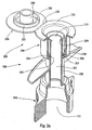
- the closure device 300 in this second embodiment of the invention has a structure and operation comparable to that of the first embodiment 200.
- the closure device 300 also comprises a fixing member 310 forming a fixing appendix 312 to the interior of which extends an inlet passage 311.
- a distribution duct 320 extends above the fixing member 310.
- the duct 320 forms an outlet passage 321 in the extension of the entrance passage 311.
- the outlet passage 321 forms a dispensing orifice 322.
- the external wall of the duct 320 also forms a continuous peripheral boss 323.
- this boss 323 can also be in the form of several distributed bosses. in a regular manner around the periphery of the conduit 320.
- the closure device 300 also comprises a closure member 33 which, although of a different shape from that of the second d embodiment, integrates functionally identical elements.
- the closure member 33 comprises a sleeve 330 which extends substantially concentrically around the conduit 320.
- the lower end of the sleeve 330 forms a ratchet cord 333 at which the sleeve 330 is connected to the conduit 320 through four discrete material bridges 332.
- the sleeve 330 forms a sealing ring 331.
- the sleeve 330 is connected to a cover 334 via a hinge 335 hinge
- the cover 334 forms a sealing edge 336 intended to come into contiguous contact with the sealing ring 331 of the sleeve 330.
- the cover 334 also forms a closure sleeve 338 intended to come into contact sealed with the outside of the upper end of the sleeve 320, as visible in Figure 3b.
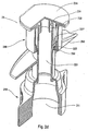
- the cover 334 When the reservoir is filled, the cover 334 can be folded down on the sleeve 330 by pivoting around the articulation hinge 335. The edge 336 then comes into contiguous contact with the ring 331. To achieve a guaranteed seal, a peripheral weld can be carried out at the joined contact between the ring 331 and the edge 336. The sleeve 330 and the cover 334 then form more than one unitary element unbreakable monobloc.
- the closing member 33 is also provided with two gripping wings 350 which extend diametrically opposite. By grasping the closure member 33 by its fins 350 and applying traction or preferably a rotation, the four material bridges 332 break so that the closure member 33 is detached from the conduit 320. The closure can be removed to disengage the dispensing orifice 322 to allow dispensing of fluid.
- the closure member 33 is repositionable on the conduit 320. To ensure a fastening of the closure member on the conduit, it is sufficient to engage the closure member on the led until the cord 333 of the sleeve 330 is housed below the boss 323 of the conduit 320. The seal is guaranteed at the top by the bushing 338 which comes into sealing contact with the upper end of the conduit 320 .
- a first characteristic lies in the fact that the closing member 23, 33 is initially connected to the outlet duct 220, 320 by one or more brittle material deck (s) 232, 332.
- a second characteristic lies in the that the closing member 23, 33 comprises a sealable portion 231, 331 which allows to close the communication between the conduit 220, 320 and the outside.
- the closure member comprises a deformable portion 235, 335.
- the closure member is repositionable and held in place by a snap.
Landscapes
- Engineering & Computer Science (AREA)
- Mechanical Engineering (AREA)
- Closures For Containers (AREA)
- Injection Moulding Of Plastics Or The Like (AREA)
- Moulds For Moulding Plastics Or The Like (AREA)
- Electrical Discharge Machining, Electrochemical Machining, And Combined Machining (AREA)
- Basic Packing Technique (AREA)
- Tubes (AREA)
- Nozzles (AREA)
Claims (10)
- Verschlussvorrichtung (200; 300) zur Anbringung auf einer Öffnung (41) eines Fluidprodukt-Vorratsbehälters (4), wobei die Vorrichtung einstückig durch Spritzen/Formen von Kunststoffmaterial verwirklicht ist und aufweist:- ein Befestigungsorgan (210; 310) zur Zusammenwirkung mit der Öffnung des Vorratsbehälters zur Verwirklichung einer dichten Festlegung,- eine Abgabeleitung (220; 320), die einen Auslassdurchlass (221; 321) für das Fluidprodukt bildet, welches in dem Vorratsbehälter enthalten ist, wobei die Leitung eine Abgabeöffnung (222; 322) bildet,- ein Verschlussorgan (23; 33) zum dichten Verschließen der Leitung, wobei das Verschlussorgan mit der Abgabeleitung (220; 320) mittels zumindest einer Materialbrücke (232; 332) verbunden ist, welche dazu bestimmt ist, beim ersten Rückziehen des Verschlussorgans zu zerbrechen, dadurch gekennzeichnet dass das Verschlussorgan (23; 33) ein versiegelbares Teil (231; 234; 331; 334) aufweist, wobei das versiegelbare Teil vor dem Versiegeln die Abgabeöffnung freilässt und nach dem Versiegeln die Abgabeöffnung (222; 322) dicht verschließt, und dass das versiegelbare Teil ein feststehendes Element (231; 331) aufweist, welches mit der Leitung mit der zumindest einen Materialbrücke verbunden ist, und eine Versiegelhaube (234; 334), die dazu bestimmt ist, auf dem feststehenden Element nicht demontierbar fest angebracht zu werden, wobei die Haube die Abgabeöffnung dicht verschließt.
- Verschlussvorrichtung nach Anspruch 1, wobei das versiegelbare Teil in Bezug auf sich selbst verformbar und verschweißbar ist.
- Verschlussvorrichtung nach einem der vorangehenden Ansprüche, wobei die Haube mit dem feststehenden Element gelenkig, vorteilhafterweise einstückig gebildet ist.
- Verschlussvorrichtung nach einem der vorangehenden Ansprüche, wobei die Haube auf das feststehende Element geschweißt ist.
- Verschlussvorrichtung nach einem der vorangehenden Ansprüche, wobei die Haube eine Dichtungshülse (238, 338) bildet, die dazu bestimmt ist, in dichtem Kontakt mit der Leitung (220, 320) zum dichten Verschließen derselben bestimmt ist.
- Verschlussvorrichtung nach einem der vorangehenden Ansprüche, wobei die Materialbrücke (232; 332) sich kontinuierlich um die Leitung (220; 320) erstreckt und außerdem eine dichte Verbindungsstelle zwischen der Leitung (220; 320) und dem Verschlussorgan (23; 33) bildet.
- Verschlussvorrichtung nach einem der vorangehenden Ansprüche, wobei das Verschlussorgan (23, 33) eine Außenmuffe aufweist, die durch ein Ende mit dem Ende der Leitung über die zumindest eine Materialbrücke verbunden ist, wobei die Muffe ein gegenüberliegendes Außenende aufweist, welches das versiegelbare Teil bildet.
- Verschlussvorrichtung nach einem der vorangehenden Ansprüche, wobei die Leitungen und das Verschlussorgan mit Rastmitteln (223; 233; 323; 333) versehen sind, die dazu bestimmt sind, nach dem Zerbrechen mit der zumindest einen Materialbrücke zusammenzuwirken.
- Verschlussvorrichtung nach Anspruch 8, wobei die Rastmittel (223; 233; 323; 333) Dichtungsmittel zum Verschließen der Leitung bilden.
- Verschlussvorrichtung nach einem der vorangehenden Ansprüche, wobei das Festlegungsorgan einen Festlegungsfortsatz (210; 310) aufweist, auf welchem die Öffnung (41) einer nachgiebigen Tasche, vorteilhafterweise durch Verschweißung festlegbar ist.
Applications Claiming Priority (3)
| Application Number | Priority Date | Filing Date | Title |
|---|---|---|---|
| FR0303144A FR2852295B1 (fr) | 2003-03-14 | 2003-03-14 | Dispositif de fermeture de reservoir de produit fluide |
| FR0303144 | 2003-03-14 | ||
| PCT/FR2004/000581 WO2004083044A2 (fr) | 2003-03-14 | 2004-03-11 | Dispositif de fermeture de reservoir de produit fluide |
Publications (2)
| Publication Number | Publication Date |
|---|---|
| EP1606190A2 EP1606190A2 (de) | 2005-12-21 |
| EP1606190B1 true EP1606190B1 (de) | 2007-05-16 |
Family
ID=32893291
Family Applications (1)
| Application Number | Title | Priority Date | Filing Date |
|---|---|---|---|
| EP04719489A Expired - Lifetime EP1606190B1 (de) | 2003-03-14 | 2004-03-11 | Verschlussvorrichtung für einen behälter für fliessfähige materialien |
Country Status (9)
| Country | Link |
|---|---|
| US (1) | US7762414B2 (de) |
| EP (1) | EP1606190B1 (de) |
| CN (1) | CN1777548A (de) |
| AT (1) | ATE362452T1 (de) |
| BR (1) | BRPI0408364A (de) |
| DE (1) | DE602004006502T2 (de) |
| ES (1) | ES2290683T3 (de) |
| FR (1) | FR2852295B1 (de) |
| WO (1) | WO2004083044A2 (de) |
Families Citing this family (27)
| Publication number | Priority date | Publication date | Assignee | Title |
|---|---|---|---|---|
| US6243691B1 (en) * | 1996-03-29 | 2001-06-05 | Onsale, Inc. | Method and system for processing and transmitting electronic auction information |
| FR2885601B1 (fr) * | 2005-05-13 | 2010-02-19 | Seaquist General Plastics | Piece de fermeture pour contenant en materiau de genre pelliculaire. |
| JP4919669B2 (ja) * | 2006-01-31 | 2012-04-18 | 日本クラウンコルク株式会社 | ヒンジキャップ付スパウトを有するパウチ |
| EP1980498A1 (de) * | 2007-04-12 | 2008-10-15 | Rexam Home and Personal Care | Einteiliger Ausguss mit einem an einer Röhre angebrachten Deckel mit abbrechbarem Materialstreifen |
| FR2933675B1 (fr) * | 2008-07-08 | 2010-08-13 | Seaquist General Plastics | Element de fermeture d'un recipient en particulier fait dans un materiau de type feuille |
| GB2470212A (en) * | 2009-05-14 | 2010-11-17 | Coda Plastics Ltd | Pouch dispensing device with dosing means |
| US9957148B2 (en) * | 2009-09-14 | 2018-05-01 | Pouch Pac Innovations, Llc | Pouch with a tube spout fitment |
| IT1399522B1 (it) * | 2010-03-30 | 2013-04-19 | Safta Spa | Contenitore richiudibile |
| USD646563S1 (en) | 2010-09-17 | 2011-10-11 | Earthbound Farm Holdings | Tamper evident container |
| US8944270B2 (en) | 2010-09-17 | 2015-02-03 | Natural Selection Foods, Llc | Container with improved tamper evident structure |
| FR2977872B1 (fr) * | 2011-07-13 | 2014-09-05 | Valois Sas | Organe de bouchage et distributeur comprenant un tel organe. |
| CN102717964A (zh) * | 2012-06-13 | 2012-10-10 | 慈溪市美德工贸有限公司 | 一种密封储运水袋 |
| JP6053462B2 (ja) * | 2012-11-09 | 2016-12-27 | 日本クロージャー株式会社 | 折り取りスパウト、スパウト付きパウチおよびその製造方法 |
| US9334097B2 (en) | 2013-03-15 | 2016-05-10 | Westrock Slatersville, Llc | Dispensing closure |
| US20140312078A1 (en) * | 2013-04-19 | 2014-10-23 | Perimeter Brand Packaging, Llc | Closure for Flexible Film Pouch |
| NL2015473B1 (en) | 2015-09-21 | 2017-04-19 | Scholle Ipn Ip Bv | A spouted pouch adapted to be filled with a flowable product. |
| US9751677B2 (en) * | 2015-09-21 | 2017-09-05 | Scholle Ipn Corporation | Pouch assembly having a plug |
| EP3681817A4 (de) * | 2017-09-11 | 2022-01-26 | Liqui-Box Corporation | Aseptische schraubkappenanordnung |
| CN108461688A (zh) * | 2018-03-20 | 2018-08-28 | 安徽天康(集团)股份有限公司 | 软包钛酸锂电池自动排气阀 |
| US11053054B2 (en) | 2018-08-03 | 2021-07-06 | Gateway Plastics, Inc. | Spout fitment and cap |
| US10442582B1 (en) | 2018-08-14 | 2019-10-15 | Phoenix Closures, Inc. | Spout fitment apparatus for a flexible container |
| IT201900006687A1 (it) | 2019-05-09 | 2020-11-09 | Guala Pack Spa | Cannuccia per imballi flessibili a pareti sottili |
| US11377267B2 (en) | 2019-05-15 | 2022-07-05 | Phoenix Closures, Inc. | Choke-resistant closure |
| DE102021113115A1 (de) | 2021-05-20 | 2022-11-24 | Georg Menshen Gmbh & Co. Kg | Ausgießer für Folienbeutel |
| EP4741310A2 (de) * | 2021-06-04 | 2026-05-13 | Hovina Inc. | Flüssigkeitsübertragungseinsatz, flüssigkeitsausgabevorrichtung und zugehörige verfahren |
| US11999519B2 (en) | 2022-08-04 | 2024-06-04 | Scholle Ipn Corporation | Filler assembly and method of filling a pouch |
| FR3150508B1 (fr) | 2023-06-27 | 2025-06-13 | Soc Lorraine De Capsules Metalliques Manufacture De Bouchage | Système de bouchage pour poche souple destiné à rester totalement attaché à la poche souple. |
Family Cites Families (8)
| Publication number | Priority date | Publication date | Assignee | Title |
|---|---|---|---|---|
| GB1054992A (de) * | 1963-01-11 | |||
| US4408700A (en) * | 1981-05-28 | 1983-10-11 | Owens-Illinois, Inc. | Multi-part dispensing closure having a frangible connecting web |
| US5104008A (en) * | 1990-12-03 | 1992-04-14 | Northern Engineering And Plastics Corp. | Resealable bottle cap with push-pull closure |
| AU6137596A (en) * | 1995-06-26 | 1997-01-30 | Taisho Pharmaceutical Co., Ltd. | Container for liquid preparations |
| US5911340A (en) * | 1995-09-14 | 1999-06-15 | Dai Nippon Printing Co., Ltd. | Spout assembly, spout assembly manufacturing apparatus and package with spout assembly |
| US6192569B1 (en) * | 1996-04-22 | 2001-02-27 | Cebal Sa | Process for manufacture of a top for a container with a detachable cover reusable as a cap |
| ES2217228T5 (es) * | 1999-05-04 | 2007-12-01 | Astepo Srl | Bolsa de envasado para un envasado libre de germenes de productos fluidos o a granel. |
| US6644487B2 (en) * | 2001-08-17 | 2003-11-11 | Seaquist Closures Foreign, Inc. | Tamper-evident closure with break-off piece retention |
-
2003
- 2003-03-14 FR FR0303144A patent/FR2852295B1/fr not_active Expired - Fee Related
-
2004
- 2004-03-11 EP EP04719489A patent/EP1606190B1/de not_active Expired - Lifetime
- 2004-03-11 DE DE602004006502T patent/DE602004006502T2/de not_active Expired - Lifetime
- 2004-03-11 WO PCT/FR2004/000581 patent/WO2004083044A2/fr not_active Ceased
- 2004-03-11 CN CNA2004800104448A patent/CN1777548A/zh active Pending
- 2004-03-11 BR BRPI0408364-4A patent/BRPI0408364A/pt not_active Application Discontinuation
- 2004-03-11 US US10/549,501 patent/US7762414B2/en not_active Expired - Fee Related
- 2004-03-11 ES ES04719489T patent/ES2290683T3/es not_active Expired - Lifetime
- 2004-03-11 AT AT04719489T patent/ATE362452T1/de not_active IP Right Cessation
Also Published As
| Publication number | Publication date |
|---|---|
| CN1777548A (zh) | 2006-05-24 |
| ATE362452T1 (de) | 2007-06-15 |
| WO2004083044A3 (fr) | 2004-10-28 |
| EP1606190A2 (de) | 2005-12-21 |
| FR2852295B1 (fr) | 2007-06-22 |
| DE602004006502D1 (de) | 2007-06-28 |
| FR2852295A1 (fr) | 2004-09-17 |
| DE602004006502T2 (de) | 2008-01-17 |
| BRPI0408364A (pt) | 2006-03-21 |
| ES2290683T3 (es) | 2008-02-16 |
| US7762414B2 (en) | 2010-07-27 |
| WO2004083044A2 (fr) | 2004-09-30 |
| US20070012644A1 (en) | 2007-01-18 |
Similar Documents
| Publication | Publication Date | Title |
|---|---|---|
| EP1606190A2 (de) | Verschlussvorrichtung für einen behälter für fliessfähige materialien | |
| EP2374727B9 (de) | Lebensmittelverpackung mit Deckel, und Verschlusssystem für eine Verpackung | |
| EP3999245B1 (de) | Vorrichtung zum verschliessen eines behälters eines flüssigen bis pastösen produkts und mit einer solchen vorrichtung verschlossene nachfüllpackung | |
| EP0268538A1 (de) | Verschluss für einen anfänglich mit einer durchstechbaren Membran verschlossenen Behälter | |
| EP1015335A1 (de) | Mehrkammer ausgabebehälter zum getrennten lagern zweier komponenten und zum unmittelbaren vermischen beim ersten gebrauch | |
| WO1996030273A1 (fr) | Distributeur pour le soutirage d'un produit fluide contenu dans un recipient | |
| EP0114007A1 (de) | Behälter zur tröpfelnden Abgabe einer bestimmten Menge von Flüssigkeit | |
| EP0786419A1 (de) | Flasche mit Dosiervorrichtung | |
| EP1190962A1 (de) | Spendertopf für zähflüssige Materialien | |
| EP2125535B1 (de) | Phiole zur aufnahme einer vordefinierten flüssigkeitsdosis | |
| EP1751023B1 (de) | Verteilvorrichtung für parfum | |
| EP2092985B1 (de) | Behälter mit Steigrohr | |
| CH629149A5 (fr) | Dispositif d'obturation et de distribution pour un recipient muni d'un goulot. | |
| FR2729924A1 (fr) | Flacon de distribution de produit | |
| EP1257475A1 (de) | Geformte rohrförmige kartusche mit kontrollierter abbrechbarer öffnung | |
| EP2364928B1 (de) | Dosierbehälter | |
| EP0147346B1 (de) | Sack aus biegsamem Kunststoff mit steifem abnehmbarem Element geeignet als Verschlusselement | |
| EP0559881B1 (de) | Verfahren zum Gewährleisten der Rotationsorientierung eines Verschlusses gegenüber einer mit einer Bezeichnung versehenen flexiblen Tube. | |
| EP1583702A1 (de) | Verschlussvorrichtung für eine behälteröffnung | |
| EP0794129A1 (de) | Verschlussvorrichtung für einen Behälter,insbesondere für ein medizinisches Fläschchen | |
| EP1284905B1 (de) | Flüssigkeitsbehälter mit scharnierverschluss | |
| FR2771386A1 (fr) | Dispositif d'obturation d'un flacon equipe d'un moyen empechant son ouverture intempestive en cas de choc | |
| EP2146923B1 (de) | Verschlussdeckel für einen behälter zur aufbewahrung von kohlensäurehaltigen flüssigkeiten und behälter mit derartigem verschluss | |
| EP4686670A1 (de) | Verschlussvorrichtung zum verschliessen des halses eines behälters oder eines behälters | |
| FR2925466A1 (fr) | Emballage refermable avec dispositif de verrouillage du systeme de fermeture |
Legal Events
| Date | Code | Title | Description |
|---|---|---|---|
| PUAI | Public reference made under article 153(3) epc to a published international application that has entered the european phase |
Free format text: ORIGINAL CODE: 0009012 |
|
| 17P | Request for examination filed |
Effective date: 20051013 |
|
| AK | Designated contracting states |
Kind code of ref document: A2 Designated state(s): AT BE BG CH CY CZ DE DK EE ES FI FR GB GR HU IE IT LI LU MC NL PL PT RO SE SI SK TR |
|
| AX | Request for extension of the european patent |
Extension state: AL LT LV MK |
|
| RIN1 | Information on inventor provided before grant (corrected) |
Inventor name: UYTTERHAEGHE, LUC Inventor name: PHILBOIS, JEAN-MARC Inventor name: BERTHELIN, FREDERIC |
|
| DAX | Request for extension of the european patent (deleted) | ||
| GRAP | Despatch of communication of intention to grant a patent |
Free format text: ORIGINAL CODE: EPIDOSNIGR1 |
|
| GRAS | Grant fee paid |
Free format text: ORIGINAL CODE: EPIDOSNIGR3 |
|
| RAP1 | Party data changed (applicant data changed or rights of an application transferred) |
Owner name: SEAQUIST GENERAL PLASTICS SAS |
|
| GRAA | (expected) grant |
Free format text: ORIGINAL CODE: 0009210 |
|
| AK | Designated contracting states |
Kind code of ref document: B1 Designated state(s): AT BE BG CH CY CZ DE DK EE ES FI FR GB GR HU IE IT LI LU MC NL PL PT RO SE SI SK TR |
|
| PG25 | Lapsed in a contracting state [announced via postgrant information from national office to epo] |
Ref country code: FI Free format text: LAPSE BECAUSE OF FAILURE TO SUBMIT A TRANSLATION OF THE DESCRIPTION OR TO PAY THE FEE WITHIN THE PRESCRIBED TIME-LIMIT Effective date: 20070516 |
|
| REG | Reference to a national code |
Ref country code: GB Ref legal event code: FG4D Free format text: NOT ENGLISH |
|
| REG | Reference to a national code |
Ref country code: CH Ref legal event code: EP |
|
| REG | Reference to a national code |
Ref country code: IE Ref legal event code: FG4D Free format text: LANGUAGE OF EP DOCUMENT: FRENCH |
|
| REF | Corresponds to: |
Ref document number: 602004006502 Country of ref document: DE Date of ref document: 20070628 Kind code of ref document: P |
|
| GBT | Gb: translation of ep patent filed (gb section 77(6)(a)/1977) |
Effective date: 20070627 |
|
| PG25 | Lapsed in a contracting state [announced via postgrant information from national office to epo] |
Ref country code: SE Free format text: LAPSE BECAUSE OF FAILURE TO SUBMIT A TRANSLATION OF THE DESCRIPTION OR TO PAY THE FEE WITHIN THE PRESCRIBED TIME-LIMIT Effective date: 20070816 |
|
| PG25 | Lapsed in a contracting state [announced via postgrant information from national office to epo] |
Ref country code: ES Free format text: LAPSE BECAUSE OF FAILURE TO SUBMIT A TRANSLATION OF THE DESCRIPTION OR TO PAY THE FEE WITHIN THE PRESCRIBED TIME-LIMIT Effective date: 20070827 |
|
| NLV1 | Nl: lapsed or annulled due to failure to fulfill the requirements of art. 29p and 29m of the patents act | ||
| PG25 | Lapsed in a contracting state [announced via postgrant information from national office to epo] |
Ref country code: PL Free format text: LAPSE BECAUSE OF FAILURE TO SUBMIT A TRANSLATION OF THE DESCRIPTION OR TO PAY THE FEE WITHIN THE PRESCRIBED TIME-LIMIT Effective date: 20070516 Ref country code: AT Free format text: LAPSE BECAUSE OF FAILURE TO SUBMIT A TRANSLATION OF THE DESCRIPTION OR TO PAY THE FEE WITHIN THE PRESCRIBED TIME-LIMIT Effective date: 20070516 |
|
| REG | Reference to a national code |
Ref country code: IE Ref legal event code: FD4D |
|
| PG25 | Lapsed in a contracting state [announced via postgrant information from national office to epo] |
Ref country code: NL Free format text: LAPSE BECAUSE OF FAILURE TO SUBMIT A TRANSLATION OF THE DESCRIPTION OR TO PAY THE FEE WITHIN THE PRESCRIBED TIME-LIMIT Effective date: 20070516 Ref country code: BG Free format text: LAPSE BECAUSE OF FAILURE TO SUBMIT A TRANSLATION OF THE DESCRIPTION OR TO PAY THE FEE WITHIN THE PRESCRIBED TIME-LIMIT Effective date: 20070816 Ref country code: IE Free format text: LAPSE BECAUSE OF FAILURE TO SUBMIT A TRANSLATION OF THE DESCRIPTION OR TO PAY THE FEE WITHIN THE PRESCRIBED TIME-LIMIT Effective date: 20070516 Ref country code: PT Free format text: LAPSE BECAUSE OF FAILURE TO SUBMIT A TRANSLATION OF THE DESCRIPTION OR TO PAY THE FEE WITHIN THE PRESCRIBED TIME-LIMIT Effective date: 20071016 Ref country code: CZ Free format text: LAPSE BECAUSE OF FAILURE TO SUBMIT A TRANSLATION OF THE DESCRIPTION OR TO PAY THE FEE WITHIN THE PRESCRIBED TIME-LIMIT Effective date: 20070516 Ref country code: SI Free format text: LAPSE BECAUSE OF FAILURE TO SUBMIT A TRANSLATION OF THE DESCRIPTION OR TO PAY THE FEE WITHIN THE PRESCRIBED TIME-LIMIT Effective date: 20070516 Ref country code: DK Free format text: LAPSE BECAUSE OF FAILURE TO SUBMIT A TRANSLATION OF THE DESCRIPTION OR TO PAY THE FEE WITHIN THE PRESCRIBED TIME-LIMIT Effective date: 20070516 |
|
| REG | Reference to a national code |
Ref country code: ES Ref legal event code: FG2A Ref document number: 2290683 Country of ref document: ES Kind code of ref document: T3 |
|
| PG25 | Lapsed in a contracting state [announced via postgrant information from national office to epo] |
Ref country code: SK Free format text: LAPSE BECAUSE OF FAILURE TO SUBMIT A TRANSLATION OF THE DESCRIPTION OR TO PAY THE FEE WITHIN THE PRESCRIBED TIME-LIMIT Effective date: 20070516 |
|
| PLBE | No opposition filed within time limit |
Free format text: ORIGINAL CODE: 0009261 |
|
| STAA | Information on the status of an ep patent application or granted ep patent |
Free format text: STATUS: NO OPPOSITION FILED WITHIN TIME LIMIT |
|
| 26N | No opposition filed |
Effective date: 20080219 |
|
| PG25 | Lapsed in a contracting state [announced via postgrant information from national office to epo] |
Ref country code: GR Free format text: LAPSE BECAUSE OF FAILURE TO SUBMIT A TRANSLATION OF THE DESCRIPTION OR TO PAY THE FEE WITHIN THE PRESCRIBED TIME-LIMIT Effective date: 20070817 |
|
| PG25 | Lapsed in a contracting state [announced via postgrant information from national office to epo] |
Ref country code: RO Free format text: LAPSE BECAUSE OF FAILURE TO SUBMIT A TRANSLATION OF THE DESCRIPTION OR TO PAY THE FEE WITHIN THE PRESCRIBED TIME-LIMIT Effective date: 20070516 |
|
| BERE | Be: lapsed |
Owner name: SEAQUIST GENERAL PLASTICS SAS Effective date: 20080331 |
|
| PG25 | Lapsed in a contracting state [announced via postgrant information from national office to epo] |
Ref country code: MC Free format text: LAPSE BECAUSE OF NON-PAYMENT OF DUE FEES Effective date: 20080331 |
|
| REG | Reference to a national code |
Ref country code: CH Ref legal event code: PL |
|
| PG25 | Lapsed in a contracting state [announced via postgrant information from national office to epo] |
Ref country code: LI Free format text: LAPSE BECAUSE OF NON-PAYMENT OF DUE FEES Effective date: 20080331 Ref country code: EE Free format text: LAPSE BECAUSE OF FAILURE TO SUBMIT A TRANSLATION OF THE DESCRIPTION OR TO PAY THE FEE WITHIN THE PRESCRIBED TIME-LIMIT Effective date: 20070516 Ref country code: CH Free format text: LAPSE BECAUSE OF NON-PAYMENT OF DUE FEES Effective date: 20080331 |
|
| PG25 | Lapsed in a contracting state [announced via postgrant information from national office to epo] |
Ref country code: BE Free format text: LAPSE BECAUSE OF NON-PAYMENT OF DUE FEES Effective date: 20080331 |
|
| PG25 | Lapsed in a contracting state [announced via postgrant information from national office to epo] |
Ref country code: CY Free format text: LAPSE BECAUSE OF FAILURE TO SUBMIT A TRANSLATION OF THE DESCRIPTION OR TO PAY THE FEE WITHIN THE PRESCRIBED TIME-LIMIT Effective date: 20070516 |
|
| PG25 | Lapsed in a contracting state [announced via postgrant information from national office to epo] |
Ref country code: HU Free format text: LAPSE BECAUSE OF FAILURE TO SUBMIT A TRANSLATION OF THE DESCRIPTION OR TO PAY THE FEE WITHIN THE PRESCRIBED TIME-LIMIT Effective date: 20071117 Ref country code: LU Free format text: LAPSE BECAUSE OF NON-PAYMENT OF DUE FEES Effective date: 20080311 |
|
| PGFP | Annual fee paid to national office [announced via postgrant information from national office to epo] |
Ref country code: FR Payment date: 20100416 Year of fee payment: 7 |
|
| PG25 | Lapsed in a contracting state [announced via postgrant information from national office to epo] |
Ref country code: TR Free format text: LAPSE BECAUSE OF FAILURE TO SUBMIT A TRANSLATION OF THE DESCRIPTION OR TO PAY THE FEE WITHIN THE PRESCRIBED TIME-LIMIT Effective date: 20070516 |
|
| REG | Reference to a national code |
Ref country code: FR Ref legal event code: ST Effective date: 20111130 |
|
| PG25 | Lapsed in a contracting state [announced via postgrant information from national office to epo] |
Ref country code: FR Free format text: LAPSE BECAUSE OF NON-PAYMENT OF DUE FEES Effective date: 20110331 |
|
| REG | Reference to a national code |
Ref country code: DE Ref legal event code: R082 Ref document number: 602004006502 Country of ref document: DE Representative=s name: DE ANNA, PIER LUIGI, DR.-ING., DE |
|
| PGFP | Annual fee paid to national office [announced via postgrant information from national office to epo] |
Ref country code: DE Payment date: 20150311 Year of fee payment: 12 Ref country code: ES Payment date: 20150324 Year of fee payment: 12 |
|
| PGFP | Annual fee paid to national office [announced via postgrant information from national office to epo] |
Ref country code: GB Payment date: 20150316 Year of fee payment: 12 |
|
| PGFP | Annual fee paid to national office [announced via postgrant information from national office to epo] |
Ref country code: IT Payment date: 20150326 Year of fee payment: 12 |
|
| REG | Reference to a national code |
Ref country code: DE Ref legal event code: R119 Ref document number: 602004006502 Country of ref document: DE |
|
| GBPC | Gb: european patent ceased through non-payment of renewal fee |
Effective date: 20160311 |
|
| PG25 | Lapsed in a contracting state [announced via postgrant information from national office to epo] |
Ref country code: GB Free format text: LAPSE BECAUSE OF NON-PAYMENT OF DUE FEES Effective date: 20160311 Ref country code: DE Free format text: LAPSE BECAUSE OF NON-PAYMENT OF DUE FEES Effective date: 20161001 |
|
| PG25 | Lapsed in a contracting state [announced via postgrant information from national office to epo] |
Ref country code: IT Free format text: LAPSE BECAUSE OF NON-PAYMENT OF DUE FEES Effective date: 20160311 |
|
| REG | Reference to a national code |
Ref country code: ES Ref legal event code: FD2A Effective date: 20170428 |
|
| PG25 | Lapsed in a contracting state [announced via postgrant information from national office to epo] |
Ref country code: ES Free format text: LAPSE BECAUSE OF FAILURE TO SUBMIT A TRANSLATION OF THE DESCRIPTION OR TO PAY THE FEE WITHIN THE PRESCRIBED TIME-LIMIT Effective date: 20160312 |