EP1607698A2 - Circuit de refrigeration - Google Patents
Circuit de refrigeration Download PDFInfo
- Publication number
- EP1607698A2 EP1607698A2 EP05009696A EP05009696A EP1607698A2 EP 1607698 A2 EP1607698 A2 EP 1607698A2 EP 05009696 A EP05009696 A EP 05009696A EP 05009696 A EP05009696 A EP 05009696A EP 1607698 A2 EP1607698 A2 EP 1607698A2
- Authority
- EP
- European Patent Office
- Prior art keywords
- refrigerant
- compressor
- accumulator
- valve
- tank
- Prior art date
- Legal status (The legal status is an assumption and is not a legal conclusion. Google has not performed a legal analysis and makes no representation as to the accuracy of the status listed.)
- Withdrawn
Links
Images



Classifications
-
- F—MECHANICAL ENGINEERING; LIGHTING; HEATING; WEAPONS; BLASTING
- F25—REFRIGERATION OR COOLING; COMBINED HEATING AND REFRIGERATION SYSTEMS; HEAT PUMP SYSTEMS; MANUFACTURE OR STORAGE OF ICE; LIQUEFACTION SOLIDIFICATION OF GASES
- F25B—REFRIGERATION MACHINES, PLANTS OR SYSTEMS; COMBINED HEATING AND REFRIGERATION SYSTEMS; HEAT PUMP SYSTEMS
- F25B43/00—Arrangements for separating or purifying gases or liquids; Arrangements for vaporising the residuum of liquid refrigerant, e.g. by heat
- F25B43/006—Accumulators
-
- F—MECHANICAL ENGINEERING; LIGHTING; HEATING; WEAPONS; BLASTING
- F25—REFRIGERATION OR COOLING; COMBINED HEATING AND REFRIGERATION SYSTEMS; HEAT PUMP SYSTEMS; MANUFACTURE OR STORAGE OF ICE; LIQUEFACTION SOLIDIFICATION OF GASES
- F25B—REFRIGERATION MACHINES, PLANTS OR SYSTEMS; COMBINED HEATING AND REFRIGERATION SYSTEMS; HEAT PUMP SYSTEMS
- F25B41/00—Fluid-circulation arrangements
- F25B41/20—Disposition of valves, e.g. of on-off valves or flow control valves
-
- F—MECHANICAL ENGINEERING; LIGHTING; HEATING; WEAPONS; BLASTING
- F25—REFRIGERATION OR COOLING; COMBINED HEATING AND REFRIGERATION SYSTEMS; HEAT PUMP SYSTEMS; MANUFACTURE OR STORAGE OF ICE; LIQUEFACTION SOLIDIFICATION OF GASES
- F25B—REFRIGERATION MACHINES, PLANTS OR SYSTEMS; COMBINED HEATING AND REFRIGERATION SYSTEMS; HEAT PUMP SYSTEMS
- F25B2309/00—Gas cycle refrigeration machines
- F25B2309/06—Compression machines, plants or systems characterised by the refrigerant being carbon dioxide
- F25B2309/061—Compression machines, plants or systems characterised by the refrigerant being carbon dioxide with cycle highest pressure above the supercritical pressure
-
- F—MECHANICAL ENGINEERING; LIGHTING; HEATING; WEAPONS; BLASTING
- F25—REFRIGERATION OR COOLING; COMBINED HEATING AND REFRIGERATION SYSTEMS; HEAT PUMP SYSTEMS; MANUFACTURE OR STORAGE OF ICE; LIQUEFACTION SOLIDIFICATION OF GASES
- F25B—REFRIGERATION MACHINES, PLANTS OR SYSTEMS; COMBINED HEATING AND REFRIGERATION SYSTEMS; HEAT PUMP SYSTEMS
- F25B2400/00—Component parts or details not otherwise provided for in this subclass
- F25B2400/16—Receivers
-
- F—MECHANICAL ENGINEERING; LIGHTING; HEATING; WEAPONS; BLASTING
- F25—REFRIGERATION OR COOLING; COMBINED HEATING AND REFRIGERATION SYSTEMS; HEAT PUMP SYSTEMS; MANUFACTURE OR STORAGE OF ICE; LIQUEFACTION SOLIDIFICATION OF GASES
- F25B—REFRIGERATION MACHINES, PLANTS OR SYSTEMS; COMBINED HEATING AND REFRIGERATION SYSTEMS; HEAT PUMP SYSTEMS
- F25B2500/00—Problems to be solved
- F25B2500/18—Optimization, e.g. high integration of refrigeration components
-
- F—MECHANICAL ENGINEERING; LIGHTING; HEATING; WEAPONS; BLASTING
- F25—REFRIGERATION OR COOLING; COMBINED HEATING AND REFRIGERATION SYSTEMS; HEAT PUMP SYSTEMS; MANUFACTURE OR STORAGE OF ICE; LIQUEFACTION SOLIDIFICATION OF GASES
- F25B—REFRIGERATION MACHINES, PLANTS OR SYSTEMS; COMBINED HEATING AND REFRIGERATION SYSTEMS; HEAT PUMP SYSTEMS
- F25B2600/00—Control issues
- F25B2600/25—Control of valves
- F25B2600/2523—Receiver valves
-
- F—MECHANICAL ENGINEERING; LIGHTING; HEATING; WEAPONS; BLASTING
- F25—REFRIGERATION OR COOLING; COMBINED HEATING AND REFRIGERATION SYSTEMS; HEAT PUMP SYSTEMS; MANUFACTURE OR STORAGE OF ICE; LIQUEFACTION SOLIDIFICATION OF GASES
- F25B—REFRIGERATION MACHINES, PLANTS OR SYSTEMS; COMBINED HEATING AND REFRIGERATION SYSTEMS; HEAT PUMP SYSTEMS
- F25B40/00—Subcoolers, desuperheaters or superheaters
-
- F—MECHANICAL ENGINEERING; LIGHTING; HEATING; WEAPONS; BLASTING
- F25—REFRIGERATION OR COOLING; COMBINED HEATING AND REFRIGERATION SYSTEMS; HEAT PUMP SYSTEMS; MANUFACTURE OR STORAGE OF ICE; LIQUEFACTION SOLIDIFICATION OF GASES
- F25B—REFRIGERATION MACHINES, PLANTS OR SYSTEMS; COMBINED HEATING AND REFRIGERATION SYSTEMS; HEAT PUMP SYSTEMS
- F25B9/00—Compression machines, plants or systems, in which the refrigerant is air or other gas of low boiling point
- F25B9/002—Compression machines, plants or systems, in which the refrigerant is air or other gas of low boiling point characterised by the refrigerant
- F25B9/008—Compression machines, plants or systems, in which the refrigerant is air or other gas of low boiling point characterised by the refrigerant the refrigerant being carbon dioxide
Definitions
- the invention relates to a refrigeration cycle according to the preamble of claim 1, 8 and 14 particularly to a "supercritical" refrigeration cycle in which the refrigerant pressure on a high pressure side is not lower than the critical pressure of the refrigerant, and to an accumulator in claim 10.
- Fig. 4 shows a system configuration of the conventional supercritical refrigeration cycle, comprising a compressor 101, a gas cooler 102, an expansion device 103, an evaporator 104, an accumulator 105 (lower pressure liquid reservoir), and an internal heat exchanger 106 for further cooling the refrigerant cooled by the gas cooler 102 by refrigerant sent from the accumulator 105 to the compressor 101.
- the accumulator 105 separates the partially liquid and gaseous refrigerant coming from the evaporator 104 into gaseous and liquid phases, and sends out mainly the gaseous phase refrigerant to the compressor.
- Lubricating oil for the compressor 101 dissolves in the liquid phase refrigerant, and since only gaseous refrigerant returns to the compressor 101, a shortage of lubricating oil for the compressor 101 can cause compressor seizure.
- the accumulator 105 has a small hole through which liquid refrigerant permanently flows at a low flow rate.
- the accumulator 105 is connected by outlet side refrigerant piping to the compressor.
- the small hole is formed through a bottom portion of the refrigerant piping.
- the size ratio between the small hole and the passage cross-section of the refrigerant passage determines the outflow rate, i.e. the dryness of the refrigerant delivered from the accumulator 105.
- the internal heat exchanger 106 performs a heat exchange, so that the refrigerant at the inlet of the compressor 101 is in an superheated vapour status.
- the carbon dioxide refrigerant is not condensed on the high pressure side, so that to cool the refrigerant efficiently by the gas cooler 102, it is preferable to increase the temperature difference between the refrigerant and the air or the like for cooling the refrigerant.
- the temperature of the refrigerant flowing into the gas cooler 102 is raised as high as possible.
- the outlet temperature of the compressor 101 can be raised by increasing the degree of superheat at the inlet of the compressor 101.
- the high temperature may degrade the lubricating oil.
- a control valve for the variable displacement compressor or the like prevents that the discharge pressure and the outlet temperature of the compressor 101 become too high.
- the suction force of the compressor 101 is lowered accordingly, which increases the suction pressure.
- the vaporization temperature of the refrigerant passing through the evaporator 104 becomes higher to reduce the cooling power of the refrigeration cycle.
- the gaseous phase of the gas-liquid separated refrigerant is delivered from the tank to the compressor side via the internal piping. At this time, part of the liquid phase is sent into the internal piping via the valve hole and mixes with the gaseous phase. At least a part of lubricating oil contained in the liquid refrigerant then is returned to the compressor.
- the control valve adjusts the proportion of liquid refrigerant to be mixed with gaseous refrigerant to deliver an appropriate amount of lubricating oil to the compressor side. Reducing the liquid refrigerant flow rate while securing a required amount of lubricating oil increases the dryness of the refrigerant from the accumulator and increases the degree of superheat of the refrigerant introduced into the compressor by passing through the internal heat exchanger.
- valve element adjusts the temperature of refrigerant discharged from the compressor close to an upper limit of a temperature range within which the lubricating oil is not degraded and at the same time delivers liquid refrigerant into the internal piping at a flow rate set in advance to prevent seizure of the compressor, it is possible to improve the coefficient of performance of the refrigeration cycle to the maximum. This improvement is realized by increasing the refrigerant dryness, and hence it is unnecessary to lower the refrigerant discharge pressure of the compressor.
- control valve integrally formed with the accumulator adjusts the flow rate of liquid refrigerant to be mixed with gaseous refrigerant in the internal piping the degree of dryness of refrigerant delivered from the accumulator is enhanced while the required amount of lubricating oil is assured. This allows to increase the degree of superheat of refrigerant introduced into the compressor and improves the coefficient of performance of the refrigeration cycle. As there is no need to lower the compressor discharge pressure the improvement in the coefficient of performance can be realized without lowering the cooling power of the refrigeration cycle.
- the refrigeration cycle in Fig. 1 is driven by the engine of an automotive vehicle, and comprises a compressor 1 for compressing refrigerant to a supercritical region, a gas cooler 2 (external heat exchanger) for cooling refrigerant discharged from the compressor 1, an expansion device 3 for decompressing refrigerant delivered from the gas cooler 2, an evaporator 4 for evaporating refrigerant decompressed by passing through the expansion device 3, an accumulator 5 for storing refrigerant delivered from the evaporator 4 while causing gas-liquid separation of the refrigerant, an internal heat exchanger 6 for performing heat exchange between refrigerant delivered from the accumulator 5 to the compressor 1 and refrigerant delivered from the gas cooler 2 to the expansion device 3, and a computation control section 7 (control means, liquid refrigerant outflow control means) for controlling a control valve 30 (refrigerant sending means) of the accumulator 5 according to the respective operating condition of the refrigeration cycle.
- a control valve 30 refrigerant sending means
- Oil for lubrication (lubricating oil) circulates through the compressor 1. A part of the lubricating oil is delivered together with discharged high-pressure refrigerant to circulate though the refrigeration cycle.
- the expansion device 3 is an orifice (restriction passage) having a fixed passage cross-section.
- the accumulator 5 is provided with a mechanism for returning lubricating oil mixed in a liquid phase portion of the refrigerant to the compressor 1.
- refrigerant flowing from the gas cooler 2 to the evaporator 4 is cooled by refrigerant flowing from the accumulator 5 to the compressor 1.
- the refrigerant flowing from the accumulator 5 to the compressor 1 is heated by the refrigerant flowing from the gas cooler 2 to the evaporator 4. This enhances the refrigerating power.
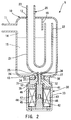
- the accumulator 5 in Fig. 2 comprises a tank 10 for storing refrigerant, a U-shaped pipe 20 (internal piping) for guiding gaseous refrigerant from the tank 10 to the compressor 1, and a control valve 30 operable to control the flow rate of the liquid refrigerant when a part of liquid refrigerant in the tank 10 flows into the U-shaped pipe 20.
- the tank 10 has an upper inlet port 11 communicating via not shown piping with the evaporator 4, and an upper hole 12 receiving one end of the U-shaped pipe 20.
- the control valve 30 is fixed to an opening 13 formed in the lower centre by fitting a valve body 31 in the opening 13.
- the tank 10 forms a gaseous phase portion 14 for storing gaseous refrigerant and a liquid phase portion 15 for storing liquid refrigerant.
- An obstruction plate 16 extends downward from an upper end wall of the tank 10 by a predetermined length.
- the U-shaped pipe 20 has a U-curved internal piping body 21.
- One end 22 opens in the gaseous phase portion 14 at an upper location in the tank 10.
- Another end 23 extends through the hole 12 and communicates with the internal heat exchanger 6.
- the one open end 22 is enclosed by the obstruction plate 16 which prevents that refrigerant in a gas-liquid mixture state from the inlet port 11 is directly drawn via the open end 22 into the U-shaped pipe 20.
- a communication valve hole 24 communicating with the liquid phase portion 15 is formed e.g. in a central lower portion of the curved section 21.
- a refrigerant passage 25 of e.g.
- the lowest flow rate is set in advance to an appropriate value based on general flow rate characteristics of refrigerant in the refrigeration cycle.
- the control valve 30 comprises a body 31 integrally formed with the tank 10, a valve element 32 inside the body 31, and a solenoid 33 for controlling movements of the valve element 32.
- the body 31 is a stepped hollow cylinder with a reduced-diameter portion 34 at an upper end, and a radially outwardly extending flange portion 35 at a lower end.
- the reduced-diameter portion 34 is fixed via an O-ring 51 in the opening 13 by a press-fit.
- a hollow cylindrical refrigerant passage-forming portion 36 protrudes coaxially with the valve element 32 from the end face of the reduced-diameter portion 34.
- the refrigerant passage-forming portion 36 is fitted in the communication hole 24 and is integrally formed with a valve seat 37 for the valve element 32.
- a portion defining the valve seat 37 and communicating with the interior of the curved section 21 defines a valve hole.
- a lateral communication hole 38 connects the interior of portion 36 with the liquid phase portion 15.
- the solenoid 33 includes a plunger 41 integrally formed with the valve element 32, a coaxial core 42 below the plunger 41, a solenoid coil 43, and a hollow cylindrical yoke 44 covering the solenoid coil 43 to form a casing of the solenoid 33.
- the solenoid coil 43 is wound on a hollow cylindrical bobbin 45.
- the core 42 is disposed in the lower half of the bobbin 45. A lower end of the core 42 is press-fitted into the lower end of the bobbin 45.
- a disk-shaped metal plate 46 is disposed between the bobbin 45 and the body 31.
- the plate 46 has a circular central opening.
- a sleeve 47 is mounted (made of a non-magnetic material), which extends from a lower end of the body 31 to an upper half of the core 42.
- An O-ring 52 seals to prevent liquid refrigerant leakage.
- the internal components of the solenoid 33 are fixed in the yoke 44, by caulking the end of the yoke 44 radially inward.
- the plunger 41 is a cylindrical body having an outer diameter slightly smaller than the inner diameter of the sleeve 47.
- a circular recessed accommodating groove in the centre of the lower end of the plunger 41 has a predetermined depth and accommodates a compression coil spring 48 which urges the plunger 41 in a direction away from the core 42.
- the elongated valve element 32 extends upwardly from the plunger 41.
- the lower end of the plunger 41 is tapered outwardly.
- the core 42 is a cylindrical body with an upper end complementary to the tapered lower end of the plunger 41.
- the magnetic circuit of the solenoid 33 is formed by the plunger 41, the core 42, the yoke 44, the plate 46, and so forth, Energization of the solenoid coil 43 is controlled by the computation control section 7.
- the valve element 32 When the solenoid coil 43 is de-energized, the valve element 32 is seated on the valve seat 37 by the compression coil spring 48. Liquid refrigerant flows from the liquid phase portion 15 into the interior of the U-shaped pipe 20 via the refrigerant passage 25 at the pre-set lowest flow rate and is mixed with gaseous refrigerant, and is delivered out of the accumulator 5.
- the lowest flow rate is set based on e.g. a minimum amount of lubricating oil required by the compressor 1.
- the horizontal axis represents enthalpy
- the vertical axis represents refrigerant pressure.
- the line from Point A to Point G corresponds to the cycle part between Point A and Point G in Fig. 1.
- the respective refrigerant states are represented by Point A at a discharge port of the compressor 1, Point B at an outlet of the gas cooler 2, Point C at an inlet of the expansion device 3, Point D at an outlet of the expansion device 3, Point E at an inlet of the accumulator 5, Point F at an outlet of the accumulator 5, and Point G at a suction port of the compressor 1.
- the operation of the refrigeration cycle is indicated by solid lines in Fig. 3, while the operation of the conventional refrigeration cycle of Fig. 4 is indicated by dotted lines as a comparative example.
- the refrigeration cycle operates along lines indicated by A - B - C - D - E - F - G in the Mollier chart.
- the refrigerant pressure is increased by the compressor 1.
- the refrigerant is discharged as high-pressure, high-temperature refrigerant (G ⁇ A) in a gaseous phase state and then is cooled by the gas cooler 2 (A ⁇ B), and is further cooled by heat exchange in the internal heat exchanger 6 (B ⁇ C).
- the cooled refrigerant then is adiabatically expanded in the expansion device 3, into low-pressure, low-temperature refrigerant in a two-phase gas-liquid state (C ⁇ D), and then is evaporated in the evaporator 4 (D ⁇ E).
- the refrigerant When the refrigerant is evaporated, it cools air in the compartment by depriving the air of latent heat of vaporization.
- carbon dioxide When carbon dioxide is used and is cooled by the gas cooler 2, the pressure does not cross the saturated vapour line, so that the refrigerant is not condensed and remains in a gaseous phase at the outlet of the gas cooler 2.
- the refrigerant When then decompressed by the expansion device 3, the refrigerant is changed in phase from the gaseous phase state to the two-phase gas-liquid state when the pressure drops below the saturated vapour line.
- the accumulator 5 carries out gas-liquid separation and delivers mainly the resulting gaseous phase refrigerant.
- part of the liquid phase refrigerant is mixed with the gaseous refrigerant, and is delivered to the compressor side (E ⁇ F).
- refrigerant in the two-phase gas-liquid state with a predetermined degree of dryness, is delivered from the accumulator 5.
- the refrigerant is heated in the internal heat exchanger 6 by heat exchange, and is controlled such that it is heated to a predetermined degree of superheat above the saturated vapour line (F ⁇ G).
- the refrigerant whose degree of superheat is controlled enters the compressor 1, where the refrigerant pressure is increased again to be changed from the state of Point G into the state of Point A.
- the degree of dryness provided by the accumulator 5 can be adjusted by controlling the valve lift of the valve portion by the control valve 30. More specifically, the position of Point F shown in the FIG. 3 Mollier chart can be moved between D and G by control of the valve lift, in order to improve the coefficient of performance of the refrigeration cycle.
- the coefficient of performance represents an efficiency indicative of an amount of work required by the compressor 1 in absorbing heat by the evaporator 4.
- the coefficient of performance is improved.
- the required cooling power can be obtained by a smaller power, which reduces load on the engine driving the automotive air conditioner, whereby an energy-saving operation of the engine can be expected.
- the valve lift of the control valve 30 is controlled by the computation control section 7 such that the position of Point F is adjusted to a side where the enthalpy is increased (right-hand side as viewed in Fig. 3), whereby the compressor discharge temperature is adjusted close to an upper limit temperature (150 °C in the present embodiment) of a range of temperatures within which the lubricating oil is not degraded.
- This adjustment is performed by detecting a temperature Td at the discharge port of the compressor 1, shown in FIG. 1. More specifically, Point F is moved rightward to increase the degree of dryness of refrigerant having passed through the accumulator 5, whereby the degree of superheat at the suction port of the compressor 1 is increased to move Point G relatively rightward (from Point G' to Point G).
- the coefficient of performance of the refrigeration cycle of the invention is further improved than in the refrigeration cycle of the comparative example, which operates along the dotted lines indicated by A'- C' - D' - G' in the Mollier chart. Further, since the improvement in the coefficient of performance is realized by the control of the degree of dryness of refrigerant delivered by the accumulator 5, that is, by a control of Point F in Fig. 3, there is no need to lower the refrigerant discharge pressure (Point A) from the compressor 1, and hence the coefficient of performance is improved without lowering the cooling power of the refrigeration cycle.
- the energization of the solenoid 33 may be turned on or off to open or close the valve portion such that the flow rate of refrigerant flowing out into the U-shaped pipe 20 is controlled (cycle or duty control).
- the control valve may be configured such that the valve portion is opened and closed e.g. by a stepping motor, or it may be configured as a so-called mechanical type control valve in which the valve element is actuated by an internal mechanical construction including springs and the pressure of refrigerant.
- the expansion device 3 instead may be configured as an expansion valve having a controllable valve mechanism.
- the control valve 30 it is also possible to configure the control valve 30 as a mechanical type control valve at reduced cost and employ a method of performing fine adjustment of a differential pressure across the valve portion by the expansion valve.
- the differential pressure of refrigerant across the valve portion to be handled by the expansion device 3 is generally in a range of 30 to 100 kgf/cm 2 under the present circumstances, the differential pressure of refrigerant to be handled by the control valve 30 is approximately 1/1000 kgf/cm 2 even when the differential pressure is calculated assuming that the water column is approximately 10 cm in height. This value is considerably small.
- the refrigeration cycle may be a supercritical refrigeration cycle using refrigerants other than carbon dioxide. It also is possible to configure the refrigeration cycle not as a supercritical refrigeration cycle but as a refrigeration cycle which uses a chlorofluorocarbon or the like as refrigerant, and in which the pressure of the refrigerant before being decompressed by the expansion device 3 is lower than the critical pressure of the refrigerant. In this case, however, since there hardly occurs a change in temperature between Point A to Point C shown in Fig. 3, it is considered that the degree of improving the coefficient of performance is smaller.
Landscapes
- Engineering & Computer Science (AREA)
- Physics & Mathematics (AREA)
- Mechanical Engineering (AREA)
- Thermal Sciences (AREA)
- General Engineering & Computer Science (AREA)
- Chemical & Material Sciences (AREA)
- Analytical Chemistry (AREA)
- Power Engineering (AREA)
- Compressor (AREA)
- Air-Conditioning For Vehicles (AREA)
Applications Claiming Priority (2)
| Application Number | Priority Date | Filing Date | Title |
|---|---|---|---|
| JP2004157260A JP2005337592A (ja) | 2004-05-27 | 2004-05-27 | 冷凍サイクル |
| JP2004157260 | 2004-05-27 |
Publications (2)
| Publication Number | Publication Date |
|---|---|
| EP1607698A2 true EP1607698A2 (fr) | 2005-12-21 |
| EP1607698A3 EP1607698A3 (fr) | 2006-10-25 |
Family
ID=34936090
Family Applications (1)
| Application Number | Title | Priority Date | Filing Date |
|---|---|---|---|
| EP05009696A Withdrawn EP1607698A3 (fr) | 2004-05-27 | 2005-05-03 | Circuit de refrigeration |
Country Status (3)
| Country | Link |
|---|---|
| US (1) | US20050262873A1 (fr) |
| EP (1) | EP1607698A3 (fr) |
| JP (1) | JP2005337592A (fr) |
Cited By (1)
| Publication number | Priority date | Publication date | Assignee | Title |
|---|---|---|---|---|
| GB2453515A (en) * | 2007-07-31 | 2009-04-15 | Space Engineering Services Ltd | Vapour compression system |
Families Citing this family (17)
| Publication number | Priority date | Publication date | Assignee | Title |
|---|---|---|---|---|
| US7685839B2 (en) * | 2004-07-09 | 2010-03-30 | Junjie Gu | Refrigeration system |
| JP2008122034A (ja) * | 2006-11-15 | 2008-05-29 | Sanden Corp | 車両用冷房装置 |
| US10184700B2 (en) * | 2009-02-09 | 2019-01-22 | Total Green Mfg. Corp. | Oil return system and method for active charge control in an air conditioning system |
| WO2013069043A1 (fr) * | 2011-11-07 | 2013-05-16 | 三菱電機株式会社 | Appareil de climatisation |
| WO2016013077A1 (fr) * | 2014-07-23 | 2016-01-28 | 三菱電機株式会社 | Dispositif à cycle de réfrigération |
| JP6482415B2 (ja) * | 2015-07-07 | 2019-03-13 | 株式会社不二工機 | アキュームレータ |
| JP6323489B2 (ja) * | 2015-08-04 | 2018-05-16 | 株式会社デンソー | ヒートポンプシステム |
| EP3338035A1 (fr) | 2015-08-19 | 2018-06-27 | Carrier Corporation | Échangeur de chaleur à gaz d'aspiration de liquide réversible |
| CN106016801B (zh) * | 2016-06-22 | 2018-11-06 | 海信容声(广东)冷柜有限公司 | 一种防低温冻油自复叠制冷系统及其控制方法 |
| DE102018120467B4 (de) | 2018-08-22 | 2022-01-20 | Hanon Systems | Vorrichtungen zum Speichern von Kältemittel eines Kältemittelkreislaufs sowie Verfahren zum Betreiben der Vorrichtungen |
| CN111207453B (zh) * | 2020-01-09 | 2021-03-23 | 珠海格力电器股份有限公司 | 空调外机、空调设备及冷冻油回收控制方法 |
| KR20230068815A (ko) | 2021-11-11 | 2023-05-18 | 현대자동차주식회사 | 차량용 통합 열관리 시스템의 냉매모듈 |
| KR20230068814A (ko) | 2021-11-11 | 2023-05-18 | 현대자동차주식회사 | 차량용 통합 열관리 시스템의 냉매모듈 |
| CN116222027B (zh) * | 2021-12-02 | 2025-08-22 | 重庆美的通用制冷设备有限公司 | 冷却组件、控制方法及装置、可读存储介质、换热机组 |
| KR20230090753A (ko) * | 2021-12-15 | 2023-06-22 | 현대자동차주식회사 | 열교환기 및 이를 포함하는 차량용 통합 열관리 시스템의 냉매모듈 |
| IT202200003557A1 (it) * | 2022-02-25 | 2023-08-25 | Onda S P A | Impianto di scambio termico. |
| US20250075955A1 (en) * | 2023-09-01 | 2025-03-06 | Rheem Manufacturing Company | Flash Tank Overflow Warning System |
Family Cites Families (13)
| Publication number | Priority date | Publication date | Assignee | Title |
|---|---|---|---|---|
| JPS633154A (ja) * | 1986-06-12 | 1988-01-08 | 株式会社デンソー | 冷凍サイクル装置 |
| IT1266773B1 (it) * | 1993-11-05 | 1997-01-21 | Franco Formenti | Dispositivo di protezione per compressori frigoriferi |
| US5746065A (en) * | 1996-08-21 | 1998-05-05 | Automotive Fluid Systems, Inc. | Accumulator deflector connection and method |
| JP3339332B2 (ja) * | 1996-11-06 | 2002-10-28 | 三菱電機株式会社 | アキュムレータ、冷凍サイクル装置 |
| EP1262348B1 (fr) * | 1997-07-31 | 2006-05-10 | Denso Corporation | Appareil à cycle frigorifique |
| JP4042220B2 (ja) * | 1997-09-24 | 2008-02-06 | 株式会社デンソー | 冷凍サイクル装置 |
| JP3365273B2 (ja) * | 1997-09-25 | 2003-01-08 | 株式会社デンソー | 冷凍サイクル |
| JPH11193967A (ja) * | 1997-12-26 | 1999-07-21 | Zexel:Kk | 冷凍サイクル |
| DE19832479A1 (de) * | 1998-07-20 | 2000-01-27 | Behr Gmbh & Co | Mit CO¶2¶ betreibbare Klimaanlage |
| JP3227651B2 (ja) * | 1998-11-18 | 2001-11-12 | 株式会社デンソー | 給湯器 |
| JP2001201213A (ja) * | 2000-01-21 | 2001-07-27 | Denso Corp | 超臨界冷凍サイクル |
| JP3812389B2 (ja) * | 2001-09-17 | 2006-08-23 | 株式会社デンソー | 冷凍サイクル装置 |
| DE10161238A1 (de) * | 2001-12-13 | 2003-06-26 | Behr Gmbh & Co | Niederdrucksammler, insbesondere für eine CO2-Klimaanlage |
-
2004
- 2004-05-27 JP JP2004157260A patent/JP2005337592A/ja active Pending
-
2005
- 2005-05-03 EP EP05009696A patent/EP1607698A3/fr not_active Withdrawn
- 2005-05-24 US US11/135,466 patent/US20050262873A1/en not_active Abandoned
Cited By (1)
| Publication number | Priority date | Publication date | Assignee | Title |
|---|---|---|---|---|
| GB2453515A (en) * | 2007-07-31 | 2009-04-15 | Space Engineering Services Ltd | Vapour compression system |
Also Published As
| Publication number | Publication date |
|---|---|
| US20050262873A1 (en) | 2005-12-01 |
| EP1607698A3 (fr) | 2006-10-25 |
| JP2005337592A (ja) | 2005-12-08 |
Similar Documents
| Publication | Publication Date | Title |
|---|---|---|
| EP1607698A2 (fr) | Circuit de refrigeration | |
| US11225125B2 (en) | Integrated valve device | |
| US9683761B2 (en) | Integration valve and heat pump cycle | |
| EP1059495B1 (fr) | Cycle de compression à vapeur surcritique | |
| US7178359B2 (en) | Ejector cycle having multiple evaporators | |
| JP4285060B2 (ja) | 蒸気圧縮式冷凍機 | |
| US11391499B2 (en) | Heat pump cycle device and valve device | |
| US10029538B2 (en) | Refrigeration cycle | |
| US20050268644A1 (en) | Vapor compression cycle having ejector | |
| JP2006125823A (ja) | エジェクタサイクル | |
| JPH11278045A (ja) | 冷凍サイクル装置 | |
| JP5544469B2 (ja) | 複合弁および車両用冷暖房装置 | |
| US6694760B2 (en) | Refrigerating cycle | |
| JP6714864B2 (ja) | 冷凍サイクル装置 | |
| JP6547698B2 (ja) | エジェクタ式冷凍サイクル | |
| JP2011202510A (ja) | 可変容量圧縮機の容量制御弁 | |
| JP2006234207A (ja) | 冷凍サイクル用減圧装置 | |
| JP2007032945A (ja) | エジェクタ式サイクルおよびその流量調節弁 | |
| JP4346538B2 (ja) | 冷凍サイクル及びアキュムレータ | |
| KR102446452B1 (ko) | 가변 용량 압축기용 제어 밸브 | |
| JP2014153016A (ja) | 冷却装置 | |
| JP2023108658A (ja) | 膨張弁、車両用冷暖房装置およびバッテリ冷却装置 | |
| JP2016014334A (ja) | 可変容量圧縮機用制御弁 | |
| JP5699263B2 (ja) | 車両用冷暖房装置に用いられる制御弁 | |
| JP7119785B2 (ja) | エジェクタ式冷凍サイクル、およびエジェクタモジュール |
Legal Events
| Date | Code | Title | Description |
|---|---|---|---|
| PUAI | Public reference made under article 153(3) epc to a published international application that has entered the european phase |
Free format text: ORIGINAL CODE: 0009012 |
|
| AK | Designated contracting states |
Kind code of ref document: A2 Designated state(s): AT BE BG CH CY CZ DE DK EE ES FI FR GB GR HU IE IS IT LI LT LU MC NL PL PT RO SE SI SK TR |
|
| AX | Request for extension of the european patent |
Extension state: AL BA HR LV MK YU |
|
| PUAL | Search report despatched |
Free format text: ORIGINAL CODE: 0009013 |
|
| AK | Designated contracting states |
Kind code of ref document: A3 Designated state(s): AT BE BG CH CY CZ DE DK EE ES FI FR GB GR HU IE IS IT LI LT LU MC NL PL PT RO SE SI SK TR |
|
| AX | Request for extension of the european patent |
Extension state: AL BA HR LV MK YU |
|
| 17P | Request for examination filed |
Effective date: 20070228 |
|
| AKX | Designation fees paid |
Designated state(s): DE FR |
|
| 17Q | First examination report despatched |
Effective date: 20080714 |
|
| STAA | Information on the status of an ep patent application or granted ep patent |
Free format text: STATUS: THE APPLICATION IS DEEMED TO BE WITHDRAWN |
|
| 18D | Application deemed to be withdrawn |
Effective date: 20081125 |