EP1608207A2 - Circuit pour alimenter des lampes - Google Patents
Circuit pour alimenter des lampes Download PDFInfo
- Publication number
- EP1608207A2 EP1608207A2 EP05010915A EP05010915A EP1608207A2 EP 1608207 A2 EP1608207 A2 EP 1608207A2 EP 05010915 A EP05010915 A EP 05010915A EP 05010915 A EP05010915 A EP 05010915A EP 1608207 A2 EP1608207 A2 EP 1608207A2
- Authority
- EP
- European Patent Office
- Prior art keywords
- circuit
- amplifier element
- light sources
- capacitor
- operating light
- Prior art date
- Legal status (The legal status is an assumption and is not a legal conclusion. Google has not performed a legal analysis and makes no representation as to the accuracy of the status listed.)
- Withdrawn
Links
Images


Classifications
-
- H—ELECTRICITY
- H05—ELECTRIC TECHNIQUES NOT OTHERWISE PROVIDED FOR
- H05B—ELECTRIC HEATING; ELECTRIC LIGHT SOURCES NOT OTHERWISE PROVIDED FOR; CIRCUIT ARRANGEMENTS FOR ELECTRIC LIGHT SOURCES, IN GENERAL
- H05B41/00—Circuit arrangements or apparatus for igniting or operating discharge lamps
- H05B41/14—Circuit arrangements
- H05B41/26—Circuit arrangements in which the lamp is fed by power derived from DC by means of a converter, e.g. by high-voltage DC
- H05B41/28—Circuit arrangements in which the lamp is fed by power derived from DC by means of a converter, e.g. by high-voltage DC using static converters
- H05B41/282—Circuit arrangements in which the lamp is fed by power derived from DC by means of a converter, e.g. by high-voltage DC using static converters with semiconductor devices
- H05B41/2825—Circuit arrangements in which the lamp is fed by power derived from DC by means of a converter, e.g. by high-voltage DC using static converters with semiconductor devices by means of a bridge converter in the final stage
-
- H—ELECTRICITY
- H05—ELECTRIC TECHNIQUES NOT OTHERWISE PROVIDED FOR
- H05B—ELECTRIC HEATING; ELECTRIC LIGHT SOURCES NOT OTHERWISE PROVIDED FOR; CIRCUIT ARRANGEMENTS FOR ELECTRIC LIGHT SOURCES, IN GENERAL
- H05B39/00—Circuit arrangements or apparatus for operating incandescent light sources
- H05B39/04—Controlling
- H05B39/041—Controlling the light-intensity of the source
- H05B39/044—Controlling the light-intensity of the source continuously
- H05B39/045—Controlling the light-intensity of the source continuously with high-frequency bridge converters
-
- Y—GENERAL TAGGING OF NEW TECHNOLOGICAL DEVELOPMENTS; GENERAL TAGGING OF CROSS-SECTIONAL TECHNOLOGIES SPANNING OVER SEVERAL SECTIONS OF THE IPC; TECHNICAL SUBJECTS COVERED BY FORMER USPC CROSS-REFERENCE ART COLLECTIONS [XRACs] AND DIGESTS
- Y02—TECHNOLOGIES OR APPLICATIONS FOR MITIGATION OR ADAPTATION AGAINST CLIMATE CHANGE
- Y02B—CLIMATE CHANGE MITIGATION TECHNOLOGIES RELATED TO BUILDINGS, e.g. HOUSING, HOUSE APPLIANCES OR RELATED END-USER APPLICATIONS
- Y02B20/00—Energy efficient lighting technologies, e.g. halogen lamps or gas discharge lamps
Definitions
- the invention relates to a circuit for operating light sources.
- it concerns the invention half-bridge inverter for the operation of halogen incandescent lamps.
- Half-wave inverters are well-known for operating light sources.
- the half-bridge inverter is powered by a supply voltage, the is a DC voltage.
- the DC voltage can be pulsed without the Quality of the light.
- Halogen bulbs provide such a light source
- Half-bridge inverters for halogen incandescent lamps are therefore in general of a rectified mains voltage as the supply voltage fed, with no smoothing is provided.
- half-bridge inverters for halogen incandescent lamps for cost reasons are designed as self-oscillating inverters.
- Self-oscillating in this context means that an output circuit Control signal for electronic switch of the half-bridge is removed.
- Half-bridge inverters consists essentially of the series connection an upper and a lower electronic switch operating in a half-bridge center are connected and between the supply voltage and a ground potential are switched.
- the oscillation of the half-bridge inverter must be through a start circuit to be started. This is necessary after each half-wave, because the oscillation at low instantaneous mains voltage breaks off.
- the starting circuit consists essentially from a start capacitor and a trigger element. Once the tension at the start capacitor exceeds a trigger threshold, a start pulse is triggered; This means that the trigger element is the starting capacitor to the control electrode the lower electronic switch switches. This will be the bottom electronic Switch on and the vibration of the half-bridge inverter uses.
- the starting capacitor has to deliver so much energy so that the lower electronic switch stays on safely and long enough.
- a circuit for operating light sources includes an amplifier element having an input and an output. Without the general public to restrict, it is assumed that the potentials at the entrance and at the output are related to the ground potential.
- the output of the amplifier element is connected to the starting capacitor, which is also ground-referenced. If a positive signal is present at the input of the amplifier element, the start capacitor becomes discharged.
- the high pass generates at a rising edge at the half-bridge center a positive signal at the input of the amplifier element.
- the starting capacitor is thereby according to the invention then discharged when the upper and not the lower electronic switch turns on.
- the start of the oscillation of the half-bridge inverter is explained as above, triggered by a start pulse on the lower electronic switch. At the this starting process is in the present invention, the start-capacitor Do not discharge, thereby ensuring a reliable start of the half-bridge inverter is possible.
- FIG. 1 shows an exemplary embodiment of a circuit according to the invention for the Operation of light sources shown.
- a connection for a supply voltage which is marked with a + sign, and a ground potential is the series connection of an upper electronic switch T1 and a switched lower electronic switch T2.
- the connection node M forms a half-bridge center.
- the electronic switches are called NPN bipolar transistors shown. However, there may be other electronic switches such as As MOSFET or IGBT can be used. Parallel to every electronic Switch is shown in each case an optional freewheeling diode.
- T1 and T2 Parallel to the series connection of T1 and T2 is the series connection of two coupling capacitors C11 and C12 switched. Between the connection point of C11 and C12 and the half-bridge center M are provided by the half-bridge inverter, consisting essentially of T1, T2, C11 and C12 one opposite a mains voltage high-frequency AC voltage. At this AC voltage is the series connection of the primary winding of a feedback transformer Tr and a load switched. A coupling capacitor C11 or C12 can be omitted.
- the load is represented by a resistor labeled Lp.
- Weight In the simplest case, it can only consist of one incandescent lamp. But it can also Low-voltage halogen bulbs can be connected via a transformer.
- the feedback transformer Tr detects a load current with the primary winding and couples it via two secondary windings to respective control electrodes of T1 and T2. As a result, a feedback loop is closed, creating a self-oscillating Half-bridge inverter is created.
- a start circuit is controlled by a start capacitor C3, a resistor R11 and a trigger element DIAC is formed.
- C3 and R11 are in series between the supply voltage and the ground potential switched.
- the DIAC connects the connection point from C3 and R11 to the control electrode of the lower electronic Switch T2.
- C3 is charged by the supply voltage via R11. Reached the voltage has a value that is above the threshold voltage of the DIAC of typically 33V C3 gives a start pulse to the control electrode of T2.
- the circuit contains an amplifier element V1, which is shown in FIG is based on mass.
- An output of V1 is connected to C3.
- An input from V1 According to the invention is connected via a high pass with the half-bridge center point M.
- the high pass is in the embodiment of Figure 1 by a high-pass capacitor C4 realized.
- Resistor R1 has a typical value of 330k ohms and the high pass capacitor C4 a typical value of 10nF.
- FIG. 2 shows a modified variant of the embodiment of Figure 1 is shown.
- the resistor R11 is divided into a first in Figure 2
- R2 connects the starting capacitor C3 with the half-bridge center M, while R1 the half-bridge center M connects to the supply voltage. This happens in the example via the load and the primary winding of the feedback transformer Tr.
- R1 and R2 typically has a value of 220kOhm each. Opposite the variant in Figure 1 can thus be reduced, the power loss of the resistors. moreover When the half-bridge is switched off, the starting capacitor C3 is charged slower. This causes a smaller number of start pulses per unit time, which is the component load and reduces the quiescent current consumption of the circuit.
- An acceleration capacitor C1 connects the starting capacitor C3 in FIG with the supply voltage. This will cause a faster triggering of a start pulse reached after a mains voltage zero crossing. Indicates the supply voltage a sufficiently high AC component, so the acceleration capacitor is sufficient C1 alone, to the start capacitor C3 to the threshold of the trigger element DIAC. the resistors R1 and R2 or R11 can then omitted.
- a high AC component of the supply voltage is then when a sinusoidal line voltage through a full-bridge rectifier rectified and not smoothed.
- a high alternating current component of the supply voltage is also present if the circuit is connected to a phase-angle or phase-section dimmer is operated.
- FIG. 3 shows a further exemplary embodiment of a circuit according to the invention.
- the second resistor R2 is split into the series connection of a third and a fourth resistor R3, R4. Between R3 and R4 is a first connection point N1.
- the high-pass capacitor C4 is not directly connected to the half-bridge center M but is connected to the connection point N1 and thus connected to the half-bridge center M via R4.
- R3 to R4 the characteristic of the high pass consisting of R4 and C4 can be set, regardless of the sum of the resistors R3 and R4.
- Typical values are: C1: 3.3nF; C3: 10nF; C4 22nF; R3: 75kOhms; R4: 75kOhm.
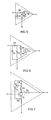
- FIG. 4 shows an exemplary embodiment of an amplifier element V1, such as FIG it finds use in the invention.
- the example in Figure 4 represents the simplest Example of V1.
- An NPN bipolar transistor T3 is connected to the emitter terminal at the ground potential.
- the base forms the input of the amplifier element, the collector forms the output of the amplifier element.
- a resistor R5 is connected, which typically has a value of 470 ohms. Lies a positive signal at the input, so the transistor T3 is driven on discharges via its collector the starting capacitor C3.
- FIG. 5 shows a further exemplary embodiment of an amplifier element V1, as used in the invention.
- the example in Figure 4 was in Figure 5 extended to the diodes D1 and D2.
- the input of the amplifier element is connected via D2 to the base of T3 and via D1 to the ground potential. In order to the switching characteristics of T3 are improved.
- FIG. 6 shows a further exemplary embodiment of an amplifier element V1, as used in the invention.
- the example in Figure 5 was in Figure 6 extended by the resistor R5 and the capacitor C5.
- R5 and C5 form a delay device.
- R5 is connected in series with D2 and C5 connects D2 with the ground potential.
- the delay device is achieved that the starting capacitor C3 is not discharged immediately when a signal at the input of the Amplifier element is present, but only when C5 was charged. This can important for the suppression of interference signals.
- FIG. 7 shows a further exemplary embodiment of an amplifier element V1, as used in the invention.
- the example in Figure 4 was in Figure 7 extended by a latching device.
- the collector of T3 is now over one Resistor R6 connected to the output of the amplifier element.
- the latching element forms the resistor R7, the capacitor C6 and the PNP transistor T4.
- the series connection of R7 and C6 is connected in parallel with the R6.
- the collector of T4 is connected to the base of T3 and the collector of T3 is via R7 with connected to the base of T4.
- the emitter of T4 is connected to the output of the amplifier element connected.
- the interconnection of T3 and T4 in the manner described is known as a thyristor replica.
- the thyristor snaps into place and turns off again when a holding current supplied by C3 is under a holding current threshold drops.
- the latching of the thyristor is delayed by C6.
- Replacing C6 with a resistor locks the thyristor without delay one.
- the Einraraxschaft the amplifier element causes the half-bridge inverter is switched off as soon as at the input of the amplifier element long enough is a positive signal. This can be used to switch off in the event of an error, e.g. Short circuit on the load, to be used. To restart, the Circuit can be disconnected from the supply voltage at short notice.
- an error e.g. Short circuit on the load
- the deceleration device from FIG. 6 can also be equipped with a latching device Figure 7 are combined.
Landscapes
- Amplifiers (AREA)
- Circuit Arrangements For Discharge Lamps (AREA)
- Circuit Arrangement For Electric Light Sources In General (AREA)
Applications Claiming Priority (2)
| Application Number | Priority Date | Filing Date | Title |
|---|---|---|---|
| DE102004028799 | 2004-06-15 | ||
| DE102004028799A DE102004028799A1 (de) | 2004-06-15 | 2004-06-15 | Schaltung zum Betrieb von Lichtquellen |
Publications (2)
| Publication Number | Publication Date |
|---|---|
| EP1608207A2 true EP1608207A2 (fr) | 2005-12-21 |
| EP1608207A3 EP1608207A3 (fr) | 2006-06-07 |
Family
ID=34936726
Family Applications (1)
| Application Number | Title | Priority Date | Filing Date |
|---|---|---|---|
| EP05010915A Withdrawn EP1608207A3 (fr) | 2004-06-15 | 2005-05-19 | Circuit pour alimenter des lampes |
Country Status (4)
| Country | Link |
|---|---|
| US (1) | US20050275353A1 (fr) |
| EP (1) | EP1608207A3 (fr) |
| CA (1) | CA2509874A1 (fr) |
| DE (1) | DE102004028799A1 (fr) |
Cited By (2)
| Publication number | Priority date | Publication date | Assignee | Title |
|---|---|---|---|---|
| EP2268108A1 (fr) * | 2009-06-22 | 2010-12-29 | Osram Gesellschaft mit Beschränkter Haftung | Convertisseur pour alimenter des sources lumineuses, méthode et support associés. |
| WO2014187724A1 (fr) * | 2013-05-24 | 2014-11-27 | Koninklijke Philips N.V. | Commande de convertisseur à non auto-excitation |
Families Citing this family (1)
| Publication number | Priority date | Publication date | Assignee | Title |
|---|---|---|---|---|
| KR20110031498A (ko) * | 2008-07-16 | 2011-03-28 | 오스람 게젤샤프트 미트 베쉬랭크터 하프퉁 | 적어도 하나의 조명 디바이스를 동작시키기 위한 회로 어레인지먼트 및 방법 |
Family Cites Families (5)
| Publication number | Priority date | Publication date | Assignee | Title |
|---|---|---|---|---|
| DE4416401A1 (de) * | 1994-05-09 | 1995-11-16 | Patent Treuhand Ges Fuer Elektrische Gluehlampen Mbh | Schaltungsanordnung zum Betreiben elektrischer Lampen |
| DE19633372A1 (de) * | 1996-08-19 | 1998-02-26 | Patent Treuhand Ges Fuer Elektrische Gluehlampen Mbh | Schaltungsanordnung zum Betreiben von elektrischen Glühlampen |
| DE19722124A1 (de) * | 1997-05-27 | 1998-12-03 | Patent Treuhand Ges Fuer Elektrische Gluehlampen Mbh | Schaltungsanordnung zum Betreiben elektrischer Glühlampen |
| DE10062047A1 (de) * | 2000-12-13 | 2002-06-20 | Patent Treuhand Ges Fuer Elektrische Gluehlampen Mbh | Elektronischer Transformator mit guter Immunität gegen Hochspannungsimpulse |
| DE10160790A1 (de) * | 2001-01-12 | 2002-08-08 | Patent Treuhand Ges Fuer Elektrische Gluehlampen Mbh | Schaltungsanordnung zum Einschalten einer Teilschaltungsanordnung |
-
2004
- 2004-06-15 DE DE102004028799A patent/DE102004028799A1/de not_active Withdrawn
-
2005
- 2005-05-19 EP EP05010915A patent/EP1608207A3/fr not_active Withdrawn
- 2005-06-08 US US11/147,210 patent/US20050275353A1/en not_active Abandoned
- 2005-06-14 CA CA002509874A patent/CA2509874A1/fr not_active Abandoned
Cited By (2)
| Publication number | Priority date | Publication date | Assignee | Title |
|---|---|---|---|---|
| EP2268108A1 (fr) * | 2009-06-22 | 2010-12-29 | Osram Gesellschaft mit Beschränkter Haftung | Convertisseur pour alimenter des sources lumineuses, méthode et support associés. |
| WO2014187724A1 (fr) * | 2013-05-24 | 2014-11-27 | Koninklijke Philips N.V. | Commande de convertisseur à non auto-excitation |
Also Published As
| Publication number | Publication date |
|---|---|
| DE102004028799A1 (de) | 2006-01-05 |
| US20050275353A1 (en) | 2005-12-15 |
| EP1608207A3 (fr) | 2006-06-07 |
| CA2509874A1 (fr) | 2005-12-15 |
Similar Documents
| Publication | Publication Date | Title |
|---|---|---|
| DE69019648T2 (de) | Gerät zur Versorgung einer Leuchtstofflampe. | |
| DE4002334C2 (de) | Schaltung zum Betreiben einer elektrischen Entladelampe in einem Kraftfahrzeug | |
| DE69208218T2 (de) | Steuerungsschaltung für eine Entladungslampe | |
| DE69604996T2 (de) | Halbbrückentreiberschaltung | |
| CH642796A5 (de) | Schaltungsanordnung fuer ein integrierbares elektronisches relais. | |
| EP0957662B1 (fr) | Circuit pour alimenter des lampes électriques | |
| WO2008055545A1 (fr) | Convertisseur cc/cc autohétérodyne et procédé à cet effet | |
| DE102009009535A1 (de) | Schaltung zur Ansteuerung eines Betriebsgeräts für eine Lichtanwendung, Betriebsgerät und Verfahren zum Betrieb der Schaltung | |
| EP0825806B1 (fr) | Circuit pour alimenter des lampes à incandescence | |
| DE4342082C2 (de) | Steuerschaltung zum Erzeugen von Schaltsignalen für Leistungstranistoren | |
| DE3813672C2 (de) | Wechselrichter für eine induktive Last | |
| DE10062047A1 (de) | Elektronischer Transformator mit guter Immunität gegen Hochspannungsimpulse | |
| EP2208400A1 (fr) | Alimentation en courant commutable pour circuits auxiliaires dans un convertisseur | |
| EP1608207A2 (fr) | Circuit pour alimenter des lampes | |
| EP1326484B1 (fr) | Appareil pour alimenter des lampes à décharge | |
| DE10206175B4 (de) | Schaltung zum Betreiben einer Entladungslampe | |
| EP1608208B1 (fr) | Circuit avec dispositif de coupure pour alimenter des sources lumineuses | |
| EP0276460B1 (fr) | Disposition de circuit pour mettre en oeuvre une lampe à décharge basse pression | |
| EP0881864B1 (fr) | Circuit pour l'alimentation des lampes incandescentes | |
| EP1753272A2 (fr) | Circuit convertisseur comprenant une inductance au lieu d' un transformateur, pour l' alimentation pulsée d' une lampe à barrière diélectrique. | |
| EP0682464A1 (fr) | Circuit pour alimenter des lampes électriques | |
| DE69618148T2 (de) | Schwingschaltung für EL Element | |
| EP0809923B1 (fr) | Circuit destine au fonctionnement d'une lampe a decharge | |
| DE4436465A1 (de) | Schaltungsanordnung zum Betreiben von Glühlampen | |
| EP0648068A1 (fr) | Circuit d'alimentation de lampes électriques |
Legal Events
| Date | Code | Title | Description |
|---|---|---|---|
| PUAI | Public reference made under article 153(3) epc to a published international application that has entered the european phase |
Free format text: ORIGINAL CODE: 0009012 |
|
| AK | Designated contracting states |
Kind code of ref document: A2 Designated state(s): AT BE BG CH CY CZ DE DK EE ES FI FR GB GR HU IE IS IT LI LT LU MC NL PL PT RO SE SI SK TR |
|
| AX | Request for extension of the european patent |
Extension state: AL BA HR LV MK YU |
|
| PUAL | Search report despatched |
Free format text: ORIGINAL CODE: 0009013 |
|
| AK | Designated contracting states |
Kind code of ref document: A3 Designated state(s): AT BE BG CH CY CZ DE DK EE ES FI FR GB GR HU IE IS IT LI LT LU MC NL PL PT RO SE SI SK TR |
|
| AX | Request for extension of the european patent |
Extension state: AL BA HR LV MK YU |
|
| 17P | Request for examination filed |
Effective date: 20060710 |
|
| 17Q | First examination report despatched |
Effective date: 20061120 |
|
| AKX | Designation fees paid |
Designated state(s): AT BE BG CH CY CZ DE DK EE ES FI FR GB GR HU IE IS IT LI LT LU MC NL PL PT RO SE SI SK TR |
|
| 17Q | First examination report despatched |
Effective date: 20061120 |
|
| STAA | Information on the status of an ep patent application or granted ep patent |
Free format text: STATUS: THE APPLICATION IS DEEMED TO BE WITHDRAWN |
|
| 18D | Application deemed to be withdrawn |
Effective date: 20071023 |