EP1609908A2 - Procédé et dispositif pour réduire des vibrations de flexion à au moins un cylindre rotatif d`une machine d`usinage et machine d`usinage - Google Patents
Procédé et dispositif pour réduire des vibrations de flexion à au moins un cylindre rotatif d`une machine d`usinage et machine d`usinage Download PDFInfo
- Publication number
- EP1609908A2 EP1609908A2 EP05107870A EP05107870A EP1609908A2 EP 1609908 A2 EP1609908 A2 EP 1609908A2 EP 05107870 A EP05107870 A EP 05107870A EP 05107870 A EP05107870 A EP 05107870A EP 1609908 A2 EP1609908 A2 EP 1609908A2
- Authority
- EP
- European Patent Office
- Prior art keywords
- cylinder
- actuator
- processing machine
- cylinders
- rotating cylinder
- Prior art date
- Legal status (The legal status is an assumption and is not a legal conclusion. Google has not performed a legal analysis and makes no representation as to the accuracy of the status listed.)
- Granted
Links
Images


Classifications
-
- B—PERFORMING OPERATIONS; TRANSPORTING
- B41—PRINTING; LINING MACHINES; TYPEWRITERS; STAMPS
- B41F—PRINTING MACHINES OR PRESSES
- B41F13/00—Common details of rotary presses or machines
- B41F13/08—Cylinders
- B41F13/085—Cylinders with means for preventing or damping vibrations or shocks
-
- D—TEXTILES; PAPER
- D21—PAPER-MAKING; PRODUCTION OF CELLULOSE
- D21G—CALENDERS; ACCESSORIES FOR PAPER-MAKING MACHINES
- D21G1/00—Calenders; Smoothing apparatus
- D21G1/0073—Accessories for calenders
- D21G1/008—Vibration-preventing or -eliminating devices
-
- F—MECHANICAL ENGINEERING; LIGHTING; HEATING; WEAPONS; BLASTING
- F16—ENGINEERING ELEMENTS AND UNITS; GENERAL MEASURES FOR PRODUCING AND MAINTAINING EFFECTIVE FUNCTIONING OF MACHINES OR INSTALLATIONS; THERMAL INSULATION IN GENERAL
- F16F—SPRINGS; SHOCK-ABSORBERS; MEANS FOR DAMPING VIBRATION
- F16F15/00—Suppression of vibrations in systems; Means or arrangements for avoiding or reducing out-of-balance forces, e.g. due to motion
- F16F15/02—Suppression of vibrations of non-rotating, e.g. reciprocating systems; Suppression of vibrations of rotating systems by use of members not moving with the rotating systems
-
- Y—GENERAL TAGGING OF NEW TECHNOLOGICAL DEVELOPMENTS; GENERAL TAGGING OF CROSS-SECTIONAL TECHNOLOGIES SPANNING OVER SEVERAL SECTIONS OF THE IPC; TECHNICAL SUBJECTS COVERED BY FORMER USPC CROSS-REFERENCE ART COLLECTIONS [XRACs] AND DIGESTS
- Y10—TECHNICAL SUBJECTS COVERED BY FORMER USPC
- Y10T—TECHNICAL SUBJECTS COVERED BY FORMER US CLASSIFICATION
- Y10T74/00—Machine element or mechanism
- Y10T74/21—Elements
- Y10T74/2121—Flywheel, motion smoothing-type
- Y10T74/2127—Flywheel, motion smoothing-type with electrical or magnetic damping
Definitions
- the invention relates to methods for reducing bending vibrations at least a rotating cylinder of a processing machine and a processing machine according to the preamble of claims 1, 5, 22, 23 and 28 respectively.
- EP 0 956 950 A1 discloses a method and a device for active Suppressing vibrations known, with balancing forces depending on the measured forces z. B. be applied to rollers.
- the frequency for the Activation of the force is constantly u. a. determined from the current speed, the Phase and amplitude from measurements of displacement signals of a distance sensor.
- EP 0 331 870 A2 discloses a device for supporting cylinders, wherein pins a cylinder arranged in two in the axial direction of the cylinder side by side Bearings are stored. By means of pressure cylinders, the bearings can be individually perpendicular to Rotation axis are moved to compensate, for example, a deflection.
- a method for compensating vibrations discloses rotating components, wherein in an actuator in the region of a lateral surface of the rotating component is arranged, and upon activation in dependence of the Angular position of the rotating component of the vibration with a force component in counteracts axial direction.
- JP 4-236819 A describes a system for reducing bending vibrations a shaft, wherein a rotating disc connected to the shaft through Piezo elements via electromagnets as a function of measured values with forces is charged.
- WO 97/03832 A1 shows various aspects in its discussion of the prior art Ways through which a deflection or a bending vibration on impression rollers static can be reduced. It proposes as a dynamic solution, occurring Measure vibrations, and these measured values for control and activation of Actuators use.
- DE 199 30 600 A1 discloses a method for reducing unwanted Bending vibrations on a rotating component of a coating device with a Actuator, wherein the actuator acts on a journal.
- DE 196 52 769 A1 discloses a method for damping unwanted Vibrations on a roll of a paper machine with one on the journal of the roller acting actuator.
- the invention is based on the object, methods for reducing Bending vibrations on at least one rotating cylinder Creating a processing machine and a processing machine.
- the correlation of the countermeasure to be taken with the rotational angle position is from particular advantage, since hereby, for example, many of the periodically recurring Disruptions, such. B. asymmetries, surface defects, channels and others Interruptions on the lateral surface, imbalance, is met.
- web-shaped Good is between two side frames 02; 03 rotatably mounted.
- the cylinder 01 z. B. each end face in bearings 04; 06 mounted pin 07; 08 on.
- the cylinder 01 has z. B. a length of 1350 to 1550 mm and a diameter from Z. B. 450 to 700, in particular from 500 to 600 mm.
- the cylinder 01 has z. B. a ratio between length L01 and diameter D01 from 6 to 12, in particular between 7 and 11 on.
- cylinder 01 To reduce the unwanted vibrations cylinder 01 is at least one Actuator 10; 11 assigned, by means of which the oscillation are counteracted can.
- the actuator 10; 11 is acted upon by signals S, whose sequence and / or their height in dependence on a rotational angle position ⁇ of the rotating Component is held.
- the angular position ⁇ of the cylinder 01 is z. B. either off a machine control, not shown, or by a, not shown, the Cylinder 01 driving angle-controlled electric motor known or it will determined by means of a sensor on the cylinder 01.
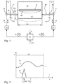
- Fig. 2 shows exemplary representations for the course and the height of z. B. in one Control or storage device 12 (or in a circuit) stored or held signals S as a function of the angular position ⁇ .
- the illustrated, and periodically repeating period can be in the presence of a single fault 09, for example, a revolution (2 ⁇ or 360 °) in the circumferential direction, or at several, symmetrically arranged, comparable interference 09 z. B. a integer part of the revolution (eg 180 °, 120 ° etc.).
- the actuator is during a stationary operating situation periodically recurring with the held Sequence or height of the signal S acted upon.
- the dependence S ( ⁇ ) can be considered discrete Impulse (a) or stored as within a period continuous function (b) be.
- an application is made with a variable force, by at least one pin 04; 06 of the rotating member 01; 18 at least once each Rotation is selectively applied with a corresponding force pulse.
- the signal S is directly correlated with the angular position ⁇ .
- various dependencies can be deposited be. For example, in the vicinity of rotational speeds of the resonance frequency of Stimulation of the cylinder 01 higher levels be required than in other areas. These dependencies can also be linked mathematically or in others Be produced manner. Thus, for nearly the same configurations, the course may equal, but the absolute height with the present angular velocity d ⁇ / dt, as Offset or spreading, be correlated.
- an actuator 10 acts in each case; 11 on each of the Pin 07; 08, by a coupling 13; 14 z. B. the pin 07; 08 via a bearing 16; 17 includes.
- the coupling 13 engages; 14 at a part of the cones, which on the side facing away from the cylinder 01 side of the bearing 04; 06 about this protrudes.
- the controller 12 is now the dashed lines shown the cylinder 01 and pin 07; 08 counteracted in the appropriate Drehwinkellagen ⁇ corresponding signals S, or continuously with a steady Course, the actuator 10; 11 a counter force (positive or negative) on the pin applies.
- the signal includes the height and, if necessary, the direction of the the actuator to be applied counterforce.
- the bearings 04; 06 provide for the pin 07; 08 a clamping point.
- About the lever arm representing part of the pin 07; 08 a bending moment is introduced into the cylinder 01.
- it can in principle be an actuator 10; 11 be sufficient for the cylinder 01, but advantageous is the arrangement of two Actuators 10; 11, each in the region of a pin 04; 06th
- the actuator 10; 11 may in particular as a piezoelectric element 10; 11 executed.
- the Signal S controls, for example, the voltage from an unillustrated Voltage source, which at the piezoelectric element 10; 11 has to lie. Instead of the signal S can be supplied to the actuator directly a corresponding voltage, which is already provided by the controller 12 in this case.
- actuators 10; 11 However, other facilities, such. B. based on magnetic force or hydraulic units in question.
- Per revolution of the cylinder 01 is or be the pin 07; 08 of the cylinder 01 targeted at least once with an external force or a force pulse or experience at least once per revolution a change in the targeted from the outside applied force.
- the control of the actuators 10; 11 is done now for example, in the o. g. Way such that in particular the suggestion of Oscillation during the passage of the disturbances 09; 19 is steamed.
- a corresponding pulse on the signal S on the pin 07; 08 are given.
- a big advantage of this procedure is that the signal S or the opposing force is maintained, and therefore at the time of the suggestion Potential vibration, the counterforce or a travel is already acted upon. It is not measured first a negative impact to a suitable reaction initiate.
- the cylinders 01; 18 are z. B. for on or off or for varying the employment in all examples preferably with respect to their axes of rotation at a distance from each other changeable stored.
- at least one of the cylinders, z. B. the cylinder 01 z. B. in the eccentric 04; 06 executed bearings 04; 06 stored. He can, however be guided pivotally on levers or in a linear guide.
- the cylinder 01 is movably mounted.
- the Actuator 10 attacks z. B. at the camp 04; 06 itself, which is either in the side frame 02; 03 movable, or for example as an eccentric (eg Four-ring bearing) is executed.
- the cylinder 01 is corresponding the signals S in a direction of movement, which substantially is perpendicular to the axis of rotation of the cylinder 01.
- the movement has at least one Component to a cooperating cylinder 18 toward or away from, on.
- the cylinder 01, z. B. as a forme cylinder 01, z. B. again with the second cylinder 18th together, which no, one or more disorders 19 on its lateral surface having.
- the control of the actuators 10; 11 takes place as already for the first Embodiment set forth.
- the signal S information about the Travel included. An excitation during the passage of the fault and / or a "Ringing" of the cylinder 01 can thus, depending on the deposited course of the signal S, be effectively reduced.
- the actuator 10 acts; 11 not directly on the Cylinder 01 or its pin 07; 08, but on a pressure-on position limiting stop 21, which depending on the state of the actuator 10; 11 the movement of the cylinder 01 in the limits of the predetermined by the signal S actuating path allowed.
- the counter-stop 22 is i. d. R. in pressure on position z. B. by means of a Bearing 04; 06 twisting actuator with a force F, z. B. by means of a not shown pressure medium cylinder placed on the stop 21. So, for example on passage of the malfunction 09; 19 a discharge by extending the stop 21st against the done, and so the excitation of the vibration dampened or suppressed become.
- the stopper 21 is indeed in connection with an eccentric 04; 06, the procedure is, however, in the same way on linear bearings or To transfer bearings in pivoting levers.
- each a forme cylinder 01 and a transfer cylinder 01 a double pressure point for a between the Transfer cylinders 18 passed through and to be processed web 23, z. B. one too printing substrate 23, form.
- the cylinders 01 For example, all have 18 a circumference which is substantially the length of a pressure side, z. B. Newspaper page, corresponds.
- the length L01 of the bales corresponds to z. B. essentially the four times the width of four juxtaposed printed pages, z. B. Newspaper widths.
- the cylinders 01 and / or 18 in the circumferential direction in each case a channel 09 and / or 19.
- the dimensions of the cylinder 01; 18 can However, also be such that in the circumferential direction substantially two longitudinal sides, and in the longitudinal direction six or even eight page widths of a printed page, z. B. newspaper page, can be arranged. In this case, for example, two channels 09 and / or 19 am Circumference of the cylinder 01 and / or 18 may be arranged.
- Fig. 5 a is already the equipment and the corresponding Procedure for one of the transfer cylinder 18 conceivable to effectively the To reduce vibrations in the area of the pressure point. It is achieved that at least the suggestions in the immediate vicinity of the web to be printed 23 be reduced.
- the phase of the disturbances 09; 19 is arranged such that the adjacent faults 09; 19 each roll on each other.
- a) is shown by dashed lines an advantageous variant, wherein a forme cylinder 01 and a transfer cylinder 18 operated in the corresponding procedure become.
- the version with actuator 10; 11 is preferably on non-moving cylinders 01; 18 arranged.
- the arrangement of cylinders 01; 18, which is not for on and off have to be moved.
- the procedure is also applicable to other processing machines, in which By means of rotating components materials transported and / or processed as accurately as possible should be.
- the procedure and the device is advantageous, if the rotating component 01 on its lateral surface a fault 09; 19, one Having imbalance due to manufacturing or asymmetries, and / or with a second rotational body 18 cooperates, which has one of the properties mentioned having.
- the procedure for the entire process is as follows: First, a course of the undesired oscillation as a function of the rotational angle position ⁇ is determined for a specific configuration and / or mode of operation. This can be done by an additional, but not shown sensor.
- the actuator 10; 11 at the same time as a sensor use, such as the z. B. in the case of a piezoelectric element 10; 11 is possible.
- the determined course or the height can now also for other modes of operation or Configurations are used when the tolerances in the finished product, the Machine load etc. allow this.
- the rotating component is during this comparable stationary operating situations recurring periodically with the obtained and held signals according to the course of the determined Counteracted force or the travel.
- the required amplitude and / or the phase (or the time) for the application of the Signal S in dependence on a measurement variable different from the rotational angle position ⁇ , z. B. a current displacement or force measurement on the cylinder 01 or its pin 04; 06, respectively.
- It can also be a mixed form of the method be advantageous, although a basic pattern and a basic force based on reproached, z. B. angular position dependent, Data given, but an adjustment of altitude and time based on others determined measured values is made.
- a system which is on hold Signals S or sequences is based, can also be self-learning and / or adaptive be executed.
- the system uses the reliable and on the one hand fast method of "controlling", before a measurement of the error and only After a reaction takes place, improvements of the algorithm or the held
- signals S or sequences and / or heights can be included.
- a distance a from the center of the bearing 04; 06 to middle camp 16; 17 is about 100 to 230 mm.
- the distance is preferred at 125 to 175 mm while for diameters from 65 to 75 mm z.
- B. is 150 to 230 mm.
- the pin 07; 08 is during the impulse with a maximum force of z. B. 5 to 15 kN, in particular 7.5 to 11 kN acted upon.
- a Movement of the support bearing 16; 17 is advantageously 25 to 100 microns, for diameters of 55 to 65 mm z. B. at 45 to 100 microns, especially at about 60 microns, and for diameter from 65 to 75 mm z. B. at 25 to 80 microns.
- Time window for the admission or redemption z At a rotational speed of 20,000 rpm (revolutions per hour) this is Time window for the admission or redemption z. At 1.5 to 5.0 ms, especially at 2.5 to 4.0 ms. At 90,000 rpm, the time window is 0.3 to 1.0 ms, especially at 0.6 to 0.8 ms. These timeslots are related to latitudes the channel opening on the lateral surface in the circumferential direction of 1 to 3 mm. For twice as wide openings are the time windows about factor two, for four times as wide openings about Factor four larger.
- the actuator 10; 11 together with control or storage device 12 and power supply designed such that a force of z. B. 7.5 to 11 kN at a distance z. B. at 25 to 100 microns, can be applied.
- a force of z. B. 7.5 to 11 kN at a distance z. B. at 25 to 100 microns can be applied.
Landscapes
- Engineering & Computer Science (AREA)
- Mechanical Engineering (AREA)
- General Engineering & Computer Science (AREA)
- Physics & Mathematics (AREA)
- Acoustics & Sound (AREA)
- Aviation & Aerospace Engineering (AREA)
- Rolls And Other Rotary Bodies (AREA)
- Apparatuses For Generation Of Mechanical Vibrations (AREA)
- Vibration Prevention Devices (AREA)
- Finish Polishing, Edge Sharpening, And Grinding By Specific Grinding Devices (AREA)
- Bending Of Plates, Rods, And Pipes (AREA)
- Inking, Control Or Cleaning Of Printing Machines (AREA)
- Support Of The Bearing (AREA)
- Paper (AREA)
- Pulleys (AREA)
- Turbine Rotor Nozzle Sealing (AREA)
- Testing Of Balance (AREA)
- Pressure Welding/Diffusion-Bonding (AREA)
- Automatic Assembly (AREA)
Applications Claiming Priority (5)
| Application Number | Priority Date | Filing Date | Title |
|---|---|---|---|
| DE2002104322 DE10204322C1 (de) | 2002-02-01 | 2002-02-01 | Verfahren und Vorrichtung zur Verminderung von Schwingungen an rotierenden Bauteilen |
| DE10204322 | 2002-02-01 | ||
| DE10229708 | 2002-07-02 | ||
| DE10229708 | 2002-07-02 | ||
| EP02782733A EP1483444B1 (fr) | 2002-02-01 | 2002-10-19 | Procede et dispositif pour reduire des vibrations sur des composants en rotation |
Related Parent Applications (1)
| Application Number | Title | Priority Date | Filing Date |
|---|---|---|---|
| EP02782733A Division EP1483444B1 (fr) | 2002-02-01 | 2002-10-19 | Procede et dispositif pour reduire des vibrations sur des composants en rotation |
Publications (3)
| Publication Number | Publication Date |
|---|---|
| EP1609908A2 true EP1609908A2 (fr) | 2005-12-28 |
| EP1609908A3 EP1609908A3 (fr) | 2006-01-04 |
| EP1609908B1 EP1609908B1 (fr) | 2008-12-31 |
Family
ID=27664556
Family Applications (3)
| Application Number | Title | Priority Date | Filing Date |
|---|---|---|---|
| EP05107870A Expired - Lifetime EP1609908B1 (fr) | 2002-02-01 | 2002-10-19 | Procédé et dispositif pour réduire des vibrations de flexion à au moins un cylindre rotatif d`une machine d`usinage et machine d`usinage |
| EP05105397A Expired - Lifetime EP1584744B1 (fr) | 2002-02-01 | 2002-10-19 | Procédé pour réduire des vibrations sur des composants en rotation |
| EP02782733A Expired - Lifetime EP1483444B1 (fr) | 2002-02-01 | 2002-10-19 | Procede et dispositif pour reduire des vibrations sur des composants en rotation |
Family Applications After (2)
| Application Number | Title | Priority Date | Filing Date |
|---|---|---|---|
| EP05105397A Expired - Lifetime EP1584744B1 (fr) | 2002-02-01 | 2002-10-19 | Procédé pour réduire des vibrations sur des composants en rotation |
| EP02782733A Expired - Lifetime EP1483444B1 (fr) | 2002-02-01 | 2002-10-19 | Procede et dispositif pour reduire des vibrations sur des composants en rotation |
Country Status (8)
| Country | Link |
|---|---|
| US (2) | US7017483B2 (fr) |
| EP (3) | EP1609908B1 (fr) |
| JP (1) | JP4073402B2 (fr) |
| CN (1) | CN100443662C (fr) |
| AT (3) | ATE314527T1 (fr) |
| DE (3) | DE50213182D1 (fr) |
| ES (1) | ES2339565T3 (fr) |
| WO (1) | WO2003064763A1 (fr) |
Families Citing this family (23)
| Publication number | Priority date | Publication date | Assignee | Title |
|---|---|---|---|---|
| CN100443662C (zh) * | 2002-02-01 | 2008-12-17 | 柯尼格及包尔公开股份有限公司 | 用于降低在旋转的构件上的振动的方法和装置 |
| DE10204770B4 (de) † | 2002-02-05 | 2005-03-31 | Eduard Küsters Maschinenfabrik GmbH & Co. KG | Verfahren zur aktiven Dämpfung von Schwingungen in einer Vorrichtung zum Bearbeiten einer laufenden Bahn, zum Durchführen dieses Verfahrens geeignete Vorrichtung sowie zum Einsatz in dieser Vorrichtung geeignete Walze |
| WO2004016431A1 (fr) * | 2002-07-19 | 2004-02-26 | Koenig & Bauer Aktiengesellschaft | Procede et dispositif pour reduire les vibrations au niveaux d'elements rotatifs et element rotatif correspondant amorti en vibrations |
| DE102005058786B4 (de) * | 2004-12-10 | 2011-10-13 | Koenig & Bauer Aktiengesellschaft | Vorrichtung zur Schwingungsreduktion eines Zylinders |
| ATE510692T1 (de) | 2004-12-10 | 2011-06-15 | Koenig & Bauer Ag | Anordnung eines zylinders einer bahnverarbeitenden maschine zur schwingungsreduktion des zylinders |
| DE102005058787B4 (de) * | 2004-12-10 | 2011-10-27 | Koenig & Bauer Aktiengesellschaft | Verfahren und Vorrichtung zur Schwingungsreduktion |
| ES2313664T3 (es) * | 2005-04-21 | 2009-03-01 | KOENIG & BAUER AKTIENGESELLSCHAFT | Mecanismo impresor con al menos dos cilindros que actuan conjuntamente entre si. |
| JP2006305683A (ja) * | 2005-04-28 | 2006-11-09 | Okuma Corp | 制振手段付工作機械 |
| DE102005026907A1 (de) * | 2005-06-10 | 2006-12-14 | Voith Patent Gmbh | Biegeausgleichwalze |
| EP1803967B1 (fr) * | 2005-12-30 | 2016-08-03 | Integrated Dynamics Engineering GmbH | Système d'isolation de vibrations avec stabilisation de variables relatif aux perturbations de force prévoyables |
| DE102006004967A1 (de) * | 2006-02-01 | 2007-08-02 | Heidelberger Druckmaschinen Ag | Verfahren zur aktiven Kompensation von Schwingungen in einer Bedruckstoff verarbeitenden Maschine und Bedruckstoff verarbeitende Maschine |
| DE102006007179A1 (de) | 2006-02-16 | 2007-08-30 | Koenig & Bauer Aktiengesellschaft | Verfahren zur Schwingungsreduktion |
| DE102008060740A1 (de) | 2008-01-23 | 2009-07-30 | Heidelberger Druckmaschinen Ag | Druckmaschine |
| EP2275372B1 (fr) * | 2009-07-13 | 2012-05-30 | Texmag GmbH Vertriebsgesellschaft | Cylindre pour machine d' impression |
| EP2275704A1 (fr) * | 2009-07-15 | 2011-01-19 | WIFAG Maschinenfabrik AG | Surveillance d'une machine produisant des oscillations |
| FI124986B (fi) * | 2009-08-21 | 2015-04-15 | Valmet Technologies Inc | Menetelmä metallihihnakierrolla varustetussa käsittelylaitteessa ja menetelmää soveltava käsittelylaite |
| DE102009046538B4 (de) | 2009-11-09 | 2014-06-05 | Koenig & Bauer Aktiengesellschaft | Vorrichtungen und Verfahren zur Schwingungsreduktion |
| DE102010007888A1 (de) * | 2010-02-08 | 2011-08-11 | Wafios AG, 72764 | Verfahren und Vorrichtung zur Herstellung eines Biegeteils |
| EP2669430A1 (fr) * | 2012-05-30 | 2013-12-04 | Metso Paper Inc. | Agencement pour commander les vibrations dans une machine à bande fibreuse |
| RU2573170C2 (ru) * | 2014-06-04 | 2016-01-20 | Российская Федерация, От Имени Которой Выступает Министерство Промышленности И Торговли Российской Федерации | Адаптивное устройство для гашения вибрации |
| CN106197934B (zh) * | 2016-08-23 | 2018-09-25 | 青岛双星轮胎工业有限公司 | 轮胎抗冲击检测转鼓 |
| WO2020090036A1 (fr) | 2018-10-31 | 2020-05-07 | マイクロ・テック株式会社 | Dispositif de vibration, procédé de vibration, dispositif d'impression d'écran, dispositif de transfert de vibration, et dispositif de manipulation de matériau |
| CN109823039B (zh) * | 2019-02-28 | 2020-12-04 | 南昌印钞有限公司 | 用于钞券印码机的共振抑制装置及钞券印码机 |
Family Cites Families (29)
| Publication number | Priority date | Publication date | Assignee | Title |
|---|---|---|---|---|
| US3347157A (en) | 1965-04-30 | 1967-10-17 | Farrel Corp | Roll structures and method |
| US3609333A (en) * | 1968-03-01 | 1971-09-28 | Honeywell Inc | Flashbulb holder for photographic flashuns |
| DE3735243A1 (de) * | 1987-10-17 | 1989-04-27 | Escher Wyss Gmbh | Vorrichtung zum neutralisieren von ueberhanglasten |
| FI82102C (fi) | 1987-12-11 | 1994-01-26 | Valmet Paper Machinery Inc | Valssystem i superkalander. valssystem i superkalander |
| DE3808143A1 (de) | 1988-03-11 | 1989-09-21 | Goebel Gmbh Maschf | Einrichtung zum lagern |
| US5201586A (en) * | 1988-09-22 | 1993-04-13 | Basf Aktiengesellschaft | Arrangement for the dynamic compensation of eccentricities of solids of rotation |
| EP0419826A1 (fr) * | 1989-09-15 | 1991-04-03 | Eduard Küsters Maschinenfabrik GmbH & Co. KG | Machine pour la fabrication de carton ondulé |
| DE4026773A1 (de) * | 1990-08-24 | 1992-03-05 | Voith Gmbh J M | Linienkraftregelbares mehrwalzen-glaettwerk |
| JPH04236819A (ja) * | 1991-01-10 | 1992-08-25 | Ebara Corp | スラスト磁気軸受 |
| US5596931A (en) * | 1992-10-16 | 1997-01-28 | Heidelberger Druckmaschinen Ag | Device and method for damping mechanical vibrations of a printing press |
| FI93399C (fi) * | 1993-03-17 | 1995-03-27 | Valmet Paper Machinery Inc | Menetelmä ja laitteisto mittaussignaalin siirtämiseksi paperin valmistuksessa käytetyltä pyörivältä telalta |
| FI100921B (fi) * | 1995-01-19 | 1998-03-13 | Nokia Telecommunications Oy | Spektrinmittausvastaanotin |
| WO1997003832A1 (fr) * | 1995-07-14 | 1997-02-06 | Felix Böttcher Gmbh & Co. | Procede et dispositif permettant de reduire les vibrations de flexion de systemes rotatifs |
| JP2002516056A (ja) * | 1995-08-31 | 2002-05-28 | イーエスアーデー・エレクトロニク・ジステームス・ゲーエムベーハー・ウント・コンパニ・カーゲー | 原動機と電気機械と電池とを有する駆動システム |
| US5768985A (en) * | 1995-12-11 | 1998-06-23 | Valmet Corporation | Method for preventing vibrations of a roll set |
| DE19630568C1 (de) | 1996-07-22 | 1998-01-08 | Integral Energietechnik Gmbh | Verfahren zur Kühlung von verschmutzten Flüssigkeiten |
| DE19652769A1 (de) | 1996-12-18 | 1998-06-25 | Voith Sulzer Papiermasch Gmbh | Verfahren und Vorrichtung zur Dämpfung von Kontaktschwingungen |
| DE19709134C2 (de) | 1997-03-06 | 2000-07-13 | Isad Electronic Sys Gmbh & Co | Antriebssystem, insbesondere für ein Kraftfahrzeug und Verfahren zur Steuerung der Leerlaufdrehzahl eines Verbrennungsmotors |
| US5961899A (en) * | 1997-07-15 | 1999-10-05 | Lord Corporation | Vibration control apparatus and method for calender rolls and the like |
| JP3294162B2 (ja) | 1997-08-18 | 2002-06-24 | 東芝機械株式会社 | 印刷機のショックマーク防止装置 |
| JPH11170474A (ja) | 1997-12-05 | 1999-06-29 | Toshiba Mach Co Ltd | 印刷機のショックマーク防止装置 |
| DE19821854C1 (de) | 1998-05-15 | 1999-07-29 | Eras Entwicklung Und Realisati | Vorrichtung zum aktiven Unterdrücken von Kontaktschwingungen an einer Walzenanordnung |
| JP4416213B2 (ja) | 1998-08-06 | 2010-02-17 | フォイト ズルツァー パピーアテヒニク パテント ゲゼルシャフト ミット ベシュレンクテル ハフツング | 回転中のロールの不都合な振動を能動的に弱めるための装置及び方法 |
| DE19930600A1 (de) | 1998-08-06 | 2000-02-10 | Voith Sulzer Papiertech Patent | Vorrichtung zum aktiven Schwächen unerwünschter Schwingungen einer rotierenden Walze, Vorrichtung zum Behandeln einer Materialbahn, insbesondere aus Papier oder Karton, Walze |
| US6257133B1 (en) * | 1999-03-15 | 2001-07-10 | International Paper | Method and apparatus for controlling cross directional nip dynamics |
| US6361483B1 (en) * | 1999-10-22 | 2002-03-26 | Morrison Berkshire, Inc. | System for controlling vibration of a dynamic surface |
| DE19963945C1 (de) | 1999-12-31 | 2001-07-19 | Koenig & Bauer Ag | Verfahren und Anordnung zur Kompensation von Schwingungen rotierender Bauteile |
| DE10022151A1 (de) * | 2000-05-08 | 2001-11-15 | Schenck Rotec Gmbh | Verfahren und Vorrichtung zur Verringerung der doppelt umlauffrequenten Schwingungen eines Rotors |
| CN100443662C (zh) * | 2002-02-01 | 2008-12-17 | 柯尼格及包尔公开股份有限公司 | 用于降低在旋转的构件上的振动的方法和装置 |
-
2002
- 2002-10-19 CN CNB028240472A patent/CN100443662C/zh not_active Expired - Fee Related
- 2002-10-19 US US10/500,466 patent/US7017483B2/en not_active Expired - Fee Related
- 2002-10-19 EP EP05107870A patent/EP1609908B1/fr not_active Expired - Lifetime
- 2002-10-19 AT AT02782733T patent/ATE314527T1/de not_active IP Right Cessation
- 2002-10-19 DE DE50213182T patent/DE50213182D1/de not_active Expired - Lifetime
- 2002-10-19 DE DE50205484T patent/DE50205484D1/de not_active Expired - Lifetime
- 2002-10-19 EP EP05105397A patent/EP1584744B1/fr not_active Expired - Lifetime
- 2002-10-19 JP JP2003564345A patent/JP4073402B2/ja not_active Expired - Fee Related
- 2002-10-19 WO PCT/DE2002/003958 patent/WO2003064763A1/fr not_active Ceased
- 2002-10-19 ES ES05105397T patent/ES2339565T3/es not_active Expired - Lifetime
- 2002-10-19 DE DE50214322T patent/DE50214322D1/de not_active Expired - Lifetime
- 2002-10-19 AT AT05107870T patent/ATE419425T1/de not_active IP Right Cessation
- 2002-10-19 AT AT05105397T patent/ATE462833T1/de not_active IP Right Cessation
- 2002-10-19 EP EP02782733A patent/EP1483444B1/fr not_active Expired - Lifetime
-
2005
- 2005-08-24 US US11/209,675 patent/US7040225B2/en not_active Expired - Fee Related
Also Published As
| Publication number | Publication date |
|---|---|
| WO2003064763A1 (fr) | 2003-08-07 |
| JP4073402B2 (ja) | 2008-04-09 |
| CN1599823A (zh) | 2005-03-23 |
| DE50214322D1 (de) | 2010-05-12 |
| ATE462833T1 (de) | 2010-04-15 |
| DE50213182D1 (de) | 2009-02-12 |
| EP1609908B1 (fr) | 2008-12-31 |
| ATE419425T1 (de) | 2009-01-15 |
| EP1483444B1 (fr) | 2005-12-28 |
| EP1584744A2 (fr) | 2005-10-12 |
| EP1584744A3 (fr) | 2005-10-19 |
| US7040225B2 (en) | 2006-05-09 |
| US20050279232A1 (en) | 2005-12-22 |
| ATE314527T1 (de) | 2006-01-15 |
| CN100443662C (zh) | 2008-12-17 |
| US7017483B2 (en) | 2006-03-28 |
| EP1584744B1 (fr) | 2010-03-31 |
| JP2005525512A (ja) | 2005-08-25 |
| US20050081728A1 (en) | 2005-04-21 |
| DE50205484D1 (de) | 2006-02-02 |
| EP1483444A1 (fr) | 2004-12-08 |
| EP1609908A3 (fr) | 2006-01-04 |
| ES2339565T3 (es) | 2010-05-21 |
Similar Documents
| Publication | Publication Date | Title |
|---|---|---|
| EP1483444B1 (fr) | Procede et dispositif pour reduire des vibrations sur des composants en rotation | |
| EP1260470B1 (fr) | Méthode et dispositif pour l'amortissement actif de vibrations dans des enrouleuses | |
| EP1040917A1 (fr) | Procédé et dispositif à compensation de vibrations torsionelles d'une machine à imprimer | |
| DE19821854C1 (de) | Vorrichtung zum aktiven Unterdrücken von Kontaktschwingungen an einer Walzenanordnung | |
| DE10204322C1 (de) | Verfahren und Vorrichtung zur Verminderung von Schwingungen an rotierenden Bauteilen | |
| EP1347878A1 (fr) | Procede pour reguler un reperage circonferentiel dans une rotative a bobine | |
| DE102007035476A1 (de) | Verfahren zum Betreiben einer Druckmaschine | |
| EP1135256A1 (fr) | Procede de regulation d'un registre | |
| DE10255334A1 (de) | Verfahren und Vorrichtung zur Verminderung von Schingungen an rotierenden Bauteilen | |
| DE10253997C1 (de) | Verfahren und Vorrichtung zur Verminderung von Schwingungen an rotierenden Bauteilen sowie schwingungsgedämpftes rotierendes Bauteil | |
| DE10335758C5 (de) | Verfahren und Druckwerk zur Beeinflussung der lateralen Bahnspreizung insbesondere an Rotationsdruckmaschinen | |
| EP0803720A2 (fr) | Station de mesure du balourd | |
| DE102006018462B4 (de) | Verfahren zum Steuern und/oder Regeln eines Registers in einer Druckmaschine | |
| EP1523409A1 (fr) | Procede et dispositif pour reduire les vibrations au niveaux d'elements rotatifs et element rotatif correspondant amorti en vibrations | |
| DE102005018475B4 (de) | Verfahren zum Betrieb einer Druckeinheit und Druckeinheit mit Waschvorrichtung | |
| DE102005058787B4 (de) | Verfahren und Vorrichtung zur Schwingungsreduktion | |
| EP3046767B1 (fr) | Procédé permettant d'adapter un habillage de cylindre à une modification du matériau à imprimer dans des machines à imprimer | |
| DE10035001A1 (de) | Leitwalze | |
| WO2006117291A2 (fr) | Procede pour piloter et/ou reguler un reperage dans une machine a imprimer, ainsi que dispositif pour piloter et/ou reguler un reperage circonferentiel | |
| DE102008040174B4 (de) | Verfahren zum Betrieb einer Maschine mit zumindest einem rotierenden Bauteil | |
| DE102005029142B4 (de) | Druckeinheit sowie ein Verfahren zur Einstellung der Druckeinheit | |
| DE102011080732A1 (de) | Verfahren zum Betreiben einer Rollenabspulvorrichtung | |
| DE102008041904A1 (de) | Verfahren zur Kontrolle der Rotationskörpereinstellung | |
| DE102004053187B4 (de) | Anordnung aus aufeinander abrollenden Bauteilen | |
| DE102005012914A1 (de) | Verfahren zur Erkennung einer Einstellung eines Lagers eines rotierenden Bauteils und Verfahren zu dessen Einstellung |
Legal Events
| Date | Code | Title | Description |
|---|---|---|---|
| PUAI | Public reference made under article 153(3) epc to a published international application that has entered the european phase |
Free format text: ORIGINAL CODE: 0009012 |
|
| PUAL | Search report despatched |
Free format text: ORIGINAL CODE: 0009013 |
|
| AC | Divisional application: reference to earlier application |
Ref document number: 1483444 Country of ref document: EP Kind code of ref document: P |
|
| AK | Designated contracting states |
Kind code of ref document: A2 Designated state(s): AT BE BG CH CY CZ DE DK EE ES FI FR GB GR IE IT LI LT LU LV MC NL PL PT RO SE SI SK TR |
|
| AK | Designated contracting states |
Kind code of ref document: A3 Designated state(s): AT BE BG CH CY CZ DE DK EE ES FI FR GB GR IE IT LI LT LU LV MC NL PL PT RO SE SI SK TR |
|
| 17P | Request for examination filed |
Effective date: 20051213 |
|
| AKX | Designation fees paid |
Designated state(s): AT BE BG CH CY CZ DE DK EE ES FI FR GB GR IE IT LI LU MC NL PT SE SK TR |
|
| 17Q | First examination report despatched |
Effective date: 20061211 |
|
| GRAP | Despatch of communication of intention to grant a patent |
Free format text: ORIGINAL CODE: EPIDOSNIGR1 |
|
| GRAS | Grant fee paid |
Free format text: ORIGINAL CODE: EPIDOSNIGR3 |
|
| GRAA | (expected) grant |
Free format text: ORIGINAL CODE: 0009210 |
|
| AC | Divisional application: reference to earlier application |
Ref document number: 1483444 Country of ref document: EP Kind code of ref document: P |
|
| AK | Designated contracting states |
Kind code of ref document: B1 Designated state(s): AT BE BG CH CY CZ DE DK EE ES FI FR GB GR IE IT LI LU MC NL PT SE SK TR |
|
| REG | Reference to a national code |
Ref country code: CH Ref legal event code: EP Ref country code: GB Ref legal event code: FG4D Free format text: NOT ENGLISH |
|
| REF | Corresponds to: |
Ref document number: 50213182 Country of ref document: DE Date of ref document: 20090212 Kind code of ref document: P |
|
| REG | Reference to a national code |
Ref country code: IE Ref legal event code: FG4D Free format text: LANGUAGE OF EP DOCUMENT: GERMAN |
|
| PG25 | Lapsed in a contracting state [announced via postgrant information from national office to epo] |
Ref country code: NL Free format text: LAPSE BECAUSE OF FAILURE TO SUBMIT A TRANSLATION OF THE DESCRIPTION OR TO PAY THE FEE WITHIN THE PRESCRIBED TIME-LIMIT Effective date: 20081231 |
|
| NLV1 | Nl: lapsed or annulled due to failure to fulfill the requirements of art. 29p and 29m of the patents act | ||
| PG25 | Lapsed in a contracting state [announced via postgrant information from national office to epo] |
Ref country code: ES Free format text: LAPSE BECAUSE OF FAILURE TO SUBMIT A TRANSLATION OF THE DESCRIPTION OR TO PAY THE FEE WITHIN THE PRESCRIBED TIME-LIMIT Effective date: 20090411 Ref country code: EE Free format text: LAPSE BECAUSE OF FAILURE TO SUBMIT A TRANSLATION OF THE DESCRIPTION OR TO PAY THE FEE WITHIN THE PRESCRIBED TIME-LIMIT Effective date: 20081231 |
|
| REG | Reference to a national code |
Ref country code: IE Ref legal event code: FD4D |
|
| PG25 | Lapsed in a contracting state [announced via postgrant information from national office to epo] |
Ref country code: CZ Free format text: LAPSE BECAUSE OF FAILURE TO SUBMIT A TRANSLATION OF THE DESCRIPTION OR TO PAY THE FEE WITHIN THE PRESCRIBED TIME-LIMIT Effective date: 20081231 Ref country code: SE Free format text: LAPSE BECAUSE OF FAILURE TO SUBMIT A TRANSLATION OF THE DESCRIPTION OR TO PAY THE FEE WITHIN THE PRESCRIBED TIME-LIMIT Effective date: 20090331 Ref country code: PT Free format text: LAPSE BECAUSE OF FAILURE TO SUBMIT A TRANSLATION OF THE DESCRIPTION OR TO PAY THE FEE WITHIN THE PRESCRIBED TIME-LIMIT Effective date: 20090601 |
|
| PG25 | Lapsed in a contracting state [announced via postgrant information from national office to epo] |
Ref country code: SK Free format text: LAPSE BECAUSE OF FAILURE TO SUBMIT A TRANSLATION OF THE DESCRIPTION OR TO PAY THE FEE WITHIN THE PRESCRIBED TIME-LIMIT Effective date: 20081231 |
|
| PG25 | Lapsed in a contracting state [announced via postgrant information from national office to epo] |
Ref country code: DK Free format text: LAPSE BECAUSE OF FAILURE TO SUBMIT A TRANSLATION OF THE DESCRIPTION OR TO PAY THE FEE WITHIN THE PRESCRIBED TIME-LIMIT Effective date: 20081231 Ref country code: IE Free format text: LAPSE BECAUSE OF FAILURE TO SUBMIT A TRANSLATION OF THE DESCRIPTION OR TO PAY THE FEE WITHIN THE PRESCRIBED TIME-LIMIT Effective date: 20081231 |
|
| PLBE | No opposition filed within time limit |
Free format text: ORIGINAL CODE: 0009261 |
|
| STAA | Information on the status of an ep patent application or granted ep patent |
Free format text: STATUS: NO OPPOSITION FILED WITHIN TIME LIMIT |
|
| 26N | No opposition filed |
Effective date: 20091001 |
|
| PG25 | Lapsed in a contracting state [announced via postgrant information from national office to epo] |
Ref country code: BG Free format text: LAPSE BECAUSE OF FAILURE TO SUBMIT A TRANSLATION OF THE DESCRIPTION OR TO PAY THE FEE WITHIN THE PRESCRIBED TIME-LIMIT Effective date: 20090331 |
|
| BERE | Be: lapsed |
Owner name: KOENIG & BAUER A.G. Effective date: 20091031 |
|
| PG25 | Lapsed in a contracting state [announced via postgrant information from national office to epo] |
Ref country code: MC Free format text: LAPSE BECAUSE OF NON-PAYMENT OF DUE FEES Effective date: 20091031 |
|
| PG25 | Lapsed in a contracting state [announced via postgrant information from national office to epo] |
Ref country code: GR Free format text: LAPSE BECAUSE OF FAILURE TO SUBMIT A TRANSLATION OF THE DESCRIPTION OR TO PAY THE FEE WITHIN THE PRESCRIBED TIME-LIMIT Effective date: 20090401 Ref country code: BE Free format text: LAPSE BECAUSE OF NON-PAYMENT OF DUE FEES Effective date: 20091031 |
|
| PG25 | Lapsed in a contracting state [announced via postgrant information from national office to epo] |
Ref country code: AT Free format text: LAPSE BECAUSE OF NON-PAYMENT OF DUE FEES Effective date: 20091019 |
|
| PG25 | Lapsed in a contracting state [announced via postgrant information from national office to epo] |
Ref country code: IT Free format text: LAPSE BECAUSE OF FAILURE TO SUBMIT A TRANSLATION OF THE DESCRIPTION OR TO PAY THE FEE WITHIN THE PRESCRIBED TIME-LIMIT Effective date: 20081231 |
|
| PG25 | Lapsed in a contracting state [announced via postgrant information from national office to epo] |
Ref country code: LU Free format text: LAPSE BECAUSE OF NON-PAYMENT OF DUE FEES Effective date: 20091019 |
|
| PG25 | Lapsed in a contracting state [announced via postgrant information from national office to epo] |
Ref country code: TR Free format text: LAPSE BECAUSE OF FAILURE TO SUBMIT A TRANSLATION OF THE DESCRIPTION OR TO PAY THE FEE WITHIN THE PRESCRIBED TIME-LIMIT Effective date: 20081231 |
|
| PG25 | Lapsed in a contracting state [announced via postgrant information from national office to epo] |
Ref country code: CY Free format text: LAPSE BECAUSE OF FAILURE TO SUBMIT A TRANSLATION OF THE DESCRIPTION OR TO PAY THE FEE WITHIN THE PRESCRIBED TIME-LIMIT Effective date: 20081231 |
|
| PGFP | Annual fee paid to national office [announced via postgrant information from national office to epo] |
Ref country code: DE Payment date: 20111212 Year of fee payment: 10 |
|
| PGFP | Annual fee paid to national office [announced via postgrant information from national office to epo] |
Ref country code: CH Payment date: 20121025 Year of fee payment: 11 Ref country code: FR Payment date: 20121113 Year of fee payment: 11 Ref country code: FI Payment date: 20121022 Year of fee payment: 11 |
|
| PGFP | Annual fee paid to national office [announced via postgrant information from national office to epo] |
Ref country code: GB Payment date: 20121024 Year of fee payment: 11 |
|
| PG25 | Lapsed in a contracting state [announced via postgrant information from national office to epo] |
Ref country code: DE Free format text: LAPSE BECAUSE OF NON-PAYMENT OF DUE FEES Effective date: 20130501 |
|
| REG | Reference to a national code |
Ref country code: DE Ref legal event code: R119 Ref document number: 50213182 Country of ref document: DE Effective date: 20130501 |
|
| REG | Reference to a national code |
Ref country code: CH Ref legal event code: PL |
|
| GBPC | Gb: european patent ceased through non-payment of renewal fee |
Effective date: 20131019 |
|
| PG25 | Lapsed in a contracting state [announced via postgrant information from national office to epo] |
Ref country code: GB Free format text: LAPSE BECAUSE OF NON-PAYMENT OF DUE FEES Effective date: 20131019 Ref country code: LI Free format text: LAPSE BECAUSE OF NON-PAYMENT OF DUE FEES Effective date: 20131031 Ref country code: CH Free format text: LAPSE BECAUSE OF NON-PAYMENT OF DUE FEES Effective date: 20131031 |
|
| REG | Reference to a national code |
Ref country code: FR Ref legal event code: ST Effective date: 20140630 |
|
| PG25 | Lapsed in a contracting state [announced via postgrant information from national office to epo] |
Ref country code: FR Free format text: LAPSE BECAUSE OF NON-PAYMENT OF DUE FEES Effective date: 20131031 Ref country code: FI Free format text: LAPSE BECAUSE OF NON-PAYMENT OF DUE FEES Effective date: 20131019 |