EP1612437B1 - Lagergehäuse - Google Patents
Lagergehäuse Download PDFInfo
- Publication number
- EP1612437B1 EP1612437B1 EP05253425A EP05253425A EP1612437B1 EP 1612437 B1 EP1612437 B1 EP 1612437B1 EP 05253425 A EP05253425 A EP 05253425A EP 05253425 A EP05253425 A EP 05253425A EP 1612437 B1 EP1612437 B1 EP 1612437B1
- Authority
- EP
- European Patent Office
- Prior art keywords
- baffle
- bearing
- oil
- housing
- chamber
- Prior art date
- Legal status (The legal status is an assumption and is not a legal conclusion. Google has not performed a legal analysis and makes no representation as to the accuracy of the status listed.)
- Ceased
Links
Images
Classifications
-
- F—MECHANICAL ENGINEERING; LIGHTING; HEATING; WEAPONS; BLASTING
- F16—ENGINEERING ELEMENTS AND UNITS; GENERAL MEASURES FOR PRODUCING AND MAINTAINING EFFECTIVE FUNCTIONING OF MACHINES OR INSTALLATIONS; THERMAL INSULATION IN GENERAL
- F16C—SHAFTS; FLEXIBLE SHAFTS; ELEMENTS OR CRANKSHAFT MECHANISMS; ROTARY BODIES OTHER THAN GEARING ELEMENTS; BEARINGS
- F16C35/00—Rigid support of bearing units; Housings, e.g. caps, covers
- F16C35/02—Rigid support of bearing units; Housings, e.g. caps, covers in the case of sliding-contact bearings
-
- F—MECHANICAL ENGINEERING; LIGHTING; HEATING; WEAPONS; BLASTING
- F16—ENGINEERING ELEMENTS AND UNITS; GENERAL MEASURES FOR PRODUCING AND MAINTAINING EFFECTIVE FUNCTIONING OF MACHINES OR INSTALLATIONS; THERMAL INSULATION IN GENERAL
- F16C—SHAFTS; FLEXIBLE SHAFTS; ELEMENTS OR CRANKSHAFT MECHANISMS; ROTARY BODIES OTHER THAN GEARING ELEMENTS; BEARINGS
- F16C33/00—Parts of bearings; Special methods for making bearings or parts thereof
- F16C33/02—Parts of sliding-contact bearings
- F16C33/04—Brasses; Bushes; Linings
- F16C33/06—Sliding surface mainly made of metal
- F16C33/10—Construction relative to lubrication
Definitions
- the present invention relates to bearing housings and more particularly to bearing housings incorporating an out-take for oil scavenging in order to achieve better oil regulation within a bearing.
- Such a bearing housing is known from GB 00 638 A.
- bearings Operation of bearings is well known and generally comprises bearing components appropriately lubricated and cooled by an oil. This oil is injected appropriately and presented to the bearing as required. Clearly, it is desirable to achieve an acceptable level of oil flow through the bearing rather than create long residence times for that oil within the bearing. It will be understood that long residence times will inevitably allow heating of the oil and therefore cause degradation of that oil as well as higher temperatures for the bearing itself.
- Oil scavenging involves creating a bias towards oil flow through the bearing.
- One way of creating that bias is utilising the centrifugal forces of rotation of a bearing such that oil is scattered from an outer peripheral edge of the bearing. This scattered oil may be collected in a volute such that utilising gravity or the centrifugal draft effect of bearing rotation or a specific vacuum pump biases flow towards a scavenge out-take is achieved.
- a bearing housing comprising a chamber with out-take for oil scavenging, the out-take extending across a chordal arc of the chamber and a baffle extending across that out-take whereby a radial spaced opening is provided between the baffle and a portion of an outer wall of the chamber adjacent to the leading edge of the baffle.
- the portion of the outer wall adjacent to the baffle has a spiral divergence.
- the baffle is aligned for consistency with the circumference of the chamber.
- a drain is provided in the baffle. Normally, the drain is near to the mounting end of the baffle to the chamber wall.
- the baffle is displaceable to vary the radial spaced opening.
- the baffle is displaceable by pivot at the mounting end of the baffle to the chamber wall.
- a bearing arrangement incorporating a bearing housing as described above and a bearing arranged in use to rotate in order to spray oil by centrifugal effect towards the outer wall of the housing.
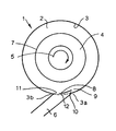
- a bearing housing 1 is depicted in the drawing.
- This housing 1 comprises a chamber 2 having an outer wall 3 about a bearing 4 which rotates in the direction of arrowhead 5.
- the housing 1 incorporates an oil scavenge out-take 6 positioned generally at the bottom dead centre of the housing 1 but angled to take account of the centrifugal draught effect provided by rotation of the bearing 4 in the direction of arrowhead 5. It will be understood as described previously, rotation of the bearing 5 will generally throw off or spray oil from an outer peripheral bearing surface 7 and this dispersed oil will be propelled towards the outer wall 3 of the chamber 2.
- the surface of the wall 3 towards the bearing 4 will normally incorporate a volute in order to accommodate that oil spray and to prevent potential back splash or flow towards the bearing 4 which may ingress into the bearing inhibiting good oil flow and therefore performance in terms of temperature and lubrication as well as degradation of the longer residing oil within the bearing 4.
- a baffle 8 is provided across the chordal arc presented by the out-take 6.
- the baffle 8 generally extends inwardly of the chamber 2 in order to create a radially spaced opening 10 between a leading edge 9 and a portion 3a of the outer wall 3. It will be appreciated that collected oil sprayed and incident within the volute or upon the simple surfaces of the wall 3 will pass through the spaced opening 10 into the out-take 6 for normal collection and processing as required.
- baffle 8 By use of the baffle 8 it will be understood that the centrifugal draft force created by rotation of the bearing 4 in the direction of arrowhead 5 is more substantially maintained with less pressure loss as a result of the opening of the out-take 6. Similarly, if the out-take 6 is coupled to a vacuum pump the effect of that pump is limited to the cross-sectional area of the opening 10 and therefore is generally more focused.
- the outer wall 3 of the chamber 2 will be of a slight spiral cross-section such that the wall portion 3a has a spiral divergence from a circular cross-section or circumferential alignment with the opposing part 3b of the housing 1. It will be appreciated that typically the portion 3b is also the position upon which the baffle 8 is mounted.
- the baffle 8 will normally be held in a fixed position within a housing 1. Thus this position will define the spaced opening 10 and therefore the effective scoop of the out-take 6 with respect to scavenged oil within the cavity 2.
- the baffle 8 may be in circumferrial alignment with the wall 3 about part 3b or slightly within that circumferal line shown by broken line 12 in the drawing.
- the baffle 8 may be displaceable in order to vary the spaced opening 10 as required by particular operational circumstances with respect to the bearing 4. Displacement may be about a pivot between a mounting end of the baffle 8 upon the outer wall part 3b.
- the present invention also allows scavenging of oil as a film upon the inner surface of the wall 3 of the chamber 2. It will be understood that this wall oil film removes heat from the chamber walls and so can be detrimental. In such circumstances by use of the present baffle 8 it is possible to keep that oil film moving and scavenging back for collection and processing as required with a reduced residence time in the chamber 2. In general it is important to keep the oil flowing in order to avoid degradation by its exposure to high temperatures.
- the particular shape, angle and curvature of the baffle 8 will be determined by particular operational requirements of the invention within different sized and shaped bearing housings. Nevertheless, in deciding on the shape, angle and curvature of the baffle 8, generally the objective will be to avoid oil recirculating in the chamber 2 rather than being forced out of the scavenge out-take 6. By judicious choice of the shape in particular of the baffle 8, it is possible to direct the oil and oil/air mix close to the wall 3 into the scavenge out-take 6.
- the drain 11 may be needed to allow any oil that fails to be directed into the off-take 6 by the baffle 8 to still be drained out of the chamber 2 particularly when the bearing 4 is not operational, that is to say is not rotating in the direction of arrowhead 5 and at such times as shut down of a machine incorporating the bearing 4 and housing 1.
- the baffle 8 will generate a low pressure region at the top of the scavenge out-take pipe 6 such that oil and air flows into that pipe 6.
- the baffle 8 may be fixed dependent upon suspected operational requirements or the baffle displaceable in terms of particularly its directional angle relative to the out-take 6 in order to enhance oil/air flow into the off-take 6.
Landscapes
- Engineering & Computer Science (AREA)
- General Engineering & Computer Science (AREA)
- Mechanical Engineering (AREA)
- Rolling Contact Bearings (AREA)
- Sliding-Contact Bearings (AREA)
Claims (8)
- Lagergehäuse (1) mit einer Kammer (2), die einen Auslass (6) zur Ölspülung aufweist, wobei sich der Auslass (6) über einen Sehnenbogen der Kammer erstreckt und eine Ablenkplatte (8) über den Auslass (6) verläuft, wodurch eine radial beabstandete Öffnung (10) zwischen der Ablenkplatte (8) und einem Teil (3a) der Außenwand (3) der Kammer (2) in der Nähe des Vorderrandes (9) der Ablenkplatte (8) gebildet wird.
- Gehäuse nach Anspruch 1, bei welchem der Teil (3a) der Außenwand (3) benachbart zur Ablenkplatte (8) eine spiralförmige Divergenz besitzt.
- Gehäuse nach den Ansprüchen 1 oder 2, bei welchem die Ablenkplatte (8) derart ausgerichtet ist, dass sie konsistent mit dem Umfang der Kammer (2) verläuft.
- Gehäuse nach einem der Ansprüche 1, 2 oder 3, bei welchem ein Abzug (11) in der Ablenkplatte vorgesehen ist.
- Gehäuse nach Anspruch 4, bei welchem der Abzug (11) in der Nähe des Lagerendes (3b) der Ablenkplatte (8) an der Kammerwand (3) angeordnet ist.
- Gehäuse nach einem der vorhergehenden Ansprüche, bei welchem die Ablenkplatte (8) versetzbar ist, um den radialen Abstand der Öffnung (10) zu verändern.
- Gehäuse nach Anspruch 6, bei welchem die Ablenkplatte (8) dadurch versetzbar ist, dass das Montageende (3b) der Ablenkplatte (8) an der Kammerwand (3) schwenkbar angelenkt ist.
- Lageranordnung mit einem Lagergehäuse (1) nach einem der vorhergehenden Ansprüche und mit einem Lager (4), das im Betrieb rotiert, um Öl durch Zentrifugalwirkung auf die Außenwand (3) des Gehäuses (1) aufzusprühen.
Applications Claiming Priority (1)
| Application Number | Priority Date | Filing Date | Title |
|---|---|---|---|
| GBGB0414619.7A GB0414619D0 (en) | 2004-06-30 | 2004-06-30 | A bearing housing |
Publications (2)
| Publication Number | Publication Date |
|---|---|
| EP1612437A1 EP1612437A1 (de) | 2006-01-04 |
| EP1612437B1 true EP1612437B1 (de) | 2006-12-27 |
Family
ID=32843290
Family Applications (1)
| Application Number | Title | Priority Date | Filing Date |
|---|---|---|---|
| EP05253425A Ceased EP1612437B1 (de) | 2004-06-30 | 2005-06-03 | Lagergehäuse |
Country Status (4)
| Country | Link |
|---|---|
| US (2) | US7387445B2 (de) |
| EP (1) | EP1612437B1 (de) |
| DE (1) | DE602005000374T2 (de) |
| GB (1) | GB0414619D0 (de) |
Cited By (1)
| Publication number | Priority date | Publication date | Assignee | Title |
|---|---|---|---|---|
| US11162421B2 (en) | 2019-10-22 | 2021-11-02 | Pratt & Whitney Canada Corp. | Bearing cavity and method of evacuating oil therefrom |
Families Citing this family (19)
| Publication number | Priority date | Publication date | Assignee | Title |
|---|---|---|---|---|
| US7204875B2 (en) * | 2001-10-24 | 2007-04-17 | Pentron Clinical Technologies, Llc | Dental filling material |
| US7124857B2 (en) * | 2004-03-18 | 2006-10-24 | Pratt & Whitney Canada Corp. | Rotating shaft scavenging scoop |
| JP2006301289A (ja) * | 2005-04-20 | 2006-11-02 | Tokyo Ohka Kogyo Co Ltd | ネガ型レジスト組成物およびレジストパターン形成方法 |
| US7699530B2 (en) * | 2006-09-28 | 2010-04-20 | Pratt & Whitney Canada Corp. | Oil scavenge system for gas turbine engine bearing cavity |
| US8292510B2 (en) * | 2006-09-28 | 2012-10-23 | United Technologies Corporation | Dual mode scavenge scoop |
| US7789200B2 (en) | 2006-11-14 | 2010-09-07 | Rolls-Royce Corporation | Sump housing |
| US7878303B2 (en) * | 2006-11-14 | 2011-02-01 | Rolls-Royce Corporation | Lubrication scavenge system |
| GB2458937A (en) * | 2008-04-04 | 2009-10-07 | Rolls Royce Plc | Lubrication and scavenge system |
| GB0816562D0 (en) * | 2008-09-11 | 2008-10-15 | Rolls Royce Plc | Lubricant scavenge arrangement |
| GB2487891B (en) | 2009-11-13 | 2014-01-08 | Otis Elevator Co | Bearing cartridge and elevator machine assembly |
| US8500332B2 (en) | 2010-05-05 | 2013-08-06 | Siemens Industry, Inc. | Self pumping oil film bearing |
| US8342753B2 (en) | 2010-06-08 | 2013-01-01 | Siemens Industry, Inc. | Venturi drain for self-pumping bearing rolling mills |
| US9051878B2 (en) | 2011-06-22 | 2015-06-09 | Hamilton Sundstrand Corporation | Engine bearing compartment |
| US9404381B2 (en) | 2012-09-04 | 2016-08-02 | United Technologies Corporation | Turbine engine transmission gutter |
| FR3030616B1 (fr) * | 2014-12-22 | 2019-03-29 | Safran Aircraft Engines | Support de palier pour turbomachine, notamment turboreacteur |
| EP3239481A1 (de) | 2016-04-27 | 2017-11-01 | Rolls-Royce plc | Ölkammerwand mit durchgangsöffnungen |
| US11719127B2 (en) | 2019-10-23 | 2023-08-08 | Raytheon Technologies Corporation | Oil drainback assembly for a bearing compartment of a gas turbine engine |
| US11970972B2 (en) * | 2019-10-23 | 2024-04-30 | Rtx Corporation | Windage blocker for oil routing |
| US11788433B2 (en) | 2021-10-26 | 2023-10-17 | Pratt & Whitney Canada Corp. | Lubrication system of aircraft engine |
Family Cites Families (21)
| Publication number | Priority date | Publication date | Assignee | Title |
|---|---|---|---|---|
| GB1050391A (de) * | ||||
| US1352298A (en) * | 1920-09-07 | Lubricant distributer and filter for internal-combustion engines | ||
| GB191500638A (en) * | 1915-01-15 | 1915-09-23 | Albion Motor Car Co Ltd | Improvements in Oil-returning Devices for Bearings. |
| US1230815A (en) * | 1916-09-20 | 1917-06-19 | Frank A Smith | Splash system of lubrication. |
| US2650671A (en) * | 1952-09-25 | 1953-09-01 | Gen Electric | Oil discharge passage arrangement for high-speed bearings |
| CH393003A (de) * | 1962-04-13 | 1965-05-31 | Oerlikon Maschf | Horizontales Gleitlager |
| GB2043799B (en) * | 1979-03-05 | 1983-03-16 | Rolls Royce | Draining oil from bearing |
| FR2471813B1 (fr) * | 1979-12-21 | 1985-10-11 | Rolls Royce | Dispositif de traitement de fluide |
| GB2135740B (en) * | 1983-02-11 | 1986-02-12 | Rolls Royce | Gas turbine engine lubrication systems |
| US4525995A (en) * | 1983-04-04 | 1985-07-02 | Williams International Corporation | Oil scavening system for gas turbine engine |
| US4630711A (en) * | 1984-06-27 | 1986-12-23 | Societe Anonyme D.B.A. | Device for lubricating a geartrain |
| US4683714A (en) * | 1986-06-17 | 1987-08-04 | General Motors Corporation | Oil scavenge system |
| DE3705607A1 (de) * | 1987-02-21 | 1988-09-01 | Porsche Ag | Lagerung eines achsantrieb-kegelritzels |
| DE4041389A1 (de) * | 1990-12-21 | 1992-06-25 | Kugelfischer G Schaefer & Co | Vorrichtung zum entfernen von oel aus ringraeumen |
| DE59302524D1 (de) * | 1992-07-07 | 1996-06-13 | Siemens Ag | Einrichtung zur abführung von schmiermittel aus einer lageranordnung |
| US5489190A (en) * | 1994-07-29 | 1996-02-06 | Alliedsignal Inc. | Dynamic oil scavenge system |
| US6286476B1 (en) * | 1996-04-30 | 2001-09-11 | Sanshin Kogyo Kabushiki Kaisha | Engine lubricating system |
| JP3516803B2 (ja) | 1996-04-30 | 2004-04-05 | ヤマハマリン株式会社 | 船外機のエンジン |
| GB0218849D0 (en) * | 2002-08-14 | 2002-09-25 | Rolls Royce Plc | Lubrication system for gas turbine engine |
| US6996968B2 (en) * | 2003-12-17 | 2006-02-14 | United Technologies Corporation | Bifurcated oil scavenge system for a gas turbine engine |
| GB0414235D0 (en) * | 2004-06-25 | 2004-07-28 | Rolls Royce Plc | A lubrication arrangement |
-
2004
- 2004-06-30 GB GBGB0414619.7A patent/GB0414619D0/en not_active Ceased
-
2005
- 2005-06-03 DE DE602005000374T patent/DE602005000374T2/de not_active Expired - Lifetime
- 2005-06-03 EP EP05253425A patent/EP1612437B1/de not_active Ceased
- 2005-06-06 US US11/144,636 patent/US7387445B2/en not_active Expired - Fee Related
-
2008
- 2008-05-23 US US12/126,512 patent/US7811001B2/en not_active Expired - Fee Related
Cited By (1)
| Publication number | Priority date | Publication date | Assignee | Title |
|---|---|---|---|---|
| US11162421B2 (en) | 2019-10-22 | 2021-11-02 | Pratt & Whitney Canada Corp. | Bearing cavity and method of evacuating oil therefrom |
Also Published As
| Publication number | Publication date |
|---|---|
| DE602005000374D1 (de) | 2007-02-08 |
| EP1612437A1 (de) | 2006-01-04 |
| US7811001B2 (en) | 2010-10-12 |
| US7387445B2 (en) | 2008-06-17 |
| DE602005000374T2 (de) | 2007-04-19 |
| US20080219613A1 (en) | 2008-09-11 |
| US20060002645A1 (en) | 2006-01-05 |
| GB0414619D0 (en) | 2004-08-04 |
Similar Documents
| Publication | Publication Date | Title |
|---|---|---|
| US7811001B2 (en) | Bearing housing | |
| US5632608A (en) | Pump oil mister with reduced windage | |
| AU2004201489B2 (en) | Diesel engine water pump with improved water seal | |
| US5591020A (en) | Pump oil mister | |
| JP5699058B2 (ja) | 水冷エンジン | |
| JP2007517178A (ja) | 互いに接触しないように設けられる排斥環を持つ滑り軸受 | |
| SE441384B (sv) | Lagerberare for en maskin roterande med hog hastighet, sasom en turbokompressor | |
| US20080175704A1 (en) | Pump oil mister with improved service life | |
| JP4510638B2 (ja) | 玉軸受およびこの形式の軸受が装備された真空ポンプ | |
| US6918746B2 (en) | Diesel engine water pump with thrust bearing preload | |
| AU2004201493B9 (en) | Diesel engine water pump with improved oil control | |
| US4448552A (en) | Bearing lubrication system | |
| US20160348686A1 (en) | Screw pump and impeller fan assemblies and method of operating | |
| US8506238B2 (en) | Water pump with housing/impeller to enhance seal performance | |
| CN113970057B (zh) | 排脂装置、轴承组件以及风力发电机组 | |
| CN204783793U (zh) | 自平衡式多级离心泵定位端轴承箱体结构及轴承组件 | |
| JP2008240522A (ja) | タービン軸の油切り装置 | |
| JP4625366B2 (ja) | 立軸水車の軸受冷却装置 | |
| KR100371767B1 (ko) | 터보차저의 윤활구조 | |
| JPS6357875A (ja) | 水車主軸受のオイルミスト漏洩防止装置 | |
| JP3332665B2 (ja) | ディスク給油式軸受装置 | |
| JPH05936U (ja) | 内燃機関用過給機 | |
| JPH03206365A (ja) | 主軸封水部の土砂流入防止装置 |
Legal Events
| Date | Code | Title | Description |
|---|---|---|---|
| PUAI | Public reference made under article 153(3) epc to a published international application that has entered the european phase |
Free format text: ORIGINAL CODE: 0009012 |
|
| 17P | Request for examination filed |
Effective date: 20050916 |
|
| AK | Designated contracting states |
Kind code of ref document: A1 Designated state(s): AT BE BG CH CY CZ DE DK EE ES FI FR GB GR HU IE IS IT LI LT LU MC NL PL PT RO SE SI SK TR |
|
| AX | Request for extension of the european patent |
Extension state: AL BA HR LV MK YU |
|
| GRAP | Despatch of communication of intention to grant a patent |
Free format text: ORIGINAL CODE: EPIDOSNIGR1 |
|
| AKX | Designation fees paid |
Designated state(s): DE FR GB |
|
| GRAS | Grant fee paid |
Free format text: ORIGINAL CODE: EPIDOSNIGR3 |
|
| GRAA | (expected) grant |
Free format text: ORIGINAL CODE: 0009210 |
|
| AK | Designated contracting states |
Kind code of ref document: B1 Designated state(s): DE FR GB |
|
| REG | Reference to a national code |
Ref country code: GB Ref legal event code: FG4D |
|
| REF | Corresponds to: |
Ref document number: 602005000374 Country of ref document: DE Date of ref document: 20070208 Kind code of ref document: P |
|
| ET | Fr: translation filed | ||
| PLBE | No opposition filed within time limit |
Free format text: ORIGINAL CODE: 0009261 |
|
| STAA | Information on the status of an ep patent application or granted ep patent |
Free format text: STATUS: NO OPPOSITION FILED WITHIN TIME LIMIT |
|
| 26N | No opposition filed |
Effective date: 20070928 |
|
| REG | Reference to a national code |
Ref country code: FR Ref legal event code: PLFP Year of fee payment: 11 |
|
| REG | Reference to a national code |
Ref country code: FR Ref legal event code: PLFP Year of fee payment: 12 |
|
| REG | Reference to a national code |
Ref country code: FR Ref legal event code: PLFP Year of fee payment: 13 |
|
| REG | Reference to a national code |
Ref country code: FR Ref legal event code: PLFP Year of fee payment: 14 |
|
| PGFP | Annual fee paid to national office [announced via postgrant information from national office to epo] |
Ref country code: FR Payment date: 20180626 Year of fee payment: 14 |
|
| PGFP | Annual fee paid to national office [announced via postgrant information from national office to epo] |
Ref country code: DE Payment date: 20180627 Year of fee payment: 14 Ref country code: GB Payment date: 20180627 Year of fee payment: 14 |
|
| REG | Reference to a national code |
Ref country code: DE Ref legal event code: R119 Ref document number: 602005000374 Country of ref document: DE |
|
| GBPC | Gb: european patent ceased through non-payment of renewal fee |
Effective date: 20190603 |
|
| PG25 | Lapsed in a contracting state [announced via postgrant information from national office to epo] |
Ref country code: GB Free format text: LAPSE BECAUSE OF NON-PAYMENT OF DUE FEES Effective date: 20190603 Ref country code: DE Free format text: LAPSE BECAUSE OF NON-PAYMENT OF DUE FEES Effective date: 20200101 |
|
| PG25 | Lapsed in a contracting state [announced via postgrant information from national office to epo] |
Ref country code: FR Free format text: LAPSE BECAUSE OF NON-PAYMENT OF DUE FEES Effective date: 20190630 |