EP1612457A2 - Stufenloses Getriebe und Verfahren dafür - Google Patents
Stufenloses Getriebe und Verfahren dafür Download PDFInfo
- Publication number
- EP1612457A2 EP1612457A2 EP05017825A EP05017825A EP1612457A2 EP 1612457 A2 EP1612457 A2 EP 1612457A2 EP 05017825 A EP05017825 A EP 05017825A EP 05017825 A EP05017825 A EP 05017825A EP 1612457 A2 EP1612457 A2 EP 1612457A2
- Authority
- EP
- European Patent Office
- Prior art keywords
- face
- pulley
- belt
- rotational axis
- variable speed
- Prior art date
- Legal status (The legal status is an assumption and is not a legal conclusion. Google has not performed a legal analysis and makes no representation as to the accuracy of the status listed.)
- Granted
Links
Images


Classifications
-
- F—MECHANICAL ENGINEERING; LIGHTING; HEATING; WEAPONS; BLASTING
- F16—ENGINEERING ELEMENTS AND UNITS; GENERAL MEASURES FOR PRODUCING AND MAINTAINING EFFECTIVE FUNCTIONING OF MACHINES OR INSTALLATIONS; THERMAL INSULATION IN GENERAL
- F16H—GEARING
- F16H63/00—Control outputs from the control unit to change-speed- or reversing-gearings for conveying rotary motion or to other devices than the final output mechanism
- F16H63/02—Final output mechanisms therefor; Actuating means for the final output mechanisms
- F16H63/04—Final output mechanisms therefor; Actuating means for the final output mechanisms a single final output mechanism being moved by a single final actuating mechanism
- F16H63/06—Final output mechanisms therefor; Actuating means for the final output mechanisms a single final output mechanism being moved by a single final actuating mechanism the final output mechanism having an indefinite number of positions
- F16H63/067—Final output mechanisms therefor; Actuating means for the final output mechanisms a single final output mechanism being moved by a single final actuating mechanism the final output mechanism having an indefinite number of positions mechanical actuating means
-
- F—MECHANICAL ENGINEERING; LIGHTING; HEATING; WEAPONS; BLASTING
- F16—ENGINEERING ELEMENTS AND UNITS; GENERAL MEASURES FOR PRODUCING AND MAINTAINING EFFECTIVE FUNCTIONING OF MACHINES OR INSTALLATIONS; THERMAL INSULATION IN GENERAL
- F16H—GEARING
- F16H55/00—Elements with teeth or friction surfaces for conveying motion; Worms, pulleys or sheaves for gearing mechanisms
- F16H55/32—Friction members
- F16H55/52—Pulleys or friction discs of adjustable construction
- F16H55/56—Pulleys or friction discs of adjustable construction of which the bearing parts are relatively axially adjustable
-
- F—MECHANICAL ENGINEERING; LIGHTING; HEATING; WEAPONS; BLASTING
- F16—ENGINEERING ELEMENTS AND UNITS; GENERAL MEASURES FOR PRODUCING AND MAINTAINING EFFECTIVE FUNCTIONING OF MACHINES OR INSTALLATIONS; THERMAL INSULATION IN GENERAL
- F16H—GEARING
- F16H7/00—Gearings for conveying rotary motion by endless flexible members
- F16H7/08—Means for varying tension of belts, ropes or chains
- F16H7/0827—Means for varying tension of belts, ropes or chains for disconnecting the drive
-
- B—PERFORMING OPERATIONS; TRANSPORTING
- B60—VEHICLES IN GENERAL
- B60Y—INDEXING SCHEME RELATING TO ASPECTS CROSS-CUTTING VEHICLE TECHNOLOGY
- B60Y2200/00—Type of vehicle
- B60Y2200/20—Off-Road Vehicles
- B60Y2200/22—Agricultural vehicles
- B60Y2200/223—Ridable lawn mowers
-
- F—MECHANICAL ENGINEERING; LIGHTING; HEATING; WEAPONS; BLASTING
- F16—ENGINEERING ELEMENTS AND UNITS; GENERAL MEASURES FOR PRODUCING AND MAINTAINING EFFECTIVE FUNCTIONING OF MACHINES OR INSTALLATIONS; THERMAL INSULATION IN GENERAL
- F16H—GEARING
- F16H9/00—Gearings for conveying rotary motion with variable gear ratio, or for reversing rotary motion, by endless flexible members
- F16H9/02—Gearings for conveying rotary motion with variable gear ratio, or for reversing rotary motion, by endless flexible members without members having orbital motion
- F16H9/04—Gearings for conveying rotary motion with variable gear ratio, or for reversing rotary motion, by endless flexible members without members having orbital motion using belts, V-belts, or ropes
- F16H9/12—Gearings for conveying rotary motion with variable gear ratio, or for reversing rotary motion, by endless flexible members without members having orbital motion using belts, V-belts, or ropes engaging a pulley built-up out of relatively axially-adjustable parts in which the belt engages the opposite flanges of the pulley directly without interposed belt-supporting members
- F16H9/16—Gearings for conveying rotary motion with variable gear ratio, or for reversing rotary motion, by endless flexible members without members having orbital motion using belts, V-belts, or ropes engaging a pulley built-up out of relatively axially-adjustable parts in which the belt engages the opposite flanges of the pulley directly without interposed belt-supporting members using two pulleys, both built-up out of adjustable conical parts
- F16H9/18—Gearings for conveying rotary motion with variable gear ratio, or for reversing rotary motion, by endless flexible members without members having orbital motion using belts, V-belts, or ropes engaging a pulley built-up out of relatively axially-adjustable parts in which the belt engages the opposite flanges of the pulley directly without interposed belt-supporting members using two pulleys, both built-up out of adjustable conical parts only one flange of each pulley being adjustable
Definitions
- the present invention relates to power equipment, including but not limited to mowers, tillers, snow blowers, and tractors, and more particularly, to a variable speed transmission and method for using the variable speed transmission.
- the France Reductor VST includes a first belt that is attached between a drive pulley on the engine output shaft and a driven pulley on a rotational shaft.
- a second pulley is attached to the same rotational shaft as the driven pulley and is locked and rotates synchronously with the driven pulley.
- a second belt is attached between the second pulley and a second driven pulley connected to a transmission shaft.
- the transmission shaft is connected to a transmission that transmits rotational power to a drive wheel or other drive mechanism.
- a clutch located in this transmission can be actuated to engage/disengage the transmission and transmit/disengage rotational power to the drive mechanism.
- a plate supporting the rotational shaft can be moved against the bias of a spring to tension and loosen the first belt and second belt, respectively.
- the first driven pulley and the second drive pulley (both of which are located on the same rotational shaft) have variable width grooves that are caused to vary when their respective belts are tensioned and loosened. Accordingly, when the first belt is tensioned, the first belt moves deeper into the groove of the first pulley towards the rotational axis of the rotational shaft, thus rotating the rotational shaft at ever increasing speeds as tension in the belt increases.
- the groove in the second drive pulley becomes narrower and the second belt moves out of the groove and away from the rotational axis of the rotational shaft, thus increasing the speed of the second belt and ultimately increasing the speed of the drive mechanism.
- Two belts are required in such a system to provide the necessary increase in variable speed output for the power equipment drive mechanism.
- two control mechanisms are necessary such that one control mechanism can actuate the transmission and one control mechanism can vary the speed of the transmission.
- VST system that is commonly used in power equipment includes a hydrostatic transmission for varying the speed output to a drive unit.
- a single control mechanism can be used to vary the speed of a drive unit from a neutral position to maximum speed.
- transmissions are relatively expensive to manufacture.
- maintenance and repair of such a system are significantly more difficult and expensive than maintenance and repair of belt drive and/or geared transmission systems.
- the present invention is directed to a variable speed transmission that substantially obviates one or more of the problems due to limitations and disadvantages of the related art.
- An object of the present invention is to provide an efficient, inexpensive and compact variable speed transmission that can be actuated from a neutral position through a full speed position by a single actuator mechanism.
- Another object of the invention is to incorporate the belt into the clutch mechanism of the variable speed transmission.
- a further object of the invention is to provide a compact single actuation variable speed transmission that is capable of producing a relatively high level of output speed
- Another object of the present invention is to provide a compact assembly that can be easily and adequately shielded and requires as few parts as possible.
- a still further obj ect of the present invention is to minimize the number of pulleys and belts necessary, and to provide a variable speed transmission that uses a single belt connected between two pulleys such that the amount of moving parts is reduced and the possibility of malfunctions are reduced.
- Another object of the invention is to vary the speed of a drive mechanism for power equipment in a smooth and reliable manner.
- a still further object of the invention is to provide a compact single actuator mechanism that controls the output speed to a drive mechanism from zero to a maximum speed by moving the actuator mechanism in a single uniform motion.
- Another object of the invention is to incorporate the variable speed transmission into the drive shaft of a motor such that a compact arrangement of the transmission can be achieved.
- a variable speed transmission includes: a first pulley having a rotational axis and including a first face and a second face, the first face being movable with respect to the second face; a belt located adjacent the first face and the second face of the first pulley; and an actuator located adjacent the first pulley and adapted to move the first face to move with respect to the second face between a neutral position, an intermediate position and a full speed position, the neutral position defined by the first face being located at a first position with respect to the second face, and the first face being rotatable relative to the second face, the intermediate position defined by the first face being located at a second position that is closer to the second face than when the first face is located at the first position, the belt being in frictional engagement with the first face and second face such that motion of one of the first face, second face and belt causes another one of the first face, second face and belt to move, and the full speed position defined by
- the invention also includes a variable speed transmission for continuously varying the output speed of a drive wheel from zero to an upper speed limit, which includes: a single control mechanism capable of controlling the speed of the drive wheel from zero to the upper speed limit; an actuator connected to the control mechanism; and a drive train operationally connected between the control mechanism and the drive wheel, wherein the drive train includes a first and second pulley and no more than one belt.
- the invention can include a variable speed transmission, that includes: a first pulley having a rotational axis and including a first face and a second face, the first face being movable with respect to the second face; a second pulley having a second pulley rotational axis and including a primary face and a secondary face; a belt located on the first pulley and second pulley; and an actuator located adjacent the first pulley and adapted to move the first face with respect to the second face between a neutral position and a drive position, the neutral position is defined by the first face being located at a first position with respect to the second face, and the first face being rotatable with respect to the second face, the drive position is defined by the first face and second face being frictionally engaged with the belt such that the first face, second face and belt rotate together.
- the invention can also include a variable speed transmission, including: a first pulley having a rotational axis and including a first face and a second face, the first face being movable with respect to the second face; a second pulley having a second pulley rotational axis and including a primary face and a secondary face, the primary face being movable with respect to the secondary face along the second pulley rotational axis; a biasing mechanism located adjacent one of the primary face and secondary face of the second pulley and adapted to bias the primary face towards the secondary face; a belt located on the first pulley and second pulley; and an actuator located adjacent the first pulley and adapted to move the first face with respect to the second face between a neutral position and a drive position, the neutral position is defined by the first face being located at a first position with respect to the second face, and the first face being rotatable with respect to the second face, the drive position is defined by the first face and second face being frictionally engaged with the belt such that the
- the invention can also include a method for using a variable speed transmission that includes a first pulley having a rotational axis, a first face and a second face, the first face being movable along the rotational axis with respect to the second face, a second pulley having a second pulley rotational axis, a primary face and a secondary face, the primary face being movable with respect to the secondary face along the second pulley rotational axis, a belt connected between the first pulley and the second pulley, including: driving one of the first face, the second face and the belt about the rotational axis of the first pulley; moving the first face along the rotational axis and relative to the second face such that a portion of each of the first face and the second face frictionally releases from the belt to cause one of the first face, the second face and the belt to begin movement relative to another one of the first face, the second face and the belt.
- the invention can also include a method for using a variable speed transmission to drive a propulsion mechanism on a piece of power equipment, including: providing a control mechanism that is connected to a drive train which drives the propulsion mechanism, the drive train including a first pulley having a rotational axis, a first sheave and a second sheave, and a belt having an inner surface located around the first pulley; permitting the first sheave to remain substantially stationary relative to the second sheave; rotating the first sheave of the first pulley with respect to the belt; and engaging the belt with the first sheave of the first pulley with enough force to begin movement of the belt about the first pulley.
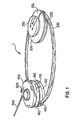
- FIG. 1 illustrates an isometric top view of a preferred embodiment of the variable speed transmission (VST).
- the VST includes a first pulley 100 and actuator 400 connected to an engine output drive shaft 600.
- a belt 300 connects the first pulley 100 to a second pulley 200, which in turn is connected to a drive mechanism for the associated piece of power equipment.
- the rotational energy from the engine output drive shaft 600 can be transmitted to the drive mechanism via a first pulley 100, actuator 400, belt 300 and a second pulley 200.
- a control mechanism 500 can be attached to the actuator 400 to vary the output speed of the drive mechanism from about zero to an engagement/intermediate position speed and then proceed to a maximum or full speed.
- the control mechanism 500 varies the range of output speed of the drive mechanism by causing the actuator 400 to change respective the groove width of the first and second pulleys 100, 200, thus changing the radius of rotation o: the belt 300 about the first and second pulleys 100 and 200, as explained in greater detail below.
- the present invention provides a neutral position in which the rotational energy of the drive shaft 600 is disengaged from the drive mechanism of the power equipme This neutral position is realized by using the belt 300 as a "clutch,” which will also be explained in greater detail below.
- the control mechanism 5 causes the actuator 400 to be at its maximum speed position.
- the U-shaped actuator b is pivoted to its furthest angled position with respect to the U-shaped handle, the actuator is its neutral position.
- the operator can propel the power equipment from zero to maximum speed by squeezing and/or otherwise moving the U-shaped actuator bar to pivot i with respect to the U-shaped handle.
- other actuators such as a rotary knob or pivoting lever could be used in place of the U-shaped bar actuator to control the speed of the power equipment between zero and maximum speed.
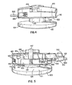
- the actuator 400 can include a first actuator plate 410 and a second actuator plate 420, each of which can rotate with respect to the other upon activation the control mechanism 500.
- the first actuator plate 410 can include an extension lock member 417 on its top surface 413 for locking the first actuator plate to the housing or other element of the power equipment.
- the second actuator plate 420 will be able to rotate with respect to both the first actuator plate 410 and the power equipment device in general.
- the first actuator plate 410 could be rotatable with respect to both the second actuator plate 420 and the power equipment device in general.
- Bearings 404 permit both the first and second actuator plate to rotate relative to the drive shaft 600 located in shaftway 40 of the actuator plates 410 and 420.
- the bearings 404 can be the same or different style bearings and can be selected to conform to the necessary performance characteristics desire for a particular application of the invention. In addition, when economical considerations mandate, it is possible in some circumstances to not use bearings or consolidate various bearings.
- a retaining clip 601 can be provided to keep the actuator 400 in position on the drive shaft 600.
- the control mechanism 500 is preferably connected to the actuator 400 by an attachment ball 517 that is locked into a mating actuator cutout 426 in the second actuator plate 420.
- a cable retainer 510 can be fixed to an actuator extension 418 on the first actuatc plate 410 by inserting a lock nub 512 that extends from the cable retainer 510 into an apertu in the extension 418 of the first actuator plate 410.
- a control cable (or control line) 515 located within the cable retainer 510 can move relative to the cable retainer 510 and the first actuator plate 410. Accordingly, movement of the control line 515 causes the second actuat plate 420 to move/rotate with respect to the first actuator plate 410.
- a ball/ramp mechanism 443 (see Figure 3) can be used in combination with an actuator spring 430 to bias the second actuator plate 420 to its initial position with respect to the first actuator plate 410 when tens in the control line 515 is released.
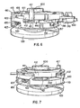
- the ball/ramp mechanism 443 includes balls 440 located between the actuator plate 410 and 420 which ride up respective ramps 441 located in one of the first and second actua plates 410 and 420. As the second plate 420 rotates with respect to the first actuator plate 4 the balls 403 ride up the ramps 441 and cause the second actuator plate 420 to separate and move away from the first actuator plate 410 against the bias of springs 430.
- Springs 430 are attached to the first actuator plate 410 and extend through slots 427 located in a springway portion 423 of the second actuator plate 420. The slots 427 are shaped to allow the springs 430 to ride along the lower surface 424 of the second actuator plate 420 as the second actua plate 420 rotates relative to the first actuator plate 410.
- the springs 430 bias the second actuator plate 420 towards the first actuator plate 410 throughout rotation of the plates.
- the springs 430 are connected to the first actuator plate 410 by inserting a portion of each spring 430 into a spring lockhole 416 in the top surface of the first actuator plate 410.
- the spring extends downward through a spring slot 415 in the first actuator plate 410.
- the first pulley 100 includes a first sheave 110 and a second sheave 120 which form a groove 130 therebetween.
- the second sheave 120 can be connected to rotate with the drive shaft 600 such that both the second sheave 120 and drive shaft 600 rotate with respect to the first sheave 110 of the first pulley 100.
- the first sheave 110 can also rotate with respect to the drive shaft 600 and with respect to the second actuator plate 420.
- Bearings 404 can be provided between both the first sheave 110 and drive shaft 600 and between the first sheave 110 and second actuator plate 420 to facilitate their relative rotation.
- the second actuator plate 420 moves downward by action of the control mechanism 500, it forces the first sheave 110 of the first pulley towards the second sheave 120 of the first pulley, which decreases the width of the groove 130 of the first pulley 100.
- the belt 300 is engaged with a face 121 of the second sheave 120 of the first pulley 100.
- the belt 300 becomes tensioned as it engages the face 121 and begins to rotate about the rotational axis of the first pulley 100 due to frictional force between the rotating face 121 and belt surface. This action is what is referred to above as using the belt 300 as a clutch mechanism.
- the first pulley sheave 110 can also include an extension surface 112 that extends along the rotational axis of the drive shaft 600 and between the first angled surface 114 and second angled surface 124 of the first and second sheaves 110, 120.
- the belt 300 tension causes the groove in the first pulley to return to its widest position, and the belt 300 rests on the extension surface 112.
- the drive mechanism remains effectively at a geared idle or geared neutral state.
- the belt 300 is preferably connected between and supplies power from the drive shaft 600 to the second pulley 200.
- the second pulley 200 can be connected to a drive mechanism of the power equipment for propelling the equipment.
- an attachment disk 250 can be attached to the hub 227 of the second pulley second sheave 220 to keep the first and second sheaves 210 and 220 together.
- the attachment disk 250 can be attached to the hub 227 by a number of screws 253 that extend though holes 251 in the disk 250 and attach to screw holes 223 in the hub 227 of the second sheave 220.
- Various shaped hubs can be used in the invention, including a single key hub.
- a spring 240 which can be a diaphragm type or belleville spring, can be located between the attachment disk 250 and a top surface 216 of the first sheave 210 to bias the first sheave 210 towards the second sheave 220 of the second pulley.
- the spring 240 rides along the outside of collar 217 in the second pulley first sheave 210 and can include an upper ring 241 and lower ring 242 separated from each other by an intermediate leaflet 243.
- the upper and lower rings 241 and 242 lie flat on the lower surface of the attachment disk 250 and the top surface 216 of the first sheave 210, respectively.
- the spring 240 permits the groove 230 formed between the first sheave 210 and second sheave 220 of the second pulley 200 to vary in width in accordance with the tension in the belt 300.
- the belt 300 can ride between a first face 211 of the first sheave 210 and a second face 221 of the second sheave 220 of the second pulley 200. Angled surfaces 214 and 224 located on the first and second face 211 and 221, respectively, tend to move the belt away from the rotational axis of the second pulley as the first sheave 210 and second sheave 220 of the second pulley 200 move towards each other under the bias of spring 240. Thus, when tension decreases in the belt 300, the bias of the spring 240 moves the first and second sheaves 210 and 220 together to decrease the width of groove 230.
- the belt 300 is then caused to move further from the rotational axis of the second pulley, thus slowing the rotational speed of both the second pulley 200 and the drive mechanism to which the second pulley 200 is connected.
- the belt 300 is tensioned (e.g., when the control mechanism 500 is activated to cause the actuator 400 to move the first pulley sheaves 110 and 120 towards each other to "clutch" the belt 300 into motion/tension)
- the tension in the belt 300 overcomes the bias in the spring 240 to separate the first and second sheaves 210 and 220 of the second pulley, thus widening the groove 230.
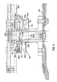
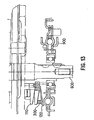
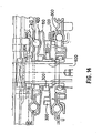
- the first pulley 100 actuator 400 can be configured to attach between a mower blade 700 and the lower housing 800 of a mower.
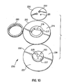
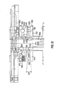
- the right half of the split view of Fig. 11 and 12 depicts an embodiment in which many of the pulley 100 and actuator 400 components are molded components and the first pulley is in the maximum speed position ( e . g . , the actuator 400 is actuated and the first sheave 110 and second sheave 120 of the first pulley 100 are at their minimum separation distance and the belt 300 is furthest from the rotational axis of the drive shaft 600).
- the left half of the split view of Fig. 11 depicts an embodiment in which many components of the pulley 100 and actuator 400 are plate components and the first pulley 100 and actuator 400 are in a neutral position. However, belt 300 is shown at both a neutral and high speed position in this portion of the split figure.
- a preferable range for the outer diameter of the first pulley 100 as measured from the outside of the belt varies from 48.2mm at low speed/neutral, to 68.2 at mid speed, to 88.2mm at maximum speed.
- a preferable range for the outer diameter of the second pulley 200 as measured from the outside of the belt varies from 103mm at low speed/neutral, to 83.5mm at mid-speed, to 64mm at maximum speed.
- the specific value for the diameter of the first and second pulley can change depending on the particular application or desired speed ratio.
- the horsepower required for driving a mower engine at 3100 rpm which includes a first and second pulley with the above noted diameter variances between neutral and maximum speed is approximately 0.16hp when cruising, and 0.47hp at maximum load.
- the ground speed can vary from 1.22mph to 3.61mph in the preferred embodiment of the invention.
- the force required to actuate the actuator 400 can be relatively low such that a low tension force is required in the cable 515.
- This low tension force provides good operating stability and durability for the variable speed transmission and also permits easy operation by users of the device.
- the invention has been described with respect to preferred embodiments of the invention, it should be understood that many variations of these embodiments fall within the scope and spirit of the claimed invention.
- the specific speed, horsepower and diameter values described above could be changed to meet a particular application or to fulfill different objectives.
- the invention could include an embodiment in which the actuator and first pulley are attached to a driven shaft, and the second pulley as described above could be attached to the drive shaft or engine output shaft.
- the invention could also be mounted in many different ways to the power equipment, including under the housing, above the housing and even on the side of a piece of power equipment.
- the actuator is disclosed as including a ball/ramp device 243 for causing separation of the actuator plates.
- other known actuator devices could be incorporated in the present invention without departing from the spirit and scope of the invention.
- a Blade Brake Clutch mechanism as disclosed in applicant's co-pending U.S. Patent Application No.: 09/628,447, which is hereby incorporated by reference, could be used in place of the actuator mechanism disclosed above.
- the actuator could also be attached to the power equipment in different manners.
- the second (or lower) actuator plate could be fixed to the power equipment, and the first (or top) actuator plate could be connected to a control device and rotate with respect to the power equipment and second actuator plate.
- the second pulley is disclosed as having a first sheave and second sheave that are rotationally locked with respect to each other, it is within the scope of the present invention to include first and second sheaves that can rotate with respect to each other in the second pulley.
- first and second sheaves that can rotate with respect to each other in the second pulley.
- the first sheave and second sheave of the first pulley are disclosed as being separate from each other. However, it is contemplated that these structures could contact each other or be separated by a bearing or the like.
- the extension portion (or hub portion) of the first sheave of the first pulley could conceivably be disconnected from the first sheave and ride freely on the drive shaft.
- the extension portion of the first sheave could possibly be eliminated from the configuration depending on the type of belt used and the friction parameters of all moving parts.
- the actuator could be activated to cause a first or second sheave of the driven pulley to engage with the moving belt at the driven pulley side of the transmission.
- the belt would be moving and the driven pulley would "clutch" the moving belt to effect the variable speed transmission.
- the relative sizes of the first and second pulley and belt can be varied in accordance with the desired speed ratios and in accordance with the design parameters of specific power equipment.
- the actuator size can be varied as well.
- the materials out of which the system is manufactured also varies widely, and includes cast metals, metal plating, plastics, rubbers, ceramic, etc. The selection of materials will effect the amount of friction necessary to engage or clutch the belt, and therefore could be a significant consideration in designing the invention for a particular application.
- control device could also be configured differently and remain within the scope of the present invention.
- control mechanism could be a magnetic, hydraulic, pneumatic, bellcrank or other type actuation device, and possibly could be a solenoid or other electronic actuator device.
Landscapes
- Engineering & Computer Science (AREA)
- General Engineering & Computer Science (AREA)
- Mechanical Engineering (AREA)
- Transmissions By Endless Flexible Members (AREA)
- Transmission Devices (AREA)
- Steroid Compounds (AREA)
- Gear-Shifting Mechanisms (AREA)
- Friction Gearing (AREA)
Applications Claiming Priority (2)
| Application Number | Priority Date | Filing Date | Title |
|---|---|---|---|
| US09/739,795 US6592478B2 (en) | 2000-12-20 | 2000-12-20 | Variable speed transmission and method of use |
| EP01993271A EP1343984B1 (de) | 2000-12-20 | 2001-12-18 | Stufenloses getriebe und verfahren dafür |
Related Parent Applications (1)
| Application Number | Title | Priority Date | Filing Date |
|---|---|---|---|
| EP01993271A Division EP1343984B1 (de) | 2000-12-20 | 2001-12-18 | Stufenloses getriebe und verfahren dafür |
Publications (3)
| Publication Number | Publication Date |
|---|---|
| EP1612457A2 true EP1612457A2 (de) | 2006-01-04 |
| EP1612457A3 EP1612457A3 (de) | 2006-01-11 |
| EP1612457B1 EP1612457B1 (de) | 2008-03-12 |
Family
ID=24973810
Family Applications (2)
| Application Number | Title | Priority Date | Filing Date |
|---|---|---|---|
| EP01993271A Expired - Lifetime EP1343984B1 (de) | 2000-12-20 | 2001-12-18 | Stufenloses getriebe und verfahren dafür |
| EP05017825A Expired - Lifetime EP1612457B1 (de) | 2000-12-20 | 2001-12-18 | Stufenloses Getriebe und Verfahren dafür |
Family Applications Before (1)
| Application Number | Title | Priority Date | Filing Date |
|---|---|---|---|
| EP01993271A Expired - Lifetime EP1343984B1 (de) | 2000-12-20 | 2001-12-18 | Stufenloses getriebe und verfahren dafür |
Country Status (6)
| Country | Link |
|---|---|
| US (2) | US6592478B2 (de) |
| EP (2) | EP1343984B1 (de) |
| CN (1) | CN100406784C (de) |
| AT (2) | ATE305573T1 (de) |
| DE (2) | DE60133232T2 (de) |
| WO (1) | WO2002055901A2 (de) |
Families Citing this family (9)
| Publication number | Priority date | Publication date | Assignee | Title |
|---|---|---|---|---|
| FR2889866B1 (fr) * | 2005-07-29 | 2007-10-19 | France Reducteurs Soc Par Acti | Variateur de vitesse a courroie et engin automoteur a vitesse d'avancement variable equipe d'un tel variateur |
| CN102102743B (zh) * | 2005-12-01 | 2013-11-06 | 罗伯特·博世有限公司 | 操作无级变速装置的方法 |
| DE102007061028A1 (de) | 2007-12-18 | 2009-06-25 | Piv Drives Gmbh | Stufenlos verstellbares Kegelscheibengetriebe mit Zugmittelstrang |
| US8226508B2 (en) * | 2008-01-30 | 2012-07-24 | Honda Motor Co., Ltd. | Transmissions, drive systems and methods for using same |
| US20100072016A1 (en) * | 2008-08-26 | 2010-03-25 | Brian Aschenbrenner | Mechanical Clutch for V-Belt System |
| US9622407B2 (en) | 2012-02-13 | 2017-04-18 | Husqvarna Ab | All wheel drive, walk behind mower |
| US9326446B2 (en) * | 2014-03-12 | 2016-05-03 | Mtd Products Inc | Clutch assembly for a lawn maintenance vehicle |
| US9677648B2 (en) | 2015-01-14 | 2017-06-13 | The Toro Company | Walk-behind power equipment unit having all-wheel drive control system |
| CN111520450A (zh) * | 2020-06-16 | 2020-08-11 | 庄淇 | 工况自调节的摩擦与啮合混合型传动装置 |
Family Cites Families (32)
| Publication number | Priority date | Publication date | Assignee | Title |
|---|---|---|---|---|
| US1279547A (en) * | 1918-02-20 | 1918-09-24 | Henry Hueber | Variable-speed transmission. |
| DE1108037B (de) | 1958-10-31 | 1961-05-31 | Peugeot Cycles | Keilriemenwechselgetriebe |
| US3362242A (en) * | 1965-06-24 | 1968-01-09 | Outboard Marine Corp | Sheave drive |
| US3599504A (en) * | 1970-02-02 | 1971-08-17 | Borg Warner | Automatic transmission |
| US3604280A (en) * | 1970-03-27 | 1971-09-14 | Ferraloy Inc | Spring-controlled shift speed on driven variable pitch pulley |
| US3624716A (en) * | 1970-04-20 | 1971-11-30 | Eaton Yale & Towne | Adjustable speed pulley |
| GB1418898A (en) * | 1972-05-01 | 1975-12-24 | Hoover Ltd | Pulley drive systems lamp cap construction |
| US3830112A (en) * | 1972-12-11 | 1974-08-20 | Outboard Marine Corp | Combined crankshaft and flywheel assembly for variable speed power transmission |
| US3884316A (en) * | 1973-03-29 | 1975-05-20 | Yamaha Int Corp | Motorcycle transmission |
| US4026161A (en) * | 1974-06-24 | 1977-05-31 | Hilmar Vogel | Variable speed transmission and actuator therefor |
| US3939720A (en) * | 1974-07-26 | 1976-02-24 | Outboard Marine Corporation | Variable transmission drive pulley assembly with selective drive |
| US4102214A (en) * | 1976-11-18 | 1978-07-25 | Hoffco, Inc. | Variable-speed pulley and clutch |
| IE46274B1 (en) * | 1977-12-12 | 1983-04-20 | Kiely Denis Martin | A variable speed drive for a battery-powered electric vehicle |
| US4364735A (en) * | 1978-08-07 | 1982-12-21 | Mtd Products Inc. | Combined torque converter and clutch |
| US4531928A (en) * | 1981-12-23 | 1985-07-30 | Honda Giken Kogyo Kabushiki Kaisha | Belt transmission having air cooling function |
| JPS59128954U (ja) | 1983-02-18 | 1984-08-30 | 三ツ星ベルト株式会社 | クラツチ機構付き変速プ−リ |
| JPS60113720A (ja) * | 1983-11-26 | 1985-06-20 | Mazda Motor Corp | 暖房装置 |
| US4857033A (en) | 1985-12-23 | 1989-08-15 | Dana Corporation | Clutch assembly with combined variable and fixed speed pulleys |
| JPS63314569A (ja) | 1987-06-17 | 1988-12-22 | Ricoh Co Ltd | レ−ザダイオ−ドの発光出力制御装置 |
| JPH01145461A (ja) * | 1987-11-30 | 1989-06-07 | Diesel Kiki Co Ltd | 無段変速装置 |
| JPH01145460A (ja) * | 1987-12-02 | 1989-06-07 | Mitsuboshi Belting Ltd | ベルト式無段変速装置 |
| CN2038576U (zh) * | 1988-09-09 | 1989-05-31 | 国营江南机器厂 | 离心离合式无级变速器 |
| US5230669A (en) * | 1989-01-30 | 1993-07-27 | Tervola Pentti J | Stepless transmission with disconnectable neutral seeking mechanism |
| EP0383282B1 (de) | 1989-02-16 | 1994-04-20 | Bando Chemical Industries, Limited | Kegelscheibengetriebe |
| US5073157A (en) * | 1990-02-20 | 1991-12-17 | Power Engineering & Manufacturing, Ltd. | Mechanically variable transmission |
| FR2658892B1 (fr) * | 1990-02-23 | 1995-02-10 | Ibc Europ Sarl | Poulie menee d'une transmission a vitesse variable. |
| US5184981A (en) * | 1991-01-07 | 1993-02-09 | Wittke Ernest C | Cam loaded continuously variable transmission |
| JPH0560193A (ja) * | 1991-09-02 | 1993-03-09 | Honda Motor Co Ltd | Vベルト伝動式自動変速機 |
| JPH08270744A (ja) * | 1995-03-28 | 1996-10-15 | Iseki & Co Ltd | 変速装置 |
| JP3069275B2 (ja) * | 1995-08-30 | 2000-07-24 | 株式会社クボタ | 作業車の走行変速構造 |
| DE19946336B4 (de) * | 1998-10-02 | 2013-04-25 | Schaeffler Technologies AG & Co. KG | Kontinuierlich verstellbarer Umschlingungsmitteltrieb |
| JP3976430B2 (ja) * | 1998-12-09 | 2007-09-19 | 本田技研工業株式会社 | 作業機の動力伝達装置 |
-
2000
- 2000-12-20 US US09/739,795 patent/US6592478B2/en not_active Expired - Fee Related
-
2001
- 2001-12-18 DE DE60133232T patent/DE60133232T2/de not_active Expired - Fee Related
- 2001-12-18 CN CN018224342A patent/CN100406784C/zh not_active Expired - Fee Related
- 2001-12-18 AT AT01993271T patent/ATE305573T1/de not_active IP Right Cessation
- 2001-12-18 EP EP01993271A patent/EP1343984B1/de not_active Expired - Lifetime
- 2001-12-18 WO PCT/US2001/048274 patent/WO2002055901A2/en not_active Ceased
- 2001-12-18 EP EP05017825A patent/EP1612457B1/de not_active Expired - Lifetime
- 2001-12-18 AT AT05017825T patent/ATE389131T1/de not_active IP Right Cessation
- 2001-12-18 DE DE60113718T patent/DE60113718T8/de not_active Expired - Fee Related
-
2003
- 2003-05-23 US US10/443,737 patent/US7029408B2/en not_active Expired - Fee Related
Also Published As
| Publication number | Publication date |
|---|---|
| EP1612457B1 (de) | 2008-03-12 |
| ATE389131T1 (de) | 2008-03-15 |
| WO2002055901A2 (en) | 2002-07-18 |
| US7029408B2 (en) | 2006-04-18 |
| CN1488044A (zh) | 2004-04-07 |
| CN100406784C (zh) | 2008-07-30 |
| US6592478B2 (en) | 2003-07-15 |
| DE60113718D1 (de) | 2006-02-09 |
| US20020077203A1 (en) | 2002-06-20 |
| DE60133232D1 (de) | 2008-04-24 |
| WO2002055901A3 (en) | 2003-02-13 |
| DE60113718T8 (de) | 2006-06-08 |
| ATE305573T1 (de) | 2005-10-15 |
| DE60113718T2 (de) | 2006-03-23 |
| DE60133232T2 (de) | 2009-03-12 |
| EP1612457A3 (de) | 2006-01-11 |
| US20030199346A1 (en) | 2003-10-23 |
| EP1343984A2 (de) | 2003-09-17 |
| EP1343984B1 (de) | 2005-09-28 |
Similar Documents
| Publication | Publication Date | Title |
|---|---|---|
| US6743129B1 (en) | Clutch with no relative rotation | |
| CN102575757B (zh) | 用于cvt系统的发动机制动主离合器 | |
| US6958024B2 (en) | Automotive V-belt nonstage transmission | |
| EP0877181B1 (de) | Reibrollen-Getriebe | |
| US6592478B2 (en) | Variable speed transmission and method of use | |
| US8052556B2 (en) | Apparatuses and methods for controlling a variable speed transmission | |
| WO2008148208A1 (en) | Driven pulley for a continuously variable transmission | |
| US20090042678A1 (en) | Reversible driven pulley for a continuously variable transmission | |
| JP2008540943A (ja) | 無段変速機を電子的に補助し及び作動させるための装置 | |
| US7276004B2 (en) | Sliding centrifugal drive weights for automatic transmission | |
| US6994643B2 (en) | Driven pulley system with spring positioner | |
| US20010045336A1 (en) | Adjustable centrifugal clutch | |
| EP1178242A2 (de) | Stufenlose Riemengetriebeeinheit | |
| CA1212559A (en) | V-shaped pulley clutch for racing vehicles | |
| CA2346321C (en) | Clutch with no relative rotation | |
| KR102003642B1 (ko) | 등속 및 무단자동 변속 장치 | |
| JP3677391B2 (ja) | 可変径プーリ | |
| US12466251B2 (en) | Transmission system for a hybrid drive unit | |
| JP3156431B2 (ja) | Vベルト式自動変速装置 | |
| JPH0861449A (ja) | 変速装置 | |
| KR100570029B1 (ko) | 마찰 면적이 조절되는 클러치 디스크 | |
| JP2505479Y2 (ja) | 走行伝動装置の信地旋回構造 | |
| WO2007010566A1 (en) | Pulley assembly for a continuously variable transmission | |
| JPH0220871B2 (de) |
Legal Events
| Date | Code | Title | Description |
|---|---|---|---|
| PUAI | Public reference made under article 153(3) epc to a published international application that has entered the european phase |
Free format text: ORIGINAL CODE: 0009012 |
|
| PUAL | Search report despatched |
Free format text: ORIGINAL CODE: 0009013 |
|
| AC | Divisional application: reference to earlier application |
Ref document number: 1343984 Country of ref document: EP Kind code of ref document: P |
|
| AK | Designated contracting states |
Kind code of ref document: A2 Designated state(s): AT BE CH CY DE DK ES FI FR GB GR IE IT LI LU MC NL PT SE TR |
|
| AK | Designated contracting states |
Kind code of ref document: A3 Designated state(s): AT BE CH CY DE DK ES FI FR GB GR IE IT LI LU MC NL PT SE TR |
|
| 17P | Request for examination filed |
Effective date: 20060711 |
|
| AKX | Designation fees paid |
Designated state(s): AT BE CH CY DE DK ES FI FR GB GR IE IT LI LU MC NL PT SE TR |
|
| 17Q | First examination report despatched |
Effective date: 20060824 |
|
| GRAP | Despatch of communication of intention to grant a patent |
Free format text: ORIGINAL CODE: EPIDOSNIGR1 |
|
| GRAS | Grant fee paid |
Free format text: ORIGINAL CODE: EPIDOSNIGR3 |
|
| GRAA | (expected) grant |
Free format text: ORIGINAL CODE: 0009210 |
|
| AC | Divisional application: reference to earlier application |
Ref document number: 1343984 Country of ref document: EP Kind code of ref document: P |
|
| AK | Designated contracting states |
Kind code of ref document: B1 Designated state(s): AT BE CH CY DE DK ES FI FR GB GR IE IT LI LU MC NL PT SE TR |
|
| REG | Reference to a national code |
Ref country code: GB Ref legal event code: FG4D |
|
| REG | Reference to a national code |
Ref country code: CH Ref legal event code: EP |
|
| REG | Reference to a national code |
Ref country code: IE Ref legal event code: FG4D |
|
| REF | Corresponds to: |
Ref document number: 60133232 Country of ref document: DE Date of ref document: 20080424 Kind code of ref document: P |
|
| PG25 | Lapsed in a contracting state [announced via postgrant information from national office to epo] |
Ref country code: FI Free format text: LAPSE BECAUSE OF FAILURE TO SUBMIT A TRANSLATION OF THE DESCRIPTION OR TO PAY THE FEE WITHIN THE PRESCRIBED TIME-LIMIT Effective date: 20080312 |
|
| PG25 | Lapsed in a contracting state [announced via postgrant information from national office to epo] |
Ref country code: AT Free format text: LAPSE BECAUSE OF FAILURE TO SUBMIT A TRANSLATION OF THE DESCRIPTION OR TO PAY THE FEE WITHIN THE PRESCRIBED TIME-LIMIT Effective date: 20080312 |
|
| NLV1 | Nl: lapsed or annulled due to failure to fulfill the requirements of art. 29p and 29m of the patents act | ||
| PG25 | Lapsed in a contracting state [announced via postgrant information from national office to epo] |
Ref country code: BE Free format text: LAPSE BECAUSE OF FAILURE TO SUBMIT A TRANSLATION OF THE DESCRIPTION OR TO PAY THE FEE WITHIN THE PRESCRIBED TIME-LIMIT Effective date: 20080312 |
|
| PG25 | Lapsed in a contracting state [announced via postgrant information from national office to epo] |
Ref country code: SE Free format text: LAPSE BECAUSE OF FAILURE TO SUBMIT A TRANSLATION OF THE DESCRIPTION OR TO PAY THE FEE WITHIN THE PRESCRIBED TIME-LIMIT Effective date: 20080612 Ref country code: PT Free format text: LAPSE BECAUSE OF FAILURE TO SUBMIT A TRANSLATION OF THE DESCRIPTION OR TO PAY THE FEE WITHIN THE PRESCRIBED TIME-LIMIT Effective date: 20080818 Ref country code: ES Free format text: LAPSE BECAUSE OF FAILURE TO SUBMIT A TRANSLATION OF THE DESCRIPTION OR TO PAY THE FEE WITHIN THE PRESCRIBED TIME-LIMIT Effective date: 20080623 |
|
| PG25 | Lapsed in a contracting state [announced via postgrant information from national office to epo] |
Ref country code: NL Free format text: LAPSE BECAUSE OF FAILURE TO SUBMIT A TRANSLATION OF THE DESCRIPTION OR TO PAY THE FEE WITHIN THE PRESCRIBED TIME-LIMIT Effective date: 20080312 |
|
| ET | Fr: translation filed | ||
| PLBE | No opposition filed within time limit |
Free format text: ORIGINAL CODE: 0009261 |
|
| STAA | Information on the status of an ep patent application or granted ep patent |
Free format text: STATUS: NO OPPOSITION FILED WITHIN TIME LIMIT |
|
| PG25 | Lapsed in a contracting state [announced via postgrant information from national office to epo] |
Ref country code: DK Free format text: LAPSE BECAUSE OF FAILURE TO SUBMIT A TRANSLATION OF THE DESCRIPTION OR TO PAY THE FEE WITHIN THE PRESCRIBED TIME-LIMIT Effective date: 20080312 |
|
| 26N | No opposition filed |
Effective date: 20081215 |
|
| PG25 | Lapsed in a contracting state [announced via postgrant information from national office to epo] |
Ref country code: MC Free format text: LAPSE BECAUSE OF NON-PAYMENT OF DUE FEES Effective date: 20081231 |
|
| REG | Reference to a national code |
Ref country code: CH Ref legal event code: PL |
|
| GBPC | Gb: european patent ceased through non-payment of renewal fee |
Effective date: 20081218 |
|
| PG25 | Lapsed in a contracting state [announced via postgrant information from national office to epo] |
Ref country code: IT Free format text: LAPSE BECAUSE OF FAILURE TO SUBMIT A TRANSLATION OF THE DESCRIPTION OR TO PAY THE FEE WITHIN THE PRESCRIBED TIME-LIMIT Effective date: 20080312 |
|
| PG25 | Lapsed in a contracting state [announced via postgrant information from national office to epo] |
Ref country code: CY Free format text: LAPSE BECAUSE OF FAILURE TO SUBMIT A TRANSLATION OF THE DESCRIPTION OR TO PAY THE FEE WITHIN THE PRESCRIBED TIME-LIMIT Effective date: 20080312 |
|
| PG25 | Lapsed in a contracting state [announced via postgrant information from national office to epo] |
Ref country code: DE Free format text: LAPSE BECAUSE OF NON-PAYMENT OF DUE FEES Effective date: 20090701 Ref country code: LI Free format text: LAPSE BECAUSE OF NON-PAYMENT OF DUE FEES Effective date: 20081231 Ref country code: IE Free format text: LAPSE BECAUSE OF NON-PAYMENT OF DUE FEES Effective date: 20081218 Ref country code: CH Free format text: LAPSE BECAUSE OF NON-PAYMENT OF DUE FEES Effective date: 20081231 |
|
| PG25 | Lapsed in a contracting state [announced via postgrant information from national office to epo] |
Ref country code: GB Free format text: LAPSE BECAUSE OF NON-PAYMENT OF DUE FEES Effective date: 20081218 |
|
| PG25 | Lapsed in a contracting state [announced via postgrant information from national office to epo] |
Ref country code: LU Free format text: LAPSE BECAUSE OF NON-PAYMENT OF DUE FEES Effective date: 20081218 |
|
| PG25 | Lapsed in a contracting state [announced via postgrant information from national office to epo] |
Ref country code: TR Free format text: LAPSE BECAUSE OF FAILURE TO SUBMIT A TRANSLATION OF THE DESCRIPTION OR TO PAY THE FEE WITHIN THE PRESCRIBED TIME-LIMIT Effective date: 20080312 |
|
| PG25 | Lapsed in a contracting state [announced via postgrant information from national office to epo] |
Ref country code: GR Free format text: LAPSE BECAUSE OF FAILURE TO SUBMIT A TRANSLATION OF THE DESCRIPTION OR TO PAY THE FEE WITHIN THE PRESCRIBED TIME-LIMIT Effective date: 20080613 |
|
| PGFP | Annual fee paid to national office [announced via postgrant information from national office to epo] |
Ref country code: FR Payment date: 20101224 Year of fee payment: 10 |
|
| REG | Reference to a national code |
Ref country code: FR Ref legal event code: ST Effective date: 20120831 |
|
| PG25 | Lapsed in a contracting state [announced via postgrant information from national office to epo] |
Ref country code: FR Free format text: LAPSE BECAUSE OF NON-PAYMENT OF DUE FEES Effective date: 20120102 |