EP1614563A2 - Träger im Fahrzeuginnenraum für eine Luftversorgungseinrichtungeinheit einer Klima-Anlage. - Google Patents
Träger im Fahrzeuginnenraum für eine Luftversorgungseinrichtungeinheit einer Klima-Anlage. Download PDFInfo
- Publication number
- EP1614563A2 EP1614563A2 EP05105101A EP05105101A EP1614563A2 EP 1614563 A2 EP1614563 A2 EP 1614563A2 EP 05105101 A EP05105101 A EP 05105101A EP 05105101 A EP05105101 A EP 05105101A EP 1614563 A2 EP1614563 A2 EP 1614563A2
- Authority
- EP
- European Patent Office
- Prior art keywords
- air
- beam according
- area
- end pieces
- selective
- Prior art date
- Legal status (The legal status is an assumption and is not a legal conclusion. Google has not performed a legal analysis and makes no representation as to the accuracy of the status listed.)
- Granted
Links
Images

Classifications
-
- B—PERFORMING OPERATIONS; TRANSPORTING
- B62—LAND VEHICLES FOR TRAVELLING OTHERWISE THAN ON RAILS
- B62D—MOTOR VEHICLES; TRAILERS
- B62D25/00—Superstructure or monocoque structure sub-units; Parts or details thereof not otherwise provided for
- B62D25/08—Front or rear portions
- B62D25/14—Dashboards as superstructure sub-units
-
- B—PERFORMING OPERATIONS; TRANSPORTING
- B60—VEHICLES IN GENERAL
- B60H—ARRANGEMENTS OF HEATING, COOLING, VENTILATING OR OTHER AIR-TREATING DEVICES SPECIALLY ADAPTED FOR PASSENGER OR GOODS SPACES OF VEHICLES
- B60H1/00—Heating, cooling or ventilating devices
- B60H1/00507—Details, e.g. mounting arrangements, desaeration devices
- B60H1/00514—Details of air conditioning housings
- B60H1/0055—Details of air conditioning housings the housing or parts thereof being integrated in other devices, e.g. dashboard
-
- B—PERFORMING OPERATIONS; TRANSPORTING
- B60—VEHICLES IN GENERAL
- B60H—ARRANGEMENTS OF HEATING, COOLING, VENTILATING OR OTHER AIR-TREATING DEVICES SPECIALLY ADAPTED FOR PASSENGER OR GOODS SPACES OF VEHICLES
- B60H1/00—Heating, cooling or ventilating devices
- B60H1/00507—Details, e.g. mounting arrangements, desaeration devices
- B60H1/00557—Details of ducts or cables
- B60H1/00564—Details of ducts or cables of air ducts
-
- B—PERFORMING OPERATIONS; TRANSPORTING
- B60—VEHICLES IN GENERAL
- B60H—ARRANGEMENTS OF HEATING, COOLING, VENTILATING OR OTHER AIR-TREATING DEVICES SPECIALLY ADAPTED FOR PASSENGER OR GOODS SPACES OF VEHICLES
- B60H1/00—Heating, cooling or ventilating devices
- B60H1/24—Ventilating devices where the heating or cooling is irrelevant
- B60H1/241—Ventilating devices where the heating or cooling is irrelevant characterised by the location of ventilation devices in the vehicle
- B60H1/242—Ventilating devices where the heating or cooling is irrelevant characterised by the location of ventilation devices in the vehicle located in the front area
Definitions
- the invention is in the field of heating, ventilation and / or air conditioning, in particular vehicle interior. It relates to a reinforcement beam of a vehicle interior organized to allow the circulation and selective distribution of air from such a facility.
- such beams are arranged to cooperate with, or even accommodate, subsidiary bodies of selective air distribution, such as splitters or the like, which tends to further increase the complexity of their organization to allow the assembly of these ancillary organs .
- the general difficulty to overcome lies in a compromise to be found between a structural simplicity of the beam, the structure of which should preferably intrinsically offer the desired mechanical characteristics for the reinforcement of the passenger compartment, an organization of the beam into an organ. capable of selectively conveying air flows from a heating, ventilation and / or air conditioning system, and the ability of the beam to provide easy mounting of various distribution and distribution of the intake air .
- the object of the present invention is to provide a reinforcement beam of a passenger compartment of a vehicle constituting a member selectively conveying air from a heating, ventilation and / or air conditioning system, which respond to the above-mentioned compromise.
- the present invention proposes in its entirety to organize the beam into a hollow monobloc element longitudinally extended in a constant direction having at its ends windows which provide a longitudinal insertion passage of selective distribution members of the air admitted to the inside the beam. These windows are formed at the ends of the beam to guide such an introduction passage along the general axis of extension of the beam, which is constant between its ends. These arrangements are such that the beam, extended transversely to the passenger compartment of the vehicle in a constant overall direction, is of a simple and robust structure in itself, which intrinsically offers the desired mechanical characteristics of resistance, while allowing the assembly easy by its ends of selective air distribution members.
- the body is preferably equipped at its ends with reinforcing ends and fixing the beam to the passenger compartment of the vehicle.
- One body structure will be understood as a structure in which the body constitutes a robust element of normally closed section, this body monobloc being likely to be composed of shells assembled together rigidly, and preferably and irreversibly irreversible by solidarization to give it an adequate strength, particularly by welding or the like.
- This one-piece body is preferably composed of at least two longitudinal elements joined together, by welding or the like in particular. To give this body an adequate strength, it is more particularly proposed to secure these elements along at least 80% of their contact surface to one another.
- Such boxes are likely to be of outer section substantially corresponding to that of the inner beam.
- caissons particularly provide various air circulation ducts inside the beam, being equipped with distributors or shutters for selectively directing the air admitted inside the beam through at least one mouth intake, to various corresponding outlet mouths arranged in correspondence through the walls of the beam.
- selective air distribution members, distributors or the like in particular are in turn capable of being introduced inside the beam through a global intake air intake from the installation, whose dimensions are large enough to be in correspondence with the cumulative dimensions of various outlets that includes the beam, which are defined to provide respective satisfactory air flow rates according to the ventilation zones of the passenger compartment which their are affected.
- such a beam with a wall thickness of the order of 2 mm to 3.5 mm provides a first natural frequency of a minimum of 130 Hz, with a high resistance to rupture, which meet the requirements in the field.
- the constituent material of the beam is capable of being indifferently of steel, aluminum or an alloy, a composite material, or even a laminated material.
- Such characteristics of the beam offer the possibility of its installation in the vehicle by fixing it only by its ends, without any additional piece of reinforcement, such as crutch type or connection with the deck.
- the one-piece structure of the beam reinforced at its ends by the end pieces makes it possible to place the different mouths that the beam comprises with significant longitudinal and transverse positioning tolerances, which favor a comfortable adaptability of the beam for any vehicle interior. , without having to modify the general organization of its structure.
- the beam of the present invention is a hollow reinforcing beam for vehicle interior.
- This beam also constitutes a member through which air circulates from a heating, ventilation and / or air conditioning installation, and for this purpose comprises at least one air inlet and a plurality exhaust air vents are allowed.
- such a beam is mainly recognizable in that it consists of a monobloc body longitudinally extended in a constant direction.
- This body has at its ends windows for the longitudinal introduction of selective distribution members of the air admitted inside the beam.
- This body is further equipped with reinforcing ends and fixing the beam to the passenger compartment of the vehicle.
- the one-piece body is in particular composed of at least two longitudinal elements joined to each other, particularly by welding.
- This welding is for example carried out by laser beam, electron beam or by capacitor discharge, or other similar process.
- the end pieces are preferably extended in the longitudinal direction of the beam overlapping the lateral air outlet openings, for structural reasons.
- These tips have openings facing the lateral air outlet openings of the beam.
- the end pieces may for example be organized in clamps.
- these tips are each composed of a pair of brackets connected to each other at their free edges, and preferably comprise a closing plate of the ends of the beam. This plate is advantageously provided with centering members at the end of the beam, and fasteners of the end pieces on a supporting structure of the passenger compartment.
- the beam is in particular of polygonal section, rectangular in particular. Note that this section is likely to vary along the length of the beam to provide necking passages of the vehicle, such as a steering column and / or airbag.
- end caps cover an area of the beam having a mouth
- they are provided with at least one window disposed opposite said mouth to allow the passage of air.
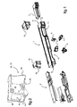
- a reinforcement beam 1 of a vehicle interior is organized for the circulation through air from a heating system, ventilation and / or air conditioning of the vehicle. More particularly, this beam 1 is arranged to accommodate at least one box 2.3 forming a selective air distribution module, or 4.5 even distributors, such as shutters or the like it receives via turntables linkage 6.7.
- This beam 1 is longitudinally extended in a constant direction and is open at its ends to provide windows 8, 9 through which are introduced caissons 2,3 for mounting inside the beam 1.
- the orientation of these windows 8,9 relative to the general axis A of extension of the beam 1 is such that it allows the passage of the caissons 2,3 through the windows 8,9 along this axis A extension of the beam 1. It will also be noted that the introduction of the caissons 2, 3 by the ends of the beam 1 is made possible for caissons 2, 3 which are longitudinally extended in a consistent manner, thanks to the constancy of the extension of the beam 1 between its ends.
- the section of the beam 1 is generally rectangular.
- the cross-section of the beam 1 is capable of varying, both in conformation and dimension, without necessarily inducing a variation in its general direction of extension, in particular for forming narrows 10, 11 for the passage of a column of direction of the vehicle or airbag.
- the ends of the beam 1 are equipped with end pieces 12, 13 for reinforcing and fixing the beam 1 on a supporting structure of the passenger compartment of the vehicle, and in particular on studs that it involves.
- These tips 12, 13 are each generally shaped in a couple of brackets 14,15 connected to each other by their free edges.
- a plate 16 closing the ends of the beam 1 is disposed at the end of the brackets 14,15 of each of the end pieces 12,13, and comprises centering members 17 on the outer faces of the beam 1.
- a wing 18 for fixing the 12.13 end caps on the carrier structure of the passenger compartment is provided on the rear face of this plate 16.
- the beam 1 has on its faces various mouths. Note that the architecture of the beam 1 proposed by the invention allows to relatively freely position these mouths along the sides of the beam, to adapt the latter to any vehicle without significantly altering its structure, nor affect to its intrinsic qualities of mechanical strength sought.
- an air intake opening 21 is formed substantially in the median zone of the lower face 22 of the beam 1.
- This air intake opening 21 is indicative of a dimension having a area between 1.2 dm2 and 2.2 dm2. It should be noted that such an area is to be estimated with regard to current values in the field for airflows of the order of 500 kg / h to 700 kg / h. Such a dimension is likely to be used for the introduction of at least one distributor 4.5 after introduction of the caissons 2,3 component of the air distribution module in particular. It will be noted at this stage of the description that the area of the vents of the beam, taken individually, is between 0.17 times and 0.15 times the area of the inlet mouth 21. air.
- the beam is characterized in that the area of the air outlet mouths 23, 24, 26, taken individually, is between 0.17 times and 0.25 times the area of the air inlet mouth 21 .
- Evacuation mouths 23 for right and left rear aeration respectively are provided at the corresponding ends of the lower face 22 of the beam 1.
- vents 24 for venting the lateral respectively right and left side are provided at the corresponding ends of the end face 25 of the beam 1.
- Evacuation vents 26 for central ventilation are provided in the central zone of the front face 25 of the beam 1.
- vents 27 for defogging respectively right and left are formed at the corresponding ends of the upper face 28 of the beam 1.
- These mouths 27 are each of an area between 0.05 and 0.2 times the cumulative area of vents 27, 29 of exhaust air for defrosting and / or soft diffusion 29 and for defogging 27.
- Evacuation and / or gentle diffusion vents 29 are provided in the median zone of the rear face 30 of the beam 1.
- These mouths 29 have a cumulative surface area of the order of between 0.8 and 0. , 95 times the cumulative area of vents 27,29 of air evacuation for defrosting and / or soft diffusion (29) and for defogging (27).
- the beam 1 has an outer section of the order of 1.81 dm2 and a maximum inner section of the order of 1.64 dm2, for a thickness of its faces of the order of 3 mm.
- the minimum inner section of the latter is of the order of 1 dm2.
- the cumulative area of the air outlet mouths 23,24,26,27,29 is of the order of 6.3 dm2 for respectively a distribution of these surfaces of the order of 0.962 dm2 for mouths 23 d. rear aeration, of the order of 0.956 dm2 for the vents 24 of lateral aeration, of the order of 0.814 dm2 for the vents 26 of central ventilation, of the order of 0.318 dm2 for defogger vents 27, and of the order of 1.438 dm2 for defrost vents 29 and / or soft diffusion.
- the cumulative area of mouths in the faces of the beam relative to the overall area of these mouths is of the order of 44% for the lower face of the beam, of the order of 28% for the front face, of the order of 5% for the upper face and of the order of 23% for the rear face.
- the internal section of the beam 1 to the right of the tapered 10,11 is in particular between 0.25 times and 0.7 times the area of the air inlet mouth. More specifically, in the case of the presence of a lateral vent 24 alone, the section of the beam 1 to the right of the constriction 10,11 is of the order of 0.25 times the area of the mouth of air intake 21, while in the case where this lateral ventilation mouth 24 is associated with other evacuation mouths, such as rear aeration 23 and lateral demister 27, this section of the beam 1 is of the order of 0.7 times the area of the air inlet. It will be understood that these dimensions of beam section are given as an indication, and must where appropriate take into account the size of an air distribution box or the like disposed within the beam.
- the sum of the areas of the vents 27,29 for evacuation and defrost discharge is between 0.7 dm2 and 1.6 dm2. It will be understood that these dimensions are to be taken into account with regard to a usual air flow rate in the range of 320 kg / h to 500 kg / h.
Landscapes
- Engineering & Computer Science (AREA)
- Mechanical Engineering (AREA)
- Physics & Mathematics (AREA)
- Thermal Sciences (AREA)
- Chemical & Material Sciences (AREA)
- Combustion & Propulsion (AREA)
- Transportation (AREA)
- Body Structure For Vehicles (AREA)
- Air-Conditioning For Vehicles (AREA)
- Duct Arrangements (AREA)
Applications Claiming Priority (1)
| Application Number | Priority Date | Filing Date | Title |
|---|---|---|---|
| FR0407560A FR2872742B1 (fr) | 2004-07-07 | 2004-07-07 | Poutre de renfort d'un habitacle organisee pour la reception d'un module de distribution selective d'air d'une installation de chauffage, de ventilation et/ou de climatisation |
Publications (3)
| Publication Number | Publication Date |
|---|---|
| EP1614563A2 true EP1614563A2 (de) | 2006-01-11 |
| EP1614563A3 EP1614563A3 (de) | 2006-05-17 |
| EP1614563B1 EP1614563B1 (de) | 2008-03-26 |
Family
ID=34940141
Family Applications (1)
| Application Number | Title | Priority Date | Filing Date |
|---|---|---|---|
| EP05105101A Expired - Lifetime EP1614563B1 (de) | 2004-07-07 | 2005-06-10 | Träger im Fahrzeuginnenraum für eine Luftversorgungseinrichtungeinheit einer Klima-Anlage. |
Country Status (7)
| Country | Link |
|---|---|
| US (1) | US7413243B2 (de) |
| EP (1) | EP1614563B1 (de) |
| JP (1) | JP2006021760A (de) |
| AT (1) | ATE390307T1 (de) |
| DE (1) | DE602005005561T2 (de) |
| ES (1) | ES2303186T3 (de) |
| FR (1) | FR2872742B1 (de) |
Cited By (1)
| Publication number | Priority date | Publication date | Assignee | Title |
|---|---|---|---|---|
| FR2936751A1 (fr) * | 2008-10-02 | 2010-04-09 | Valeo Vision Sas | Projecteur pour vehicule automobile monte sur une poutre de renfort logeant un canal de circulation d'air. |
Families Citing this family (7)
| Publication number | Priority date | Publication date | Assignee | Title |
|---|---|---|---|---|
| US20100274667A1 (en) * | 2009-04-24 | 2010-10-28 | Nexidia Inc. | Multimedia access |
| US20110215614A1 (en) * | 2010-02-25 | 2011-09-08 | Ayyakannu Mani | Lightweight cross-car beam and method of constructing a structural member |
| JP2016030559A (ja) * | 2014-07-30 | 2016-03-07 | ヤンマー株式会社 | 作業車両 |
| US10766339B2 (en) * | 2017-01-26 | 2020-09-08 | Ford Global Technologies, Llc | Vehicle structural air duct |
| JP6958388B2 (ja) * | 2018-01-27 | 2021-11-02 | マツダ株式会社 | 車両用空調装置 |
| CN108482072B (zh) * | 2018-03-08 | 2020-09-29 | 潍柴动力股份有限公司 | 一种平台化风道 |
| CN115158488B (zh) * | 2022-06-27 | 2023-11-14 | 重庆长安汽车股份有限公司 | 一种集成通风管道的座椅安装梁总成及汽车 |
Citations (5)
| Publication number | Priority date | Publication date | Assignee | Title |
|---|---|---|---|---|
| DE4239171C1 (de) | 1992-11-21 | 1993-10-14 | Daimler Benz Ag | Der Luftzuführung dienender Querträger |
| WO1998049024A1 (en) | 1997-04-29 | 1998-11-05 | Volvo Personvagnar Ab | Arrangement for vehicle body structure |
| EP0989004A2 (de) | 1998-08-28 | 2000-03-29 | Delphi Technologies, Inc. | Kompaktes Modul einer Kraftfahrzeug-Klimaanlage |
| FR2799413A1 (fr) | 1999-10-06 | 2001-04-13 | Valeo Climatisation | Installation de chauffage et/ou climatisation pour vehicule automobile, comportant un systeme de distribution d'air |
| WO2001068391A2 (en) | 2000-03-17 | 2001-09-20 | Magna Interior Systems, Inc. | A dashboard car duct with integrated mode doors and hvac module |
Family Cites Families (17)
| Publication number | Priority date | Publication date | Assignee | Title |
|---|---|---|---|---|
| DE4232847A1 (de) * | 1992-09-30 | 1994-03-31 | Audi Ag | Armaturenbrett für ein Kraftfahrzeug |
| US5934744A (en) * | 1997-10-01 | 1999-08-10 | General Motors Corporation | Cross car structural beam |
| DE19926636A1 (de) * | 1999-06-11 | 2000-12-14 | Porsche Ag | Cockpitquerträger in einem Kraftfahrzeug |
| JP2001246922A (ja) * | 2000-03-06 | 2001-09-11 | Unipres Corp | 自動車用空調ダクト付クロスメンバ |
| ATE271488T1 (de) * | 2000-09-07 | 2004-08-15 | Behr Gmbh & Co | Bauteil für ein kraftfahrzeug |
| DE10045347A1 (de) * | 2000-09-14 | 2002-03-28 | Behr Gmbh & Co | Anordnung eines Gehäuses einer Heizungs- und/oder Klimaanlage |
| FR2834271B1 (fr) * | 2001-12-27 | 2004-02-20 | Sai Automotive Allibert Ind | Ensemble structurel de planche de bord et procede pour le realiser |
| US6644722B2 (en) * | 2002-01-17 | 2003-11-11 | Bayer Corporation | Molded article having a rigid support and a rigid hollow member |
| JP4239594B2 (ja) * | 2002-04-10 | 2009-03-18 | 株式会社デンソー | 車両用空調ダクト構造 |
| FR2841506B1 (fr) * | 2002-06-26 | 2004-08-27 | Faurecia Interieur Ind | Ensemble de planche de bord et vehicule comprenant l'ensemble |
| US6912863B2 (en) * | 2002-08-30 | 2005-07-05 | Denso Corporation | Cooling structure for cooling vehicle electronic unit |
| EP1415897B1 (de) * | 2002-11-01 | 2006-12-13 | Calsonic Kansei Corporation | Querträger und Herstellungsverfahren |
| US7128360B2 (en) * | 2002-12-10 | 2006-10-31 | Delphi Technologies, Inc. | Structural hybrid attachment system and method |
| US20040108744A1 (en) * | 2002-12-10 | 2004-06-10 | Scheib Chales J. | Structural hybrid attachment system |
| US6688680B1 (en) * | 2002-12-17 | 2004-02-10 | Bayer Polymers Llc | Molded cross vehicle beam |
| JP2004203244A (ja) * | 2002-12-25 | 2004-07-22 | Collins & Aikman Corp | デフロスタノズル |
| US7264295B2 (en) * | 2005-07-26 | 2007-09-04 | Visteon Global Technologies, Inc. | Vehicle cockpit attachment structure with integrated plastic composite functional molded features |
-
2004
- 2004-07-07 FR FR0407560A patent/FR2872742B1/fr not_active Expired - Lifetime
-
2005
- 2005-06-10 DE DE602005005561T patent/DE602005005561T2/de not_active Expired - Lifetime
- 2005-06-10 AT AT05105101T patent/ATE390307T1/de not_active IP Right Cessation
- 2005-06-10 EP EP05105101A patent/EP1614563B1/de not_active Expired - Lifetime
- 2005-06-10 ES ES05105101T patent/ES2303186T3/es not_active Expired - Lifetime
- 2005-07-06 US US11/175,496 patent/US7413243B2/en not_active Expired - Lifetime
- 2005-07-06 JP JP2005197471A patent/JP2006021760A/ja active Pending
Patent Citations (5)
| Publication number | Priority date | Publication date | Assignee | Title |
|---|---|---|---|---|
| DE4239171C1 (de) | 1992-11-21 | 1993-10-14 | Daimler Benz Ag | Der Luftzuführung dienender Querträger |
| WO1998049024A1 (en) | 1997-04-29 | 1998-11-05 | Volvo Personvagnar Ab | Arrangement for vehicle body structure |
| EP0989004A2 (de) | 1998-08-28 | 2000-03-29 | Delphi Technologies, Inc. | Kompaktes Modul einer Kraftfahrzeug-Klimaanlage |
| FR2799413A1 (fr) | 1999-10-06 | 2001-04-13 | Valeo Climatisation | Installation de chauffage et/ou climatisation pour vehicule automobile, comportant un systeme de distribution d'air |
| WO2001068391A2 (en) | 2000-03-17 | 2001-09-20 | Magna Interior Systems, Inc. | A dashboard car duct with integrated mode doors and hvac module |
Cited By (1)
| Publication number | Priority date | Publication date | Assignee | Title |
|---|---|---|---|---|
| FR2936751A1 (fr) * | 2008-10-02 | 2010-04-09 | Valeo Vision Sas | Projecteur pour vehicule automobile monte sur une poutre de renfort logeant un canal de circulation d'air. |
Also Published As
| Publication number | Publication date |
|---|---|
| DE602005005561D1 (de) | 2008-05-08 |
| FR2872742B1 (fr) | 2008-12-05 |
| FR2872742A1 (fr) | 2006-01-13 |
| US20060199491A1 (en) | 2006-09-07 |
| ATE390307T1 (de) | 2008-04-15 |
| EP1614563A3 (de) | 2006-05-17 |
| JP2006021760A (ja) | 2006-01-26 |
| ES2303186T3 (es) | 2008-08-01 |
| DE602005005561T2 (de) | 2009-04-30 |
| US7413243B2 (en) | 2008-08-19 |
| EP1614563B1 (de) | 2008-03-26 |
Similar Documents
| Publication | Publication Date | Title |
|---|---|---|
| CA2674264C (fr) | Section de fuselage pour aeronef et aeronef comprenant une telle section | |
| CA2661123C (fr) | Assemblage de panneaux et procede de montage d'un assemblage de panneaux | |
| EP1614563B1 (de) | Träger im Fahrzeuginnenraum für eine Luftversorgungseinrichtungeinheit einer Klima-Anlage. | |
| FR2928715A1 (fr) | Procede d'assemblage de panneaux bord a bord | |
| FR3055612A1 (fr) | Structure compartimentee pour le traitement acoustique et le degivrage d'une nacelle d'aeronef et nacelle d'aeronef incorporant ladite structure | |
| FR2460823A1 (fr) | Revetement interne destine au plafond de vehicules, notamment ferroviaires | |
| FR2772682A1 (fr) | Poste de conduite modulaire pour vehicule | |
| FR3059625B1 (fr) | Cloison de fixation d'au moins un element fonctionnel et vehicule comprenant une telle cloison | |
| EP2977287A1 (de) | Paneel für die ausbildung eines schienenfahrzeugkastens und verfahren zur herstellung desselben | |
| EP1580098A1 (de) | Dach für Kraftfahrzeug, und Kraftfahrzeug mit einem derartigen Dach | |
| EP1614562B1 (de) | Luftweg und -Verteilung einer Klima-Einheit in einem Kraftfahrzeug. | |
| EP1630075B1 (de) | Fahrzeugkarosserie mit verbessertem dynamischen Verhalten | |
| FR2799412A1 (fr) | Installation de chauffage et/ou climatisation presentant un systeme de distribution d'air dans l'habitacle d'un vehicule automobile | |
| EP1195316B1 (de) | Armaturenträger für Kraftfahrzeug, und Kraftfahrzeug mit derartigen Armaturenträger | |
| FR2881708A1 (fr) | Poutre structurelle pour habitacle de vehicule, logeant des organes aerauliques de distribution selective d'air | |
| EP1470990B1 (de) | Armaturenbrett für Kraftfahrzeug | |
| EP1044849B1 (de) | Befestigungselement aus geformtem Kunststoff für Automobilbau | |
| FR3021944A1 (fr) | Partie avant de la structure d'un vehicule automobile | |
| EP4541633A1 (de) | Instrumententafel und kraftfahrzeug mit einer solchen instrumententafel | |
| FR2831511A1 (fr) | Cabine de vehicule realisee par assemblage de troncon de profile | |
| EP3409558B1 (de) | Luftverteilungskanal für belüftungssystem, insbesondere für schienenfahrzeug | |
| EP1806272A1 (de) | Vorrichtung zum Schutz eines Einfüllstutzens eines Kraftstofftanks eines Kraftfahrzeugs | |
| FR3036357A1 (fr) | Systeme de conditionnement d'air pour vehicule de type ferroviaire | |
| EP1640196B1 (de) | Aufbauelement einer Kfz-Fahrgastzelle mit wählbarer Luftversorgung aufweisendes Modul | |
| EP3090925B1 (de) | Querträger einer fensteröffnung eines kraftfahrzeugs, und dazugehöriges kraftfahrzeug |
Legal Events
| Date | Code | Title | Description |
|---|---|---|---|
| PUAI | Public reference made under article 153(3) epc to a published international application that has entered the european phase |
Free format text: ORIGINAL CODE: 0009012 |
|
| AK | Designated contracting states |
Kind code of ref document: A2 Designated state(s): AT BE BG CH CY CZ DE DK EE ES FI FR GB GR HU IE IS IT LI LT LU MC NL PL PT RO SE SI SK TR |
|
| AX | Request for extension of the european patent |
Extension state: AL BA HR LV MK YU |
|
| PUAL | Search report despatched |
Free format text: ORIGINAL CODE: 0009013 |
|
| AK | Designated contracting states |
Kind code of ref document: A3 Designated state(s): AT BE BG CH CY CZ DE DK EE ES FI FR GB GR HU IE IS IT LI LT LU MC NL PL PT RO SE SI SK TR |
|
| AX | Request for extension of the european patent |
Extension state: AL BA HR LV MK YU |
|
| RIC1 | Information provided on ipc code assigned before grant |
Ipc: B62D 25/14 20060101ALI20060328BHEP Ipc: B60H 1/00 20060101AFI20050929BHEP |
|
| 17P | Request for examination filed |
Effective date: 20060915 |
|
| AKX | Designation fees paid |
Designated state(s): AT BE BG CH CY CZ DE DK EE ES FI FR GB GR HU IE IS IT LI LT LU MC NL PL PT RO SE SI SK TR |
|
| 17Q | First examination report despatched |
Effective date: 20070219 |
|
| GRAP | Despatch of communication of intention to grant a patent |
Free format text: ORIGINAL CODE: EPIDOSNIGR1 |
|
| GRAS | Grant fee paid |
Free format text: ORIGINAL CODE: EPIDOSNIGR3 |
|
| GRAA | (expected) grant |
Free format text: ORIGINAL CODE: 0009210 |
|
| AK | Designated contracting states |
Kind code of ref document: B1 Designated state(s): AT BE BG CH CY CZ DE DK EE ES FI FR GB GR HU IE IS IT LI LT LU MC NL PL PT RO SE SI SK TR |
|
| REG | Reference to a national code |
Ref country code: GB Ref legal event code: FG4D Free format text: NOT ENGLISH |
|
| REG | Reference to a national code |
Ref country code: CH Ref legal event code: EP Ref country code: IE Ref legal event code: FG4D Free format text: LANGUAGE OF EP DOCUMENT: FRENCH |
|
| REF | Corresponds to: |
Ref document number: 602005005561 Country of ref document: DE Date of ref document: 20080508 Kind code of ref document: P |
|
| PG25 | Lapsed in a contracting state [announced via postgrant information from national office to epo] |
Ref country code: FI Free format text: LAPSE BECAUSE OF FAILURE TO SUBMIT A TRANSLATION OF THE DESCRIPTION OR TO PAY THE FEE WITHIN THE PRESCRIBED TIME-LIMIT Effective date: 20080326 |
|
| REG | Reference to a national code |
Ref country code: ES Ref legal event code: FG2A Ref document number: 2303186 Country of ref document: ES Kind code of ref document: T3 |
|
| PG25 | Lapsed in a contracting state [announced via postgrant information from national office to epo] |
Ref country code: AT Free format text: LAPSE BECAUSE OF FAILURE TO SUBMIT A TRANSLATION OF THE DESCRIPTION OR TO PAY THE FEE WITHIN THE PRESCRIBED TIME-LIMIT Effective date: 20080326 |
|
| NLV1 | Nl: lapsed or annulled due to failure to fulfill the requirements of art. 29p and 29m of the patents act | ||
| PG25 | Lapsed in a contracting state [announced via postgrant information from national office to epo] |
Ref country code: SI Free format text: LAPSE BECAUSE OF FAILURE TO SUBMIT A TRANSLATION OF THE DESCRIPTION OR TO PAY THE FEE WITHIN THE PRESCRIBED TIME-LIMIT Effective date: 20080326 Ref country code: PL Free format text: LAPSE BECAUSE OF FAILURE TO SUBMIT A TRANSLATION OF THE DESCRIPTION OR TO PAY THE FEE WITHIN THE PRESCRIBED TIME-LIMIT Effective date: 20080326 |
|
| REG | Reference to a national code |
Ref country code: IE Ref legal event code: FD4D |
|
| PG25 | Lapsed in a contracting state [announced via postgrant information from national office to epo] |
Ref country code: SK Free format text: LAPSE BECAUSE OF FAILURE TO SUBMIT A TRANSLATION OF THE DESCRIPTION OR TO PAY THE FEE WITHIN THE PRESCRIBED TIME-LIMIT Effective date: 20080326 Ref country code: SE Free format text: LAPSE BECAUSE OF FAILURE TO SUBMIT A TRANSLATION OF THE DESCRIPTION OR TO PAY THE FEE WITHIN THE PRESCRIBED TIME-LIMIT Effective date: 20080626 Ref country code: PT Free format text: LAPSE BECAUSE OF FAILURE TO SUBMIT A TRANSLATION OF THE DESCRIPTION OR TO PAY THE FEE WITHIN THE PRESCRIBED TIME-LIMIT Effective date: 20080901 |
|
| PG25 | Lapsed in a contracting state [announced via postgrant information from national office to epo] |
Ref country code: NL Free format text: LAPSE BECAUSE OF FAILURE TO SUBMIT A TRANSLATION OF THE DESCRIPTION OR TO PAY THE FEE WITHIN THE PRESCRIBED TIME-LIMIT Effective date: 20080326 Ref country code: RO Free format text: LAPSE BECAUSE OF FAILURE TO SUBMIT A TRANSLATION OF THE DESCRIPTION OR TO PAY THE FEE WITHIN THE PRESCRIBED TIME-LIMIT Effective date: 20080326 |
|
| BERE | Be: lapsed |
Owner name: VALEO SYSTEMES THERMIQUES Effective date: 20080630 |
|
| PG25 | Lapsed in a contracting state [announced via postgrant information from national office to epo] |
Ref country code: IS Free format text: LAPSE BECAUSE OF FAILURE TO SUBMIT A TRANSLATION OF THE DESCRIPTION OR TO PAY THE FEE WITHIN THE PRESCRIBED TIME-LIMIT Effective date: 20080726 |
|
| PG25 | Lapsed in a contracting state [announced via postgrant information from national office to epo] |
Ref country code: LT Free format text: LAPSE BECAUSE OF FAILURE TO SUBMIT A TRANSLATION OF THE DESCRIPTION OR TO PAY THE FEE WITHIN THE PRESCRIBED TIME-LIMIT Effective date: 20080326 Ref country code: MC Free format text: LAPSE BECAUSE OF NON-PAYMENT OF DUE FEES Effective date: 20080630 Ref country code: IE Free format text: LAPSE BECAUSE OF FAILURE TO SUBMIT A TRANSLATION OF THE DESCRIPTION OR TO PAY THE FEE WITHIN THE PRESCRIBED TIME-LIMIT Effective date: 20080326 Ref country code: DK Free format text: LAPSE BECAUSE OF FAILURE TO SUBMIT A TRANSLATION OF THE DESCRIPTION OR TO PAY THE FEE WITHIN THE PRESCRIBED TIME-LIMIT Effective date: 20080326 |
|
| PLBE | No opposition filed within time limit |
Free format text: ORIGINAL CODE: 0009261 |
|
| STAA | Information on the status of an ep patent application or granted ep patent |
Free format text: STATUS: NO OPPOSITION FILED WITHIN TIME LIMIT |
|
| 26N | No opposition filed |
Effective date: 20081230 |
|
| PG25 | Lapsed in a contracting state [announced via postgrant information from national office to epo] |
Ref country code: BE Free format text: LAPSE BECAUSE OF NON-PAYMENT OF DUE FEES Effective date: 20080630 |
|
| PG25 | Lapsed in a contracting state [announced via postgrant information from national office to epo] |
Ref country code: EE Free format text: LAPSE BECAUSE OF FAILURE TO SUBMIT A TRANSLATION OF THE DESCRIPTION OR TO PAY THE FEE WITHIN THE PRESCRIBED TIME-LIMIT Effective date: 20080326 Ref country code: BG Free format text: LAPSE BECAUSE OF FAILURE TO SUBMIT A TRANSLATION OF THE DESCRIPTION OR TO PAY THE FEE WITHIN THE PRESCRIBED TIME-LIMIT Effective date: 20080626 |
|
| PG25 | Lapsed in a contracting state [announced via postgrant information from national office to epo] |
Ref country code: CY Free format text: LAPSE BECAUSE OF FAILURE TO SUBMIT A TRANSLATION OF THE DESCRIPTION OR TO PAY THE FEE WITHIN THE PRESCRIBED TIME-LIMIT Effective date: 20080326 |
|
| REG | Reference to a national code |
Ref country code: CH Ref legal event code: PL |
|
| GBPC | Gb: european patent ceased through non-payment of renewal fee |
Effective date: 20090610 |
|
| PG25 | Lapsed in a contracting state [announced via postgrant information from national office to epo] |
Ref country code: CH Free format text: LAPSE BECAUSE OF NON-PAYMENT OF DUE FEES Effective date: 20090630 Ref country code: LI Free format text: LAPSE BECAUSE OF NON-PAYMENT OF DUE FEES Effective date: 20090630 |
|
| PG25 | Lapsed in a contracting state [announced via postgrant information from national office to epo] |
Ref country code: GB Free format text: LAPSE BECAUSE OF NON-PAYMENT OF DUE FEES Effective date: 20090610 |
|
| PG25 | Lapsed in a contracting state [announced via postgrant information from national office to epo] |
Ref country code: LU Free format text: LAPSE BECAUSE OF NON-PAYMENT OF DUE FEES Effective date: 20080610 Ref country code: HU Free format text: LAPSE BECAUSE OF FAILURE TO SUBMIT A TRANSLATION OF THE DESCRIPTION OR TO PAY THE FEE WITHIN THE PRESCRIBED TIME-LIMIT Effective date: 20080927 |
|
| PG25 | Lapsed in a contracting state [announced via postgrant information from national office to epo] |
Ref country code: TR Free format text: LAPSE BECAUSE OF FAILURE TO SUBMIT A TRANSLATION OF THE DESCRIPTION OR TO PAY THE FEE WITHIN THE PRESCRIBED TIME-LIMIT Effective date: 20080326 |
|
| PG25 | Lapsed in a contracting state [announced via postgrant information from national office to epo] |
Ref country code: GR Free format text: LAPSE BECAUSE OF FAILURE TO SUBMIT A TRANSLATION OF THE DESCRIPTION OR TO PAY THE FEE WITHIN THE PRESCRIBED TIME-LIMIT Effective date: 20080627 |
|
| REG | Reference to a national code |
Ref country code: FR Ref legal event code: PLFP Year of fee payment: 12 |
|
| REG | Reference to a national code |
Ref country code: FR Ref legal event code: PLFP Year of fee payment: 13 |
|
| PGFP | Annual fee paid to national office [announced via postgrant information from national office to epo] |
Ref country code: CZ Payment date: 20170522 Year of fee payment: 13 Ref country code: FR Payment date: 20170630 Year of fee payment: 13 Ref country code: DE Payment date: 20170614 Year of fee payment: 13 |
|
| PGFP | Annual fee paid to national office [announced via postgrant information from national office to epo] |
Ref country code: IT Payment date: 20170619 Year of fee payment: 13 |
|
| PGFP | Annual fee paid to national office [announced via postgrant information from national office to epo] |
Ref country code: ES Payment date: 20170707 Year of fee payment: 13 |
|
| REG | Reference to a national code |
Ref country code: DE Ref legal event code: R119 Ref document number: 602005005561 Country of ref document: DE |
|
| PG25 | Lapsed in a contracting state [announced via postgrant information from national office to epo] |
Ref country code: CZ Free format text: LAPSE BECAUSE OF NON-PAYMENT OF DUE FEES Effective date: 20180610 |
|
| PG25 | Lapsed in a contracting state [announced via postgrant information from national office to epo] |
Ref country code: FR Free format text: LAPSE BECAUSE OF NON-PAYMENT OF DUE FEES Effective date: 20180630 Ref country code: DE Free format text: LAPSE BECAUSE OF NON-PAYMENT OF DUE FEES Effective date: 20190101 Ref country code: IT Free format text: LAPSE BECAUSE OF NON-PAYMENT OF DUE FEES Effective date: 20180610 |
|
| REG | Reference to a national code |
Ref country code: ES Ref legal event code: FD2A Effective date: 20190916 |
|
| PG25 | Lapsed in a contracting state [announced via postgrant information from national office to epo] |
Ref country code: ES Free format text: LAPSE BECAUSE OF NON-PAYMENT OF DUE FEES Effective date: 20180611 |