EP1614908A2 - Vérin avec course réglable - Google Patents
Vérin avec course réglable Download PDFInfo
- Publication number
- EP1614908A2 EP1614908A2 EP05105896A EP05105896A EP1614908A2 EP 1614908 A2 EP1614908 A2 EP 1614908A2 EP 05105896 A EP05105896 A EP 05105896A EP 05105896 A EP05105896 A EP 05105896A EP 1614908 A2 EP1614908 A2 EP 1614908A2
- Authority
- EP
- European Patent Office
- Prior art keywords
- pin
- cylinder
- actuator according
- actuator
- driving shaft
- Prior art date
- Legal status (The legal status is an assumption and is not a legal conclusion. Google has not performed a legal analysis and makes no representation as to the accuracy of the status listed.)
- Granted
Links
- 238000007789 sealing Methods 0.000 claims description 3
- 230000037431 insertion Effects 0.000 claims description 2
- 238000003780 insertion Methods 0.000 claims description 2
- 230000003213 activating effect Effects 0.000 description 2
- 230000004913 activation Effects 0.000 description 1
- 230000004888 barrier function Effects 0.000 description 1
Images


Classifications
-
- F—MECHANICAL ENGINEERING; LIGHTING; HEATING; WEAPONS; BLASTING
- F15—FLUID-PRESSURE ACTUATORS; HYDRAULICS OR PNEUMATICS IN GENERAL
- F15B—SYSTEMS ACTING BY MEANS OF FLUIDS IN GENERAL; FLUID-PRESSURE ACTUATORS, e.g. SERVOMOTORS; DETAILS OF FLUID-PRESSURE SYSTEMS, NOT OTHERWISE PROVIDED FOR
- F15B15/00—Fluid-actuated devices for displacing a member from one position to another; Gearing associated therewith
- F15B15/20—Other details, e.g. assembly with regulating devices
- F15B15/26—Locking mechanisms
- F15B15/261—Locking mechanisms using positive interengagement, e.g. balls and grooves, for locking in the end positions
-
- F—MECHANICAL ENGINEERING; LIGHTING; HEATING; WEAPONS; BLASTING
- F15—FLUID-PRESSURE ACTUATORS; HYDRAULICS OR PNEUMATICS IN GENERAL
- F15B—SYSTEMS ACTING BY MEANS OF FLUIDS IN GENERAL; FLUID-PRESSURE ACTUATORS, e.g. SERVOMOTORS; DETAILS OF FLUID-PRESSURE SYSTEMS, NOT OTHERWISE PROVIDED FOR
- F15B15/00—Fluid-actuated devices for displacing a member from one position to another; Gearing associated therewith
- F15B15/20—Other details, e.g. assembly with regulating devices
- F15B15/24—Other details, e.g. assembly with regulating devices for restricting the stroke
Definitions
- the present invention relates to a pneumatic and/or hydraulic actuator.
- the present invention relates to a hydraulic actuator which can be used for activating sensors, valves, etc... in industrial plants.
- the run of the shaft substantially corresponds to the run of the piston and exclusively creates two pre-established positions in the project phase of said type of actuator.
- the Applicant considered the possibility of varying the run of the driving shaft of an actuator operating with air/oil, in relation to the possible applications which the actuator itself can have.
- the Applicant has produced an actuator in which the run of a driving shaft, which is pneumatically operated by a piston, can vary on the basis of the insertion in the body of the actuator of at least one cylinder, so that the body of said cylinder forms a barrier along the run of the driving shaft causing the stoppage of the shaft itself.
- a series of differentiated runs of the driving shaft, pre-selected by the pneumatic and/or hydraulic activation of said cylinders, are produced by the presence of one or more housings, situated along the body of the actuator, in which each cylinder can be inserted.
- An aspect of the present invention relates to a pneumatic/hydraulic actuator comprising a container body, a driving shaft, inserted in a cylindrical housing or pass-through hole of said container body, said driving shaft being mobile along a longitudinal axis of the actuator and which can be hydraulically operated, characterized in that it comprises at least one pass-through hole situated on said container body which is substantially orthogonal to said moving axis of the shaft in which a cylinder is integrated, which can operate in such a way as to intercept the run of the driving shaft, creating a pre-established run thereof along said longitudinal axis.
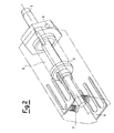
- the hydraulic actuator comprises a container body 2 which has a substantially parallelepiped form and a driving shaft 3 inserted in a cylindrical housing or pass-through hole of said container body. Said driving shaft is moveable along a longitudinal axis Y of the actuator.
- the container body can be equivalently produced in a cylindrical, hexagonal, octagonal or more generally polyhedral form.
- a hydraulic/pneumatic piston is situated inside said container body, which causes the movement of said driving shaft 3, comprising a sealing ring 4 integral with said shaft which moves in a suitable housing 5, preferably cylindrical, positioned inside the container body 2.
- the cylindrical housing is filled, in a conventional manner, with compressed air by means of an intake socket 6 for the introduction of compressed air into the actuator and, the air is expelled from this housing by means of an outlet socket (not illustrated).
- a pass-through hole 6 On the container body of said actuator, there is at least one pass-through hole 6, which is substantially orthogonal to said movement axis of the shaft in which a hydraulically operated cylinder 7 is integrated, which intercepts the run of the shaft, for example by means of the ring 5 creating a run-end for the movement of the driving shaft.
- a series of pass-through holes situated along the container body, in each of which a cylinder 7 is integrated, so that by selectively activating each cylinder, a series of differentiated runs of the driving shaft of the actuator can be effected.
- the container body is parallelepiped or hexagonal, or generally has a form characterized by flat side surfaces
- said pass-through holes for the cylinders can be advantageously situated on more than one of the surfaces so as to increase the possibility of having various differentiated runs of the driving shaft.
- Said cylinder preferably comprises a corresponding ring 71, suitable for creating an inlet for a tub (not shown) of compressed air, a pin 72 which slides inside said cylinder, having a head 721 which acts as a thrust surface for the compressed air introduced into the cylinder from said tube.
- the leg 722 of the pin is in contact with the ring 5 causing the stoppage of the movement of the driving shaft.
- said element in the lower part of the pin 72, there is a corresponding element suitable for contrasting the upper thrust of compressed air.
- said element consists of a spring 74.
- said corresponding element can be obtained by inserting pressurized air also in the lower part of the cylinder below the head of the pin, thus creating a chamber containing pressurized air; in this case, the pin moves in the cylinder on the basis of a pressure differential between the upper and lower part of the pin itself.
- the movement of the pin can be obtained by means of a magnetic drive and/or electric drive.
- All the cylinders can be constrained in the pass-through holes by means of at least one stoppage fork 9 which is inserted longitudinally.
Landscapes
- Engineering & Computer Science (AREA)
- Physics & Mathematics (AREA)
- Fluid Mechanics (AREA)
- Mechanical Engineering (AREA)
- General Engineering & Computer Science (AREA)
- Actuator (AREA)
Applications Claiming Priority (1)
| Application Number | Priority Date | Filing Date | Title |
|---|---|---|---|
| IT001343A ITMI20041343A1 (it) | 2004-07-05 | 2004-07-05 | Attuatore a corsa variabile |
Publications (3)
| Publication Number | Publication Date |
|---|---|
| EP1614908A2 true EP1614908A2 (fr) | 2006-01-11 |
| EP1614908A3 EP1614908A3 (fr) | 2007-06-13 |
| EP1614908B1 EP1614908B1 (fr) | 2010-10-27 |
Family
ID=34940258
Family Applications (1)
| Application Number | Title | Priority Date | Filing Date |
|---|---|---|---|
| EP05105896A Expired - Fee Related EP1614908B1 (fr) | 2004-07-05 | 2005-06-30 | Vérin avec course réglable |
Country Status (6)
| Country | Link |
|---|---|
| US (1) | US7240605B2 (fr) |
| EP (1) | EP1614908B1 (fr) |
| JP (1) | JP2006022956A (fr) |
| CN (1) | CN1721712A (fr) |
| DE (1) | DE602005024343D1 (fr) |
| IT (1) | ITMI20041343A1 (fr) |
Cited By (1)
| Publication number | Priority date | Publication date | Assignee | Title |
|---|---|---|---|---|
| EP2628577A1 (fr) * | 2012-02-14 | 2013-08-21 | Heidelberger Druckmaschinen AG | Dispositif de remplacement de l'outil supérieur d'une estampilleuse |
Families Citing this family (7)
| Publication number | Priority date | Publication date | Assignee | Title |
|---|---|---|---|---|
| GB0810391D0 (en) * | 2008-06-06 | 2008-07-09 | Isentropic Ltd | Fluid servo and applications |
| US9500099B2 (en) * | 2012-07-02 | 2016-11-22 | United Techologies Corporation | Cover plate for a component of a gas turbine engine |
| TWI485821B (zh) | 2014-02-24 | 2015-05-21 | 新東亞微電子股份有限公司 | 指紋辨識晶片封裝模組及其製造方法 |
| DE102014205986B4 (de) | 2014-03-31 | 2021-03-18 | MTU Aero Engines AG | Leitschaufelkranz und Strömungsmaschine |
| CN105417176B (zh) * | 2015-11-18 | 2018-07-31 | 江苏长江药业有限公司 | 一种包衣造粒机用进/出料阀 |
| US10815817B2 (en) * | 2016-01-21 | 2020-10-27 | Raytheon Technologies Corporation | Heat flux measurement system |
| ES2724908B2 (es) * | 2019-06-04 | 2020-06-04 | Actreg S A U | Dispositivo para prueba parcial de carrera, bloqueo y ajuste automatico de carrera en actuadores de valvulas de emergencia |
Citations (1)
| Publication number | Priority date | Publication date | Assignee | Title |
|---|---|---|---|---|
| US20020033606A1 (en) | 2000-05-02 | 2002-03-21 | Shinyo Kimoto | Cylinder, load port using it, and production system |
Family Cites Families (11)
| Publication number | Priority date | Publication date | Assignee | Title |
|---|---|---|---|---|
| US2118890A (en) * | 1936-11-27 | 1938-05-31 | Servo Frein Dewandre Sa | Control device with predetermined successive positions |
| US2689157A (en) * | 1952-12-09 | 1954-09-14 | Censo Edward A Di | Combined adjustable desk and easel |
| US3889576A (en) * | 1969-06-13 | 1975-06-17 | Sheffer Corp | Locking cylinder with improved locking structure |
| US3848515A (en) * | 1972-12-29 | 1974-11-19 | Ibm | Linear hydraulic drive system |
| FR2338827A1 (fr) * | 1976-01-26 | 1977-08-19 | Wabco Westinghouse | Cylindre de frein a ressort |
| DE2923238C2 (de) * | 1979-06-08 | 1981-06-04 | Josef 4815 Schloss Holte Fortmeier | Hybzylinder mit einer druckabhängigen Teilhubverriegelung für die Kolbenstange |
| US4524676A (en) * | 1984-01-19 | 1985-06-25 | American Standard Inc. | Hydraulic cylinder locking device |
| US4697680A (en) * | 1986-06-05 | 1987-10-06 | Sundstrand Corporation | Fluid operated disconnect coupling |
| US5048656A (en) * | 1990-08-29 | 1991-09-17 | Eaton Corporation | Fluid operated clutch control system having latch member |
| GB0301095D0 (en) * | 2003-01-17 | 2003-02-19 | Gibbs Tech Ltd | Actuator |
| DE10357555B4 (de) * | 2003-12-10 | 2007-05-24 | Rexroth Mecman Gmbh | Druckmittelzylinder mit verstellbarem Hub |
-
2004
- 2004-07-05 IT IT001343A patent/ITMI20041343A1/it unknown
-
2005
- 2005-06-30 EP EP05105896A patent/EP1614908B1/fr not_active Expired - Fee Related
- 2005-06-30 DE DE602005024343T patent/DE602005024343D1/de not_active Expired - Lifetime
- 2005-07-01 US US11/174,295 patent/US7240605B2/en not_active Expired - Fee Related
- 2005-07-05 JP JP2005196062A patent/JP2006022956A/ja not_active Withdrawn
- 2005-07-05 CN CN200510082028.5A patent/CN1721712A/zh active Pending
Patent Citations (1)
| Publication number | Priority date | Publication date | Assignee | Title |
|---|---|---|---|---|
| US20020033606A1 (en) | 2000-05-02 | 2002-03-21 | Shinyo Kimoto | Cylinder, load port using it, and production system |
Cited By (1)
| Publication number | Priority date | Publication date | Assignee | Title |
|---|---|---|---|---|
| EP2628577A1 (fr) * | 2012-02-14 | 2013-08-21 | Heidelberger Druckmaschinen AG | Dispositif de remplacement de l'outil supérieur d'une estampilleuse |
Also Published As
| Publication number | Publication date |
|---|---|
| EP1614908A3 (fr) | 2007-06-13 |
| DE602005024343D1 (de) | 2010-12-09 |
| US20060005696A1 (en) | 2006-01-12 |
| CN1721712A (zh) | 2006-01-18 |
| EP1614908B1 (fr) | 2010-10-27 |
| US7240605B2 (en) | 2007-07-10 |
| ITMI20041343A1 (it) | 2004-10-05 |
| JP2006022956A (ja) | 2006-01-26 |
Similar Documents
| Publication | Publication Date | Title |
|---|---|---|
| US5893707A (en) | Pneumatically shifted reciprocating pump | |
| CN101680467B (zh) | 具有磁制动装置的阀 | |
| US6394521B1 (en) | Gripper with enhanced gripping power accuracy and repeatability | |
| KR970009954B1 (ko) | 왕복운동가능 기계용 공기 밸브 액츄에이터 | |
| KR101479585B1 (ko) | 공압식 자체-조절 밸브 | |
| EP1614908A2 (fr) | Vérin avec course réglable | |
| EP2012012B1 (fr) | Dispositif à soupape et pompe à diaphragme actionné de manière pneumatique avec un tel dispositif | |
| EP1869325B1 (fr) | Machines a fluide | |
| CN206656012U (zh) | 阀以及用于与控制阀一起使用的运动转换装置 | |
| KR960705130A (ko) | 편심 왕복운동 장치(offset reciprocable device) | |
| RU2007124544A (ru) | Цилиндропоршневой узел с осевым приводом | |
| EP1188581B1 (fr) | Dispositif de soupape régulatrice dans un outil à fluide sous-pression | |
| US7284475B2 (en) | Pneumatic reciprocating motor | |
| JP7221236B2 (ja) | 磁石を含む往復流体ポンプ、ならびにこれに関連するアセンブリ、システム、および方法 | |
| JP3578652B2 (ja) | ポンプ装置 | |
| EP3899274B1 (fr) | Compresseur à piston | |
| JPH0749041Y2 (ja) | 流体圧駆動連続作動型往復動アクチュエータ | |
| KR100904864B1 (ko) | 밸브 구동용 액추에이터 | |
| KR20090001400U (ko) | 액추에이터 | |
| EP3377763B1 (fr) | Mécanisme d'entraînement alternatif présentant un évent de bobine | |
| RU48599U1 (ru) | Аксиально-поршневая гидромашина с датчиком положения поршня управления | |
| RU160538U1 (ru) | Свободнопоршневой пневматический вакуумный насос | |
| JPH02266104A (ja) | 流体圧駆動連続作動型往復動アクチュエータ | |
| JP2014126188A (ja) | パワーヘッド組立 | |
| JPH02261911A (ja) | 流体圧駆動連続作動型往復動アクチュエータ |
Legal Events
| Date | Code | Title | Description |
|---|---|---|---|
| PUAI | Public reference made under article 153(3) epc to a published international application that has entered the european phase |
Free format text: ORIGINAL CODE: 0009012 |
|
| AK | Designated contracting states |
Kind code of ref document: A2 Designated state(s): AT BE BG CH CY CZ DE DK EE ES FI FR GB GR HU IE IS IT LI LT LU MC NL PL PT RO SE SI SK TR |
|
| AX | Request for extension of the european patent |
Extension state: AL BA HR LV MK YU |
|
| PUAL | Search report despatched |
Free format text: ORIGINAL CODE: 0009013 |
|
| AK | Designated contracting states |
Kind code of ref document: A3 Designated state(s): AT BE BG CH CY CZ DE DK EE ES FI FR GB GR HU IE IS IT LI LT LU MC NL PL PT RO SE SI SK TR |
|
| AX | Request for extension of the european patent |
Extension state: AL BA HR LV MK YU |
|
| RIC1 | Information provided on ipc code assigned before grant |
Ipc: F15B 15/24 20060101ALI20070510BHEP Ipc: F15B 15/26 20060101AFI20050913BHEP |
|
| 17P | Request for examination filed |
Effective date: 20071128 |
|
| AKX | Designation fees paid |
Designated state(s): DE |
|
| 17Q | First examination report despatched |
Effective date: 20080821 |
|
| GRAP | Despatch of communication of intention to grant a patent |
Free format text: ORIGINAL CODE: EPIDOSNIGR1 |
|
| GRAS | Grant fee paid |
Free format text: ORIGINAL CODE: EPIDOSNIGR3 |
|
| GRAA | (expected) grant |
Free format text: ORIGINAL CODE: 0009210 |
|
| AK | Designated contracting states |
Kind code of ref document: B1 Designated state(s): DE |
|
| REF | Corresponds to: |
Ref document number: 602005024343 Country of ref document: DE Date of ref document: 20101209 Kind code of ref document: P |
|
| PLBE | No opposition filed within time limit |
Free format text: ORIGINAL CODE: 0009261 |
|
| STAA | Information on the status of an ep patent application or granted ep patent |
Free format text: STATUS: NO OPPOSITION FILED WITHIN TIME LIMIT |
|
| 26N | No opposition filed |
Effective date: 20110728 |
|
| REG | Reference to a national code |
Ref country code: DE Ref legal event code: R097 Ref document number: 602005024343 Country of ref document: DE Effective date: 20110728 |
|
| REG | Reference to a national code |
Ref country code: DE Ref legal event code: R119 Ref document number: 602005024343 Country of ref document: DE Effective date: 20120103 |
|
| PG25 | Lapsed in a contracting state [announced via postgrant information from national office to epo] |
Ref country code: DE Free format text: LAPSE BECAUSE OF NON-PAYMENT OF DUE FEES Effective date: 20120103 |