EP1615736B1 - Renfort de portiere a resistance elevee et a profil bas pour vehicule - Google Patents
Renfort de portiere a resistance elevee et a profil bas pour vehicule Download PDFInfo
- Publication number
- EP1615736B1 EP1615736B1 EP04723681A EP04723681A EP1615736B1 EP 1615736 B1 EP1615736 B1 EP 1615736B1 EP 04723681 A EP04723681 A EP 04723681A EP 04723681 A EP04723681 A EP 04723681A EP 1615736 B1 EP1615736 B1 EP 1615736B1
- Authority
- EP
- European Patent Office
- Prior art keywords
- lateral
- vehicle door
- piece
- lateral edge
- door beam
- Prior art date
- Legal status (The legal status is an assumption and is not a legal conclusion. Google has not performed a legal analysis and makes no representation as to the accuracy of the status listed.)
- Expired - Lifetime
Links
Images


Classifications
-
- B—PERFORMING OPERATIONS; TRANSPORTING
- B60—VEHICLES IN GENERAL
- B60J—WINDOWS, WINDSCREENS, NON-FIXED ROOFS, DOORS, OR SIMILAR DEVICES FOR VEHICLES; REMOVABLE EXTERNAL PROTECTIVE COVERINGS SPECIALLY ADAPTED FOR VEHICLES
- B60J5/00—Doors
- B60J5/04—Doors arranged at the vehicle sides
- B60J5/042—Reinforcement elements
- B60J5/0422—Elongated type elements, e.g. beams, cables, belts or wires
- B60J5/0438—Elongated type elements, e.g. beams, cables, belts or wires characterised by the type of elongated elements
- B60J5/0443—Beams
- B60J5/0444—Beams characterised by a special cross section
-
- B—PERFORMING OPERATIONS; TRANSPORTING
- B21—MECHANICAL METAL-WORKING WITHOUT ESSENTIALLY REMOVING MATERIAL; PUNCHING METAL
- B21D—WORKING OR PROCESSING OF SHEET METAL OR METAL TUBES, RODS OR PROFILES WITHOUT ESSENTIALLY REMOVING MATERIAL; PUNCHING METAL
- B21D47/00—Making rigid structural elements or units, e.g. honeycomb structures
- B21D47/01—Making rigid structural elements or units, e.g. honeycomb structures beams or pillars
Definitions
- the present invention relates to vehicle door beams and more particularly to one-piece vehicle door beams.
- Vehicle door beams are widely used in the automotive industry to enhance the impact strength of vehicle doors and thereby to enhance passenger safety.
- Door beams can be manufactured as a single piece. Examples of one-piece beams produced by roll forming are illustrated in co-pending U.S. Application Number 09/822,658 filed March 30, 2001 by Nees and U.S. Patent 5,756,167 issued May 26, 1998 to Tamura et al . Examples of one-piece beams produced by stamping or pressing are illustrated in U.S. Patent 5,813,718 issued September 29, 1998 to Masuda et al and Japanese Patent Publication 4-238725 dated August 26, 1992 . While these door beams represented advancements in the art, artisans continue to seek door beams of the desired strength, but with smaller profiles, less material, and/or increased ease of manufacture.
- the aforementioned need is met in the present invention in which a door beam provides a relatively low profile and ease of manufacture, while still meeting the strength requirements of government regulations and vehicle manufacturers. More specifically, the door beam includes a web having two lateral portions rolled into and secured in closed configurations.
- the lateral edges of the lateral portions are connected to various other portions of the door beam.
- the lateral edges are welded to a central portion of the web adjacent one another.
- one lateral edge is welded to a central portion of the web, and the other lateral edge is welded to the first lateral portion along a line separate from the one lateral edge.
- an additional web or leg is secured within the beam, and either or both lateral edges are secured to the additional web.
- the defined door beam provides improved strength, enabling reduced profiles and/or lengths. Accordingly, the door beam is usable in a wide variety of applications.
- mounting brackets are integrally formed with the door beam. Such mounting brackets are relatively wide, providing additional options for securing the door beam within a vehicle door.
- the door beam is roll- formed.
- the door beam can be given a "sweep" or curve, providing additional application options.
- the door beam includes a beam portion 12 and a pair of brackets 14a and 14b extending from the opposite ends of the beam portion.
- the beam 12 and the brackets 14 are fabricated from a single piece of steel. A wide variety of steels and other suitable materials can be used and will be apparent to those skilled in the art.
- the beam portion includes a web 20 which includes a first lateral portion 22 and a second lateral portion 24.
- the first and second lateral portions include first and second lateral edges 26 and 28, respectively.
- the first lateral portion 22 forms a closed configuration in which the lateral edge 26 engages a central portion 30 of the web 20, and the second lateral portion 24 forms a closed configurations in which the lateral edge 28 also engages the central portion 30 of the web 20.
- Both of the lateral edges 26 and 28 are welded or otherwise connected to the central portion 30 of the web 20.
- the first and second lateral portions 22 and 24 additionally can be welded together along a line 32 which is separate from the lateral edges 26 and 28.
- the first and second lateral portions are of similar or generally equal size and result in closed configurations of similar or generally equal size and shape.
- the vehicle door beam 10 is fabricated using well-known roll forming techniques. As noted in the Background, the concept of a one-piece vehicle door beam is known in the art, and the specific techniques and steps need not be described in detail.
- a first step is to roll the first lateral portion 22 upon itself to form a closed configuration in which the lateral edge 26 engages the web 20.
- the edge 26 is welded to the web to secure the closed configuration.
- the second lateral portion 24 is rolled into a closed configuration in which the lateral edge 28 also engages the web 20 in a location adjacent the first lateral edge 26.
- the second lateral edge 28 is welded in position to provide the cross-sectional shape illustrated in Fig. 2 .
- the first and second lateral portions can be welded together along the line 32.
- welding to describe the connection of the metal-to-metal connections.
- suitable attachment techniques now know or later developed can be readily substituted for welding.
- the particular attachment techniques will depend on a variety of considerations including material and cost.
- the weld can be continuous, intermittent (i.e, a stitch weld), or other series of welds along a line.
- a first alternative example 112 of the vehicle door beam, constructed in accordance with an embodiment of the invention is illustrated in Fig. 4 .
- the beam portion 112 includes a web 120 having a pair of lateral portions 122 and 124.
- the first lateral portion 122 is generally identical to the first lateral portion 22 described in the previous example
- the second lateral portion 124 is different in that its lateral edge 128 engages the second lateral portion 122 along a line 140 that is separate from the first lateral edge 126.
- the second lateral edge 128 is welded in position along line 140.
- the manufacturing process to create the beam portion 112 is generally similar to that described above in conjunction with beam portion 12.
- a second alternative example 212 of the beam portion is illustrated in Fig. 5 .
- the beam portion 212 includes a web 220 having first and second lateral portions 222 and 224.
- the beam portion 212 includes an additional web or leg 250 having opposite first and second edges 252 and 254.
- the first lateral edge 252 is welded to the central portion 230 of the web 220.
- the first and second lateral edges 226 and 228 are welded to the second edge 254 of the leg 250.
- the manufacturing techniques used to fabricate the beam 212 are generally similar to those described above.
- the leg 250 is attached to the web 220 at the central location 230.
- the first and second lateral portions 222 and 224 are rolled into closed configurations engaging and connected to the second edge 254 of the leg 250 to complete the construction illustrated in Fig. 5 .
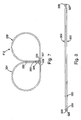
- a third alternative example 312 of the vehicle door beam is illustrated in Fig. 7 .
- the beam portion 312 includes a first lateral portion 322 and a second lateral portion 324.
- the two lateral portions 322 and 324 are not part of a single web, but rather are separate connected pieces.
- the first lateral portion 322 is a closed configuration wherein the lateral edge 327 engages and is welded to the lateral edge 326
- the second lateral portion 324 is a closed configuration in which the lateral edge 329 engages and is welded to the lateral edge 328.
- the two lateral portions are welded together along lines 332 and 333.
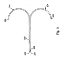
- Figs. 8 and 9 show two intermediate steps in fabricating the beam portion 312 illustrated in Fig. 7 .
- the two lateral portions 322 and 324 are pieces of flat stock laid against one another. The two pieces are welded or otherwise connected along lines 332 and 333.
- Fig. 9 illustrates a subsequent step in which the two lateral portions 322 and 324 are being formed into their closed configurations. Ultimately, the lateral edges 327 and 329 engage lateral edges 326 and 328 respectively and are welded thereto to complete the beam portion 312 illustrated in Fig. 7 .
- the profile of the beam portion is relatively small, and yet the beam meets or exceeds governmental regulations and vehicle manufacturer requirements.
- door beams constructed in accordance with the present invention can be longer than those of the prior art When roll formed, the door beams can be given a "sweep" or curve. Further when roll formed, the mounting brackets are relatively wide, providing increased surface attachment area. All of these advantages enable the present door beam to be used in a variety of applications in which prior art beams cannot be used. Therefore, the present invention enables a wider variety of vehicle door designs.
Landscapes
- Engineering & Computer Science (AREA)
- Mechanical Engineering (AREA)
- Body Structure For Vehicles (AREA)
- Laser Beam Processing (AREA)
- Bending Of Plates, Rods, And Pipes (AREA)
- Automobile Manufacture Line, Endless Track Vehicle, Trailer (AREA)
- Window Of Vehicle (AREA)
Claims (8)
- Renfort de portière pour véhicule, comprenant:une partie de renfort allongée (112) comprenant des extrémités opposées, ladite partie de renfort (112) comprenant des première et deuxième parties latérales (122 et 124) qui se terminent dans des premier et deuxième bords latéraux (126 et 128), respectivement, ledit premier bord latéral (126) s'appuyant sur une partie centrale de la partie de renfort (112), ledit premier bord latéral (126) étant soudé à ladite partie centrale le long d'une première ligne (130) pour former une première configuration fermée, ledit deuxième bord latéral (128) s'appuyant sur ladite première partie latérale (122), ledit bord latéral (128) étant soudé à ladite première partie latérale (122) le long d'une deuxième ligne (140) séparée de ladite première ligne (130) pour former une deuxième configuration fermée; etune paire de parties de console (14a et 14b) qui s'étendent à partir des extrémités opposées de ladite partie de renfort allongée (112) et qui sont adaptées pour être fixées à une portière de véhicule.
- Renfort de portière pour véhicule selon la revendication 1, dans lequel ladite partie de renfort (112) et lesdites parties de console (14a et 14b) sont des parties d'une seule pièce unitaire.
- Renfort de portière pour véhicule selon la revendication 1 ou 2, dans lequel les première et deuxième parties latérales (122 et 124) ont approximativement la même taille.
- Renfort de portière pour véhicule selon l'une quelconque des revendications 1 à 3, dans lequel lesdites configurations fermées sont formées au rouleau.
- Procédé de fabrication d'un renfort de portière pour véhicule à partir d'une pièce comprenant des première et deuxième parties latérales (122 et 124) qui se terminent dans des premier et deuxième bords latéraux (126 et 128), le procédé comprenant les étapes suivantes:former une première configuration fermée dans la première partie latérale de la pièce avec le premier bord latéral (126) qui s'appuie sur une partie centrale de la pièce;souder ledit premier bord latéral (126) à ladite pièce le long d'une première ligne (130);former une deuxième configuration fermée dans la deuxième partie latérale de la pièce avec le deuxième bord latéral (128) qui s'appuie sur la première partie latérale (122); etsouder ledit deuxième bord latéral (128) à ladite première partie latérale (122) le long d'une deuxième ligne (140) séparée de ladite première ligne (130).
- Procédé selon la revendication 5, dans lequel lesdites étapes de formage comprennent le formage des première et deuxième configurations fermées à partir de la même pièce intégrale.
- Procédé selon la revendication 5 ou 6, dans lequel les première et deuxième parties latérales (122 et 124) ont approximativement la même taille.
- Procédé selon l'une quelconque des revendications 5 à 7, dans lequel le formage desdites configurations fermées comprend un formage au rouleau.
Priority Applications (1)
| Application Number | Priority Date | Filing Date | Title |
|---|---|---|---|
| EP07021008A EP1880779A1 (fr) | 2003-03-28 | 2004-03-26 | Poutre de porte de véhicule hautement résistante à profil bas |
Applications Claiming Priority (2)
| Application Number | Priority Date | Filing Date | Title |
|---|---|---|---|
| US40246203A | 2003-03-28 | 2003-03-28 | |
| PCT/IB2004/050349 WO2004085091A1 (fr) | 2003-03-28 | 2004-03-26 | Renfort de portiere a resistance elevee et a profil bas pour vehicule |
Related Child Applications (1)
| Application Number | Title | Priority Date | Filing Date |
|---|---|---|---|
| EP07021008A Division EP1880779A1 (fr) | 2003-03-28 | 2004-03-26 | Poutre de porte de véhicule hautement résistante à profil bas |
Publications (2)
| Publication Number | Publication Date |
|---|---|
| EP1615736A1 EP1615736A1 (fr) | 2006-01-18 |
| EP1615736B1 true EP1615736B1 (fr) | 2008-12-24 |
Family
ID=32989703
Family Applications (2)
| Application Number | Title | Priority Date | Filing Date |
|---|---|---|---|
| EP04723681A Expired - Lifetime EP1615736B1 (fr) | 2003-03-28 | 2004-03-26 | Renfort de portiere a resistance elevee et a profil bas pour vehicule |
| EP07021008A Withdrawn EP1880779A1 (fr) | 2003-03-28 | 2004-03-26 | Poutre de porte de véhicule hautement résistante à profil bas |
Family Applications After (1)
| Application Number | Title | Priority Date | Filing Date |
|---|---|---|---|
| EP07021008A Withdrawn EP1880779A1 (fr) | 2003-03-28 | 2004-03-26 | Poutre de porte de véhicule hautement résistante à profil bas |
Country Status (9)
| Country | Link |
|---|---|
| US (3) | US7055886B2 (fr) |
| EP (2) | EP1615736B1 (fr) |
| JP (1) | JP2007535407A (fr) |
| CN (1) | CN1791482A (fr) |
| AT (1) | ATE418404T1 (fr) |
| CA (1) | CA2520296C (fr) |
| DE (1) | DE602004018628D1 (fr) |
| MX (1) | MXPA05010363A (fr) |
| WO (1) | WO2004085091A1 (fr) |
Families Citing this family (20)
| Publication number | Priority date | Publication date | Assignee | Title |
|---|---|---|---|---|
| DE102004049949C5 (de) * | 2004-10-13 | 2009-04-02 | Benteler Automobiltechnik Gmbh | Strukturbauteil für die Karosserie oder ein Fahrwerk eines Kraftfahrzeugs |
| US7093886B2 (en) * | 2004-12-17 | 2006-08-22 | Benteler Automotive Corporation | Vehicle door beam with reinforced tab and method for making the same |
| DE102005004779A1 (de) * | 2005-02-01 | 2006-08-10 | Wagon Automotive Gmbh | Aufprallträger für eine Kraftfahrzeugkarosserie |
| DE102005029738B4 (de) * | 2005-06-24 | 2018-10-04 | GM Global Technology Operations LLC (n. d. Ges. d. Staates Delaware) | Energieabsorberelement und dieses verwendende Kraftfahrzeugkarosserie |
| US20080093867A1 (en) * | 2006-10-24 | 2008-04-24 | Shape Corporation | B-shaped beam with integrally-formed rib in face |
| US7503601B2 (en) | 2007-05-31 | 2009-03-17 | Shape Corp. | B-shaped beam with radiused face but recessed center |
| USD608261S1 (en) * | 2008-09-12 | 2010-01-19 | Autech Japan, Inc | Side sill protector |
| US20100122981A1 (en) * | 2008-11-18 | 2010-05-20 | Evironmental Packaging Technologies Limited | Shipping container systems |
| DE102009011378B4 (de) * | 2009-03-05 | 2012-03-22 | Benteler Automobiltechnik Gmbh | Türaufprallträger |
| JP5424733B2 (ja) * | 2009-06-17 | 2014-02-26 | 小島プレス工業株式会社 | 補強ブレース |
| DE102009060319A1 (de) | 2009-12-23 | 2011-06-30 | DURA Automotive Body & Glass Systems GmbH, 58840 | Karosserieteil oder Strukturteil für ein Fahrzeug und ein Verfahren zu seiner Herstellung |
| DE102011052153A1 (de) * | 2011-07-26 | 2013-01-31 | Benteler Automobiltechnik Gmbh | Verfahren zur Herstellung eines Kraftfahrzeug-Biegeträgers und Kraftfahrzeug-Biegeträger |
| US9027309B2 (en) * | 2012-01-09 | 2015-05-12 | Consolidated Metal Products, Inc. | Welded hot-rolled high-strength steel structural members and methods |
| US9211858B2 (en) * | 2013-10-11 | 2015-12-15 | Shape Corp. | Beam with varied bending moment, apparatus, and method |
| DE102014115158B4 (de) * | 2014-10-17 | 2018-07-05 | Benteler Automobiltechnik Gmbh | Türaufprallträger aus Strangpressprofil und Verfahren zu dessen Herstellung |
| KR101896325B1 (ko) | 2016-11-15 | 2018-09-07 | 현대자동차 주식회사 | 차량용 cfrp 도어의 임팩트 빔 구조 |
| PL432278A1 (pl) * | 2019-12-18 | 2021-06-28 | Instytut Formy Spółka Z Ograniczoną Odpowiedzialnością | Wielokomorowy element konstrukcyjny oraz sposób wytwarzania wielokomorowego elementu konstrukcyjnego |
| MX2023012238A (es) * | 2021-05-26 | 2023-11-09 | Autotech Eng Sl | Viga de parachoques. |
| WO2025150431A1 (fr) * | 2024-01-10 | 2025-07-17 | 株式会社ジーテクト | Procédé de fabrication d'un composant de châssis moulé par moulage par profilage, et composant de châssis moulé par moulage par profilage |
| JP7614411B1 (ja) | 2024-01-10 | 2025-01-15 | 株式会社ジーテクト | ロールフォーム成形で成形されたフレーム部品の製造方法 |
Family Cites Families (55)
| Publication number | Priority date | Publication date | Assignee | Title |
|---|---|---|---|---|
| FR577235A (fr) * | 1923-03-24 | 1924-09-02 | Gardy Sa | Disposition d'isolation pour bornes électriques |
| JPS5639698Y2 (fr) * | 1975-10-01 | 1981-09-16 | ||
| US4307911A (en) * | 1980-02-04 | 1981-12-29 | The Budd Company | Reinforcement means for resisting side impacts against an automobile door |
| US4684166A (en) * | 1986-05-19 | 1987-08-04 | General Motors Corporation | Vehicle door impact beam and stabilizing assembly |
| US4796946A (en) * | 1987-09-04 | 1989-01-10 | Inland Steel Company | Automotive vehicle door and bar reinforcement |
| US5395036A (en) * | 1990-03-26 | 1995-03-07 | Shape Corporation | Method of roll-forming an end automotive bumper |
| US5409255A (en) * | 1990-08-10 | 1995-04-25 | Benteler Industries, Inc. | Twist beam axle |
| US5080427A (en) * | 1990-11-13 | 1992-01-14 | Shape Corporation | Impact beam |
| JP3052381B2 (ja) | 1991-01-14 | 2000-06-12 | トヨタ自動車株式会社 | 自動車ドア用インパクトビーム |
| DE9200388U1 (de) | 1991-08-02 | 1992-04-23 | Mussbach Metall Hackelsberger GmbH & Co, 6730 Neustadt | Rohrförmiges Profil für die Verstärkung von Kfz-Türen gegen Seitenaufprall |
| NO173537C (no) * | 1991-09-06 | 1993-12-29 | Norsk Hydro As | Forsterkningsbjelke og kjoeretoeydoer med bjelken |
| US5232261A (en) * | 1992-06-04 | 1993-08-03 | Nhk Spring Co., Ltd. | Door impact beam for an automobile |
| DE9208957U1 (de) * | 1992-06-30 | 1992-09-10 | Mannesmann AG, 4000 Düsseldorf | Hohlprofil für die Verstärkung einer Kraftfahrzeugtür |
| DE4224303A1 (de) * | 1992-07-23 | 1994-01-27 | Albert Griesemer | Verstärkungselement für Seitenwände von Automobilen sowie Verfahren zur Herstellung derartiger Verstärkungselemente |
| SE501812C2 (sv) * | 1992-09-25 | 1995-05-22 | Plannja Hardtech Ab | Skyddsbalk i fordon |
| US5277470A (en) * | 1992-10-21 | 1994-01-11 | The Budd Company | Tapered intrusion beam for reinforcing a vehicle door |
| DE4241196A1 (de) * | 1992-12-08 | 1994-06-09 | Benteler Werke Ag | Rohrförmiger Verstärkungsträger |
| US5404690A (en) * | 1993-03-26 | 1995-04-11 | Crescive Die & Tool, Inc. | Impact beam assembly method and apparatus |
| EP0685355A1 (fr) * | 1994-05-30 | 1995-12-06 | Schade Kg | Poutre de choc |
| ES2129788T3 (es) * | 1994-12-23 | 1999-06-16 | Alusuisse Lonza Services Ag | Parachoques para vehiculos. |
| JP3763858B2 (ja) * | 1995-02-14 | 2006-04-05 | ユニプレス株式会社 | 自動車用ドアのガードビーム |
| US5580120A (en) * | 1995-02-23 | 1996-12-03 | Mascotech Tubular Products, Inc. | Vehicle door intrusion beam |
| US5756167A (en) * | 1995-04-07 | 1998-05-26 | Hashimoto Forming Industry Co., Ltd. | Rigid elongated member for use in vehicles and producing method and apparatus therefor |
| US5785376A (en) * | 1995-06-21 | 1998-07-28 | Mascotech Tubular Products, Inc. | Vehicle door beam |
| JPH0986172A (ja) * | 1995-09-25 | 1997-03-31 | Yorozu:Kk | 自動車用ドアガードバー |
| JP3476292B2 (ja) | 1995-11-14 | 2003-12-10 | 享栄エンジニアリング株式会社 | 保護バー及びその製造法 |
| SE9601246L (sv) * | 1996-04-01 | 1997-10-02 | Plannja Hardtech Ab | Skyddsbalk |
| US6003912A (en) * | 1996-04-09 | 1999-12-21 | Chrysler Corporation | Bi-metal vehicle bumper structure |
| JP3723289B2 (ja) * | 1996-08-16 | 2005-12-07 | ユニプレス株式会社 | 自動車用ドアのガードビーム |
| DE19639280B4 (de) * | 1996-09-25 | 2005-01-13 | Wagon Automotive Gmbh | Kraftfahrzeugtür |
| US5755484A (en) * | 1996-10-28 | 1998-05-26 | Ford Global Technologies, Inc. | Vehicle door intrusion beam |
| DE19647334B4 (de) * | 1996-11-15 | 2004-07-15 | Benteler Ag | Seitenaufprallträger für einen Personenkraftwagen |
| DE19653959C1 (de) * | 1996-12-21 | 1998-02-05 | Benteler Werke Ag | Querträger und Verfahren zum Herstellen eines Querträgers |
| DE19654376B4 (de) * | 1996-12-24 | 2005-08-04 | Thyssen Krupp Automotive Gmbh | Seitenaufprallträger für Kfz-Türen |
| KR100206023B1 (en) * | 1997-04-10 | 1999-07-01 | Hyundai Motor Co Ltd | Method of roll-forming an automotive bumper |
| DE19726720C1 (de) * | 1997-06-24 | 1998-10-08 | Daimler Benz Ag | Strukturbauteil |
| US6096403A (en) * | 1997-07-21 | 2000-08-01 | Henkel Corporation | Reinforced structural members |
| JPH1159181A (ja) | 1997-08-11 | 1999-03-02 | Futaba Ind Co Ltd | インパクトビーム |
| JP3947278B2 (ja) * | 1997-09-10 | 2007-07-18 | 富士重工業株式会社 | 車両のドアロック解除機構 |
| JPH1191352A (ja) * | 1997-09-24 | 1999-04-06 | Sanyo Mach Works Ltd | インパクトバーおよびその製造方法 |
| JPH11227459A (ja) | 1998-02-12 | 1999-08-24 | Daihatsu Motor Co Ltd | 自動車用ドアのインパクトビーム |
| US6240820B1 (en) * | 1998-05-19 | 2001-06-05 | Shape Corporation | Die apparatus for cutting end of bumper bar |
| US6428080B1 (en) * | 1998-07-16 | 2002-08-06 | Carlos M. Ochoa | Stiffeners for automotive vehicle closures |
| US6357816B1 (en) * | 1998-07-29 | 2002-03-19 | Conix Corporation | Bumper beam extensions |
| BR9913772A (pt) * | 1998-09-16 | 2001-06-05 | Cosma Int Inc | Viga de reforço de porta de veìculo e processo para fabricar a mesma |
| JP3613702B2 (ja) * | 1999-09-21 | 2005-01-26 | トヨタ自動車株式会社 | 閉断面を有する構造部材、その製造装置およびその製造方法 |
| DE19954647C2 (de) * | 1999-11-13 | 2003-12-11 | Benteler Werke Ag | Seitenaufprallträger |
| US6217089B1 (en) * | 1999-12-01 | 2001-04-17 | Om Corporation | Bumper reinforcing member |
| US6485072B1 (en) * | 1999-12-15 | 2002-11-26 | Ford Global Technologies, Inc. | Bumper system for motor vehicles |
| DE10013527A1 (de) * | 2000-03-20 | 2001-10-11 | Benteler Werke Ag | Verfahren zur Herstellung eines Bestandteil eines Stoßfängers bildenden stählernen Querträgers für Kraftfahrzeuge und Querträger |
| US6454884B1 (en) * | 2000-06-12 | 2002-09-24 | Pullman Industries, Inc. | Method of manufacturing a vehicle structural beam |
| JP2002012032A (ja) * | 2000-07-03 | 2002-01-15 | Om Kogyo Kk | 自動車ドア補強材 |
| US6508035B1 (en) * | 2000-07-25 | 2003-01-21 | Alcoa Inc. | Ultra-lightweight thin sliding door for a vehicle |
| JP2003237507A (ja) * | 2002-02-19 | 2003-08-27 | Om Kogyo Kk | バンパ補強材 |
| US6948749B2 (en) * | 2004-01-26 | 2005-09-27 | Trim Trends Co., Llc | Cross member for vehicle bumper bar and method for making same |
-
2004
- 2004-02-05 US US10/772,607 patent/US7055886B2/en not_active Expired - Fee Related
- 2004-03-26 EP EP04723681A patent/EP1615736B1/fr not_active Expired - Lifetime
- 2004-03-26 MX MXPA05010363A patent/MXPA05010363A/es not_active Application Discontinuation
- 2004-03-26 JP JP2006506782A patent/JP2007535407A/ja not_active Withdrawn
- 2004-03-26 CA CA002520296A patent/CA2520296C/fr not_active Expired - Fee Related
- 2004-03-26 AT AT04723681T patent/ATE418404T1/de not_active IP Right Cessation
- 2004-03-26 EP EP07021008A patent/EP1880779A1/fr not_active Withdrawn
- 2004-03-26 CN CNA2004800083066A patent/CN1791482A/zh active Pending
- 2004-03-26 WO PCT/IB2004/050349 patent/WO2004085091A1/fr not_active Ceased
- 2004-03-26 DE DE602004018628T patent/DE602004018628D1/de not_active Expired - Fee Related
- 2004-09-21 US US10/945,592 patent/US6896314B2/en not_active Expired - Fee Related
-
2005
- 2005-09-22 US US11/233,284 patent/US7182393B2/en not_active Expired - Fee Related
Also Published As
| Publication number | Publication date |
|---|---|
| US20060017305A1 (en) | 2006-01-26 |
| US20040189043A1 (en) | 2004-09-30 |
| WO2004085091A1 (fr) | 2004-10-07 |
| CN1791482A (zh) | 2006-06-21 |
| EP1615736A1 (fr) | 2006-01-18 |
| US20050035625A1 (en) | 2005-02-17 |
| US6896314B2 (en) | 2005-05-24 |
| JP2007535407A (ja) | 2007-12-06 |
| ATE418404T1 (de) | 2009-01-15 |
| DE602004018628D1 (de) | 2009-02-05 |
| EP1880779A1 (fr) | 2008-01-23 |
| CA2520296A1 (fr) | 2004-10-07 |
| US7182393B2 (en) | 2007-02-27 |
| MXPA05010363A (es) | 2005-11-17 |
| US7055886B2 (en) | 2006-06-06 |
| CA2520296C (fr) | 2008-12-23 |
Similar Documents
| Publication | Publication Date | Title |
|---|---|---|
| US6896314B2 (en) | Low-profile high-strength vehicle door beam | |
| EP1461220B1 (fr) | Renfort de porte tubulaire presentant une epaisseur variable | |
| EP1299257B1 (fr) | Renfort lateral de porte forme par laminage et emboutissage | |
| US8651562B2 (en) | B-pillar reinforcement of a motor vehicle | |
| US20040130166A1 (en) | Profile for an automobile structural element and corresponding chassis | |
| JPH11129045A (ja) | 構造部材 | |
| JP2010012891A (ja) | 車両用ドアサッシュ | |
| US20070163121A1 (en) | Metal frame and method for manufacturing the same | |
| US7448670B2 (en) | Vehicle door reinforcement | |
| JP4450747B2 (ja) | 自動車のクロスメンバー、自動車のフレーム構造及びルーフ構造 | |
| US20080035628A1 (en) | Production of Ihpf Components Having a Flange | |
| EP1420996B1 (fr) | Chassis pour vehicule lourd | |
| JP2006341687A (ja) | 車体骨格部材の衝突エネルギー吸収構造および衝突エネルギー吸収方法 | |
| US20030204945A1 (en) | Body side panel for a motor vehicle | |
| EP2774808B1 (fr) | Structure d'attachement d'élément de saisie d'assistance | |
| EP1762438A1 (fr) | Dispositif d'absorption de chocs pour un véhicule à moteur | |
| EP1296781B1 (fr) | Procede pour fabriquer un element de structure avec un coude renforce et un element de structure | |
| US7703207B2 (en) | Blank, chassis component and method for production of said chassis component | |
| WO2007089057A1 (fr) | Poutre d'impact de véhicule automobile à supports intégrés et son procédé de fabrication | |
| US7975383B2 (en) | Double hydroformed tube with integral reinforcement | |
| JP3593191B2 (ja) | シートベルトアンカの取付方法 |
Legal Events
| Date | Code | Title | Description |
|---|---|---|---|
| PUAI | Public reference made under article 153(3) epc to a published international application that has entered the european phase |
Free format text: ORIGINAL CODE: 0009012 |
|
| 17P | Request for examination filed |
Effective date: 20051025 |
|
| AK | Designated contracting states |
Kind code of ref document: A1 Designated state(s): AT BE BG CH CY CZ DE DK EE ES FI FR GB GR HU IE IT LI LU MC NL PL PT RO SE SI SK TR |
|
| AX | Request for extension of the european patent |
Extension state: AL LT LV MK |
|
| DAX | Request for extension of the european patent (deleted) | ||
| 17Q | First examination report despatched |
Effective date: 20070118 |
|
| GRAP | Despatch of communication of intention to grant a patent |
Free format text: ORIGINAL CODE: EPIDOSNIGR1 |
|
| RAP1 | Party data changed (applicant data changed or rights of an application transferred) |
Owner name: SHAPE CORPORATION |
|
| GRAS | Grant fee paid |
Free format text: ORIGINAL CODE: EPIDOSNIGR3 |
|
| GRAA | (expected) grant |
Free format text: ORIGINAL CODE: 0009210 |
|
| AK | Designated contracting states |
Kind code of ref document: B1 Designated state(s): AT BE BG CH CY CZ DE DK EE ES FI FR GB GR HU IE IT LI LU MC NL PL PT RO SE SI SK TR |
|
| REG | Reference to a national code |
Ref country code: GB Ref legal event code: FG4D |
|
| REG | Reference to a national code |
Ref country code: CH Ref legal event code: EP |
|
| REG | Reference to a national code |
Ref country code: IE Ref legal event code: FG4D |
|
| REF | Corresponds to: |
Ref document number: 602004018628 Country of ref document: DE Date of ref document: 20090205 Kind code of ref document: P |
|
| PG25 | Lapsed in a contracting state [announced via postgrant information from national office to epo] |
Ref country code: NL Free format text: LAPSE BECAUSE OF FAILURE TO SUBMIT A TRANSLATION OF THE DESCRIPTION OR TO PAY THE FEE WITHIN THE PRESCRIBED TIME-LIMIT Effective date: 20081224 Ref country code: FI Free format text: LAPSE BECAUSE OF FAILURE TO SUBMIT A TRANSLATION OF THE DESCRIPTION OR TO PAY THE FEE WITHIN THE PRESCRIBED TIME-LIMIT Effective date: 20081224 Ref country code: SI Free format text: LAPSE BECAUSE OF FAILURE TO SUBMIT A TRANSLATION OF THE DESCRIPTION OR TO PAY THE FEE WITHIN THE PRESCRIBED TIME-LIMIT Effective date: 20081224 Ref country code: PL Free format text: LAPSE BECAUSE OF FAILURE TO SUBMIT A TRANSLATION OF THE DESCRIPTION OR TO PAY THE FEE WITHIN THE PRESCRIBED TIME-LIMIT Effective date: 20081224 |
|
| NLV1 | Nl: lapsed or annulled due to failure to fulfill the requirements of art. 29p and 29m of the patents act | ||
| PGFP | Annual fee paid to national office [announced via postgrant information from national office to epo] |
Ref country code: GB Payment date: 20090122 Year of fee payment: 6 |
|
| PG25 | Lapsed in a contracting state [announced via postgrant information from national office to epo] |
Ref country code: ES Free format text: LAPSE BECAUSE OF FAILURE TO SUBMIT A TRANSLATION OF THE DESCRIPTION OR TO PAY THE FEE WITHIN THE PRESCRIBED TIME-LIMIT Effective date: 20090404 Ref country code: RO Free format text: LAPSE BECAUSE OF FAILURE TO SUBMIT A TRANSLATION OF THE DESCRIPTION OR TO PAY THE FEE WITHIN THE PRESCRIBED TIME-LIMIT Effective date: 20081224 Ref country code: EE Free format text: LAPSE BECAUSE OF FAILURE TO SUBMIT A TRANSLATION OF THE DESCRIPTION OR TO PAY THE FEE WITHIN THE PRESCRIBED TIME-LIMIT Effective date: 20081224 Ref country code: BE Free format text: LAPSE BECAUSE OF FAILURE TO SUBMIT A TRANSLATION OF THE DESCRIPTION OR TO PAY THE FEE WITHIN THE PRESCRIBED TIME-LIMIT Effective date: 20081224 Ref country code: BG Free format text: LAPSE BECAUSE OF FAILURE TO SUBMIT A TRANSLATION OF THE DESCRIPTION OR TO PAY THE FEE WITHIN THE PRESCRIBED TIME-LIMIT Effective date: 20090324 |
|
| PG25 | Lapsed in a contracting state [announced via postgrant information from national office to epo] |
Ref country code: CZ Free format text: LAPSE BECAUSE OF FAILURE TO SUBMIT A TRANSLATION OF THE DESCRIPTION OR TO PAY THE FEE WITHIN THE PRESCRIBED TIME-LIMIT Effective date: 20081224 Ref country code: SE Free format text: LAPSE BECAUSE OF FAILURE TO SUBMIT A TRANSLATION OF THE DESCRIPTION OR TO PAY THE FEE WITHIN THE PRESCRIBED TIME-LIMIT Effective date: 20090324 Ref country code: PT Free format text: LAPSE BECAUSE OF FAILURE TO SUBMIT A TRANSLATION OF THE DESCRIPTION OR TO PAY THE FEE WITHIN THE PRESCRIBED TIME-LIMIT Effective date: 20090525 Ref country code: AT Free format text: LAPSE BECAUSE OF FAILURE TO SUBMIT A TRANSLATION OF THE DESCRIPTION OR TO PAY THE FEE WITHIN THE PRESCRIBED TIME-LIMIT Effective date: 20081224 |
|
| PGFP | Annual fee paid to national office [announced via postgrant information from national office to epo] |
Ref country code: DE Payment date: 20090227 Year of fee payment: 6 |
|
| PG25 | Lapsed in a contracting state [announced via postgrant information from national office to epo] |
Ref country code: SK Free format text: LAPSE BECAUSE OF FAILURE TO SUBMIT A TRANSLATION OF THE DESCRIPTION OR TO PAY THE FEE WITHIN THE PRESCRIBED TIME-LIMIT Effective date: 20081224 |
|
| PG25 | Lapsed in a contracting state [announced via postgrant information from national office to epo] |
Ref country code: DK Free format text: LAPSE BECAUSE OF FAILURE TO SUBMIT A TRANSLATION OF THE DESCRIPTION OR TO PAY THE FEE WITHIN THE PRESCRIBED TIME-LIMIT Effective date: 20081224 Ref country code: MC Free format text: LAPSE BECAUSE OF NON-PAYMENT OF DUE FEES Effective date: 20090331 |
|
| PGFP | Annual fee paid to national office [announced via postgrant information from national office to epo] |
Ref country code: FR Payment date: 20090122 Year of fee payment: 6 |
|
| PLBE | No opposition filed within time limit |
Free format text: ORIGINAL CODE: 0009261 |
|
| REG | Reference to a national code |
Ref country code: CH Ref legal event code: PL |
|
| STAA | Information on the status of an ep patent application or granted ep patent |
Free format text: STATUS: NO OPPOSITION FILED WITHIN TIME LIMIT |
|
| 26N | No opposition filed |
Effective date: 20090925 |
|
| REG | Reference to a national code |
Ref country code: IE Ref legal event code: MM4A |
|
| PG25 | Lapsed in a contracting state [announced via postgrant information from national office to epo] |
Ref country code: CH Free format text: LAPSE BECAUSE OF NON-PAYMENT OF DUE FEES Effective date: 20090331 Ref country code: LI Free format text: LAPSE BECAUSE OF NON-PAYMENT OF DUE FEES Effective date: 20090331 Ref country code: IE Free format text: LAPSE BECAUSE OF NON-PAYMENT OF DUE FEES Effective date: 20090326 |
|
| PG25 | Lapsed in a contracting state [announced via postgrant information from national office to epo] |
Ref country code: GR Free format text: LAPSE BECAUSE OF FAILURE TO SUBMIT A TRANSLATION OF THE DESCRIPTION OR TO PAY THE FEE WITHIN THE PRESCRIBED TIME-LIMIT Effective date: 20090325 |
|
| GBPC | Gb: european patent ceased through non-payment of renewal fee |
Effective date: 20100326 |
|
| REG | Reference to a national code |
Ref country code: FR Ref legal event code: ST Effective date: 20101130 |
|
| PG25 | Lapsed in a contracting state [announced via postgrant information from national office to epo] |
Ref country code: FR Free format text: LAPSE BECAUSE OF NON-PAYMENT OF DUE FEES Effective date: 20100331 |
|
| PG25 | Lapsed in a contracting state [announced via postgrant information from national office to epo] |
Ref country code: DE Free format text: LAPSE BECAUSE OF NON-PAYMENT OF DUE FEES Effective date: 20101001 |
|
| PG25 | Lapsed in a contracting state [announced via postgrant information from national office to epo] |
Ref country code: GB Free format text: LAPSE BECAUSE OF NON-PAYMENT OF DUE FEES Effective date: 20100326 Ref country code: IT Free format text: LAPSE BECAUSE OF FAILURE TO SUBMIT A TRANSLATION OF THE DESCRIPTION OR TO PAY THE FEE WITHIN THE PRESCRIBED TIME-LIMIT Effective date: 20081224 |
|
| PG25 | Lapsed in a contracting state [announced via postgrant information from national office to epo] |
Ref country code: LU Free format text: LAPSE BECAUSE OF NON-PAYMENT OF DUE FEES Effective date: 20090326 |
|
| PG25 | Lapsed in a contracting state [announced via postgrant information from national office to epo] |
Ref country code: HU Free format text: LAPSE BECAUSE OF FAILURE TO SUBMIT A TRANSLATION OF THE DESCRIPTION OR TO PAY THE FEE WITHIN THE PRESCRIBED TIME-LIMIT Effective date: 20090625 |
|
| PG25 | Lapsed in a contracting state [announced via postgrant information from national office to epo] |
Ref country code: TR Free format text: LAPSE BECAUSE OF FAILURE TO SUBMIT A TRANSLATION OF THE DESCRIPTION OR TO PAY THE FEE WITHIN THE PRESCRIBED TIME-LIMIT Effective date: 20081224 |
|
| PG25 | Lapsed in a contracting state [announced via postgrant information from national office to epo] |
Ref country code: CY Free format text: LAPSE BECAUSE OF FAILURE TO SUBMIT A TRANSLATION OF THE DESCRIPTION OR TO PAY THE FEE WITHIN THE PRESCRIBED TIME-LIMIT Effective date: 20081224 |