EP1617143A2 - Barreau de grille, grille et incinerateur équipés dudit barreau - Google Patents
Barreau de grille, grille et incinerateur équipés dudit barreau Download PDFInfo
- Publication number
- EP1617143A2 EP1617143A2 EP05014330A EP05014330A EP1617143A2 EP 1617143 A2 EP1617143 A2 EP 1617143A2 EP 05014330 A EP05014330 A EP 05014330A EP 05014330 A EP05014330 A EP 05014330A EP 1617143 A2 EP1617143 A2 EP 1617143A2
- Authority
- EP
- European Patent Office
- Prior art keywords
- grate
- grate plate
- adjacent
- channel
- plate according
- Prior art date
- Legal status (The legal status is an assumption and is not a legal conclusion. Google has not performed a legal analysis and makes no representation as to the accuracy of the status listed.)
- Granted
Links
- 238000002485 combustion reaction Methods 0.000 claims abstract description 37
- IHQKEDIOMGYHEB-UHFFFAOYSA-M sodium dimethylarsinate Chemical class [Na+].C[As](C)([O-])=O IHQKEDIOMGYHEB-UHFFFAOYSA-M 0.000 claims description 8
- 239000002826 coolant Substances 0.000 claims description 7
- 239000012809 cooling fluid Substances 0.000 abstract 1
- 238000001816 cooling Methods 0.000 description 34
- XLYOFNOQVPJJNP-UHFFFAOYSA-N water Substances O XLYOFNOQVPJJNP-UHFFFAOYSA-N 0.000 description 10
- 239000000463 material Substances 0.000 description 5
- 238000010304 firing Methods 0.000 description 4
- 239000012530 fluid Substances 0.000 description 4
- 238000004056 waste incineration Methods 0.000 description 4
- 230000000694 effects Effects 0.000 description 3
- 239000000446 fuel Substances 0.000 description 3
- JEIPFZHSYJVQDO-UHFFFAOYSA-N iron(III) oxide Inorganic materials O=[Fe]O[Fe]=O JEIPFZHSYJVQDO-UHFFFAOYSA-N 0.000 description 3
- 238000000034 method Methods 0.000 description 3
- 239000002699 waste material Substances 0.000 description 3
- 239000002023 wood Substances 0.000 description 3
- 239000010791 domestic waste Substances 0.000 description 2
- 238000005516 engineering process Methods 0.000 description 2
- 239000007788 liquid Substances 0.000 description 2
- 238000001556 precipitation Methods 0.000 description 2
- 230000000284 resting effect Effects 0.000 description 2
- 239000002028 Biomass Substances 0.000 description 1
- 229910001018 Cast iron Inorganic materials 0.000 description 1
- 230000015572 biosynthetic process Effects 0.000 description 1
- 238000005266 casting Methods 0.000 description 1
- 238000010276 construction Methods 0.000 description 1
- 238000005260 corrosion Methods 0.000 description 1
- 230000007797 corrosion Effects 0.000 description 1
- 238000007599 discharging Methods 0.000 description 1
- 230000003628 erosive effect Effects 0.000 description 1
- 230000002349 favourable effect Effects 0.000 description 1
- 238000011065 in-situ storage Methods 0.000 description 1
- 239000002440 industrial waste Substances 0.000 description 1
- 229910052751 metal Inorganic materials 0.000 description 1
- 239000002184 metal Substances 0.000 description 1
- 150000002739 metals Chemical class 0.000 description 1
- 239000002244 precipitate Substances 0.000 description 1
- 239000003473 refuse derived fuel Substances 0.000 description 1
- 230000000630 rising effect Effects 0.000 description 1
- 238000005201 scrubbing Methods 0.000 description 1
- 239000010801 sewage sludge Substances 0.000 description 1
- 239000002893 slag Substances 0.000 description 1
Images

Classifications
-
- F—MECHANICAL ENGINEERING; LIGHTING; HEATING; WEAPONS; BLASTING
- F23—COMBUSTION APPARATUS; COMBUSTION PROCESSES
- F23H—GRATES; CLEANING OR RAKING GRATES
- F23H3/00—Grates with hollow bars
- F23H3/02—Grates with hollow bars internally cooled
-
- F—MECHANICAL ENGINEERING; LIGHTING; HEATING; WEAPONS; BLASTING
- F23—COMBUSTION APPARATUS; COMBUSTION PROCESSES
- F23H—GRATES; CLEANING OR RAKING GRATES
- F23H17/00—Details of grates
- F23H17/12—Fire-bars
-
- F—MECHANICAL ENGINEERING; LIGHTING; HEATING; WEAPONS; BLASTING
- F23—COMBUSTION APPARATUS; COMBUSTION PROCESSES
- F23H—GRATES; CLEANING OR RAKING GRATES
- F23H3/00—Grates with hollow bars
- F23H3/04—Grates with hollow bars externally cooled, e.g. with water, steam or air
-
- F—MECHANICAL ENGINEERING; LIGHTING; HEATING; WEAPONS; BLASTING
- F23—COMBUSTION APPARATUS; COMBUSTION PROCESSES
- F23H—GRATES; CLEANING OR RAKING GRATES
- F23H2900/00—Special features of combustion grates
- F23H2900/03021—Liquid cooled grates
Definitions
- the invention relates to a grate plate for a combustion grate, a grate formed from grate plates and a waste incineration plant with such a combustion grate.
- the most important component of a waste incineration plant is the combustion grate, which is arranged horizontally or inclined and on which the firing material, for example refuse, is conveyed from a first end to a second end, usually Ausbrandrost.
- the required combustion air is forced through the combustion grate.
- corresponding openings are provided in the grate.
- combustion grates there are several types of combustion grates, including but not limited to the so-called booster combustion grate.
- a grate has moving parts (grate plates) which are suitable for carrying out scrubbing, whereby the kiln (the residue) is conveyed on the combustion grate.
- the individual grate plates staggered in relation to each other in the region of their side facing the combustion chamber, lie on top of one another. If, for example, every second grate plate is movably arranged, it is achieved by the movement of this grate plate that the residue, which rests on the grate plate following in the transport direction, is transported on to the next grate plate.
- RDF refuse derived fuel
- the individual types of residue differ with regard to their calorific value. However, this also applies within the individual types of residues.
- household waste may have a calorific value between 5 and 20 MJ / kg. Depending on this calorific value, the thermal and mechanical stress of the combustion grate or its grate plates changes.
- An air-cooled combustion grate describes the EP 0 391 146 A1. At an assumed temperature in the combustion chamber of 900 ° - 1,250 ° C and a temperature in the resting on the combustion grate furnace layer of> 800 ° C, the temperature of these air-cooled grate plates on their surface, for example 400 ° - 600 ° C,
- the grate plates with a liquid, especially water are cooled (EP 954 722 B1).
- the procedural outlay for water cooling is significantly higher than for air cooling.
- the more intensive water cooling leads to undesirably intensive cooling of the grate plates, in which the temperature at the surface of the grate plates can be 90 ° -110 ° C., at a temperature in the firing layer (on the combustion grate) of, for example, 700 ° -800 ° ° C.
- the object of the invention is to provide a way to make the known systems variable in terms of their application.
- each grate plate is above all to the firebox, so in particular exposed at its top and front end, a particularly intense heat load.
- Primary air is directed against the underside of the grate plates, so it cools from below, and is forced through openings in the grate plates or between the grate plates in the lying on the grate plates Brenngut Anlagen.
- the heat-loaded part of each grate plate is on the underside of a certain cooling volume to dissipate the heat generated. However, especially in the edge region, the cooling is insufficient.
- Such areas for example, the combustion chamber facing end side (longitudinal side) of a grate plate, are therefore particularly susceptible to corrosion and erosion.
- a first approach provides in this context, the area below the top and next to the front side longitudinal side of the grate plate with at least one flow channel, along the air from below targeted against the top or the adjacent front longitudinal side is performed.
- this at least one flow channel is designed such that it has an air outlet opening on the portion of the corresponding end face (end face) adjacent to the underside, so that the air flow is then deliberately guided onto the surface of the grate plate following in the direction of transport of the firing material and this surface likewise cools.
- a channel which is traversed by a cooling medium such as a fluid and / or a gas.
- the "back" part of the grate plate is intensively cooled with a liquid, while the same plate (rust stage) is cooled in the front part (the firing and combustion chamber adjacent) with air, with increased cooling effect over a known air cooling.
- the "front" grate plate part can also be cooled conventionally with air, for example, instead of the air cooling along the flow channel air is simply guided from below against the grate plate in this section.
- the grate plate is formed below the top with a plurality of recesses extending from an area adjacent to the first longitudinal side to an area adjacent to the second longitudinal side and open to the bottom.
- the flow channel or the flow channels extend according to an embodiment perpendicular to the longitudinal side of the grate plate.
- the air flow along the flow channels extends in the direction of the front end surface of the grate plate.
- the length of the flow channel can normally be limited to a length corresponding to 10-50% of the width of the grate plate, with a length between 10 and 30% or 10 and 20% usually sufficient. This is especially the section that is not swept over by a booster combustion grate. Accordingly, about 10 to 80% of the width of the grate plate is available for the formation of the channel, with 40 to 70% frequently being favorable. Basically, the areas in which the channel or the flow channel runs, could also overlap.
- the channel can extend substantially over the entire length of the grate plate and extend between the broad sides helical or meander-shaped to increase the length of the cooling channel.
- the supply and removal of the cooling medium takes place, for example, as described in EP 954 722 B1, reference is made to the.
- a grate plate on the circumference no exact cuboid shape.
- the front end face (second longitudinal side) therefore does not run perpendicular to the top of the grate plate. Rather, the second longitudinal side can extend at an angle ⁇ ⁇ 90 ° to the upper side and optionally additionally have at least one further bend.
- the flow channel is not rectilinear, but follows the shape of the grate plate in this area, that is, for example - describes - on average - a semicircle or has several bends. In this way, at the same time results in an extension of the flow channel.
- An intensification of the cooling is achieved when the flow channel is relatively close to the respective surface areas of the grate plate.
- an upper (outer) boundary wall of the flow channel is formed by an (inner) surface of the upper side and an (inner) surface of the second longitudinal side.
- a lower (inner) boundary wall for the flow channel can be formed by a rib which extends between walls or webs which form, for example, lateral boundaries of said recesses.
- Is the underside of the grate plate also called rust level
- rust level designed so that the top of the grate plate when resting the grate plate on a horizontal surface from the first longitudinal side to the second longitudinal side (ie from back to front) rising (slope, for example: 3-10 ° )
- slope for example: 3-10 °
- the corresponding grate plate with this paragraph is on the following in the direction of transport of the fuel grate plate (rust level).
- its front longitudinal side terminates preferably at a distance from the upper side of the following grate plate, and correspondingly, the outlet opening of the flow channel is also above the contact surface of the following grate plate. In this way, the targeted flow of the surface of the adjacent grate plate is additionally favored. This too is illustrated and explained in the following description of the figures.
- the additional cooling creates the possibility of making the sections of the grate plate which are adjacent to the flow channel thinner than the remaining sections of the grate plate. This not only saves material, but also increases the cooling effect.
- This "thinner” section can refer not only to the front longitudinal side of the grate plate, but also to the adjacent portion of the top of the grate plate.
- the other (first) part of the top of the grate plate, however, is “thicker", because in this section runs the channel.
- Grate plates of the type mentioned have a width of 40-60 cm and a length of several meters.
- grate bars may be castings, wherein the flow channel and the channel can be formed in-situ. Each section is thus one piece.
- the sections (grate bars) can also be composed of sub-sections, especially if they are made of sheets be welded.
- a grate bar for example, a width (in the longitudinal direction of the entire grate plate) of 30-100 cm, but also beyond.
- connection of adjacent grate bars by means of known connection technology, for example by screwing or in that a plurality of grate bars are connected to each other via connecting rods. Groups of grate bars formed in this way can in turn be connected to each other analogously.
- connection technology for example by screwing or in that a plurality of grate bars are connected to each other via connecting rods. Groups of grate bars formed in this way can in turn be connected to each other analogously.
- constructive solutions are shown, which can also be seen how connections of channel sections of the grate bars flow-related.
- the grate plates in such a way that at least one recess of two adjoining grate bars (sections) is formed, so a grate bar forms a part, for example, one half of the corresponding recess.
- a flow channel can also be formed by two grate bars.
- the invention further relates to a combustion grate, in particular a Schubverbrennungsrost, with a plurality of grate plates of the aforementioned type.
- shear combustion grate includes all types of shear combustion grates, regardless of whether they are horizontal or inclined or the kiln is conveyed in one direction or the other.
- shear combustion grate is also not limiting insofar as she decorations are detected in which, for example, every other grate plate is movably arranged, but also such grates in which more than a stationary grate plate are placed between grate plates that perform Schürhübe.
- the invention comprises a waste incineration plant, for example a waste incineration plant, with a combustion grate of the aforementioned type.
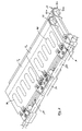
- the grate plate has an upper side 10, a lower side 12, a rear longitudinal side 14, a front longitudinal side 16 and correspondingly two broad sides, which can not be seen due to the sectional view.
- the upper end face 10o of the upper side 10 is flat.
- the front, second longitudinal side 16 is angled at an angle ⁇ (approximately 45 °) with respect to the surface 10o and then has an angling 16w.
- the grate plate Adjacent to the first (rear) longitudinal side 14, the grate plate on the underside a longitudinally extending (in the plane) recess 18, in which a connector 19 is placed, which has a further recess 19o, in which a round rod 20 is located, on which the grate plate (indirectly) is supported.
- a connector 19 Adjacent to the first (rear) longitudinal side 14, the grate plate on the underside a longitudinally extending (in the plane) recess 18, in which a connector 19 is placed, which has a further recess 19o, in which a round rod 20 is located, on which the grate plate (indirectly) is supported.
- this round rod 20 With the help of this round rod 20, the grate plate shown in Figure 1 in the direction of arrow P is movable.
- the connector 19 will be described later in detail.
- each grate plate is formed with a plurality of juxtaposed recesses 22.
- Each recess 22 is bounded laterally (parallel to the broad sides) of walls, in which case only one wall 24 can be seen.
- the recess 22 is bounded by a corresponding portion 14a of the first longitudinal side and at the front (in a combustion chamber 26 facing) portion of the front (second longitudinal side) 16th
- a wall 30 which has a substantially arcuate shape in the sectional view and at the front end, adjacent to the second longitudinal side 16, merges into a thickened portion 30v which projects beyond a lower end edge 16u of the front, second longitudinal side 16 and forms a support surface 30u for the grate plate.
- This wall 30 forms a lower (inner) boundary wall of a flow channel 32 which extends from the lower end 16u of the second longitudinal side 16 parallel to the wall 30 (thus forming the inner surface of the longitudinal side 16 the other boundary for the flow channel 32) and in its further course is delimited by a lower surface 10u of the upper surface 10 before opening towards the underside 12 of the grate plate.
- the wall 30 ends at the bottom End of the room 22; but he could also end earlier.
- a funnel-like inflow opening 32 k for cooling air is provided, which is provided below the grate plate and the entire recess 22 flows against, including the area below the wall 30th
- the part of the cooling air which is guided through the flow channel 32, symbolized by the arrow K.
- the cooling air thus enters the flow channel 32 at the funnel-shaped end 32k and is then guided initially along the inner surface 10a of the upper side 10 and then along the inner surface 16i of the longitudinal side 16 before the cooling air emerges in the region of the opening 32o and on the upper side 10 'hits the adjacent grate plate (shown in phantom) and this flows.
- the wall thickness of the grate plate there thinner than in the rear part can be formed, as the figure shows.
- the thickness of the upper side 10 in the front part 10v is 6 or 8 mm. This applies analogously to the wall thickness of the second longitudinal side 16.
- the grate plate is formed by a plurality of juxtaposed sections T1, T2 ..., which directly adjoin one another and are connected to one another. These cuts are also called grate bars.
- the rear portion 10r of the top 10 is much thicker, for example 25-70 mm thick, to form the channel 40 therein.
- the channel 40 extends substantially from one broad side of the grate plate to the opposite broad side, and alternately between the first longitudinal side 14 and the front portion 10v of the top. In other words, the channel runs in the region 10r of the upper side 10, which runs behind the part 10v in which the flow channel 32 is formed.
- ports 40a for introducing and discharging a cooling medium are placed on an inner surface of the recess 18.
- the connecting pieces 19 are fastened to the grate bars T1, T2 by screw connections 19v (FIG. 3).
- the holes 36 shown in Figure 1 serve to receive rods for connecting adjacent sections T1, T2.
- each grate bar T1, T2 is in one piece, that is, for example, the wall 30 extends materially to the wall 24th
- grate bar for example T1 -in the direction of the longitudinal sides 14, 16 of the grate plate -comprises several flow channels 32 (here: seven) next to one another and correspondingly several (here: nine) walls 24. Two adjacent walls 24 each engage around the top 10 and the wall 30 a recess 22. On the outside, the grate bar ends in each case in the middle of the flow channel 32, so that together with a subsequent grate bar (Fig. 3) results in a closed further flow channel 32.
Landscapes
- Engineering & Computer Science (AREA)
- Chemical & Material Sciences (AREA)
- Combustion & Propulsion (AREA)
- Mechanical Engineering (AREA)
- General Engineering & Computer Science (AREA)
- Incineration Of Waste (AREA)
- Gasification And Melting Of Waste (AREA)
- Cooling, Air Intake And Gas Exhaust, And Fuel Tank Arrangements In Propulsion Units (AREA)
Priority Applications (1)
| Application Number | Priority Date | Filing Date | Title |
|---|---|---|---|
| PL05014330T PL1617143T3 (pl) | 2004-07-15 | 2005-07-01 | Płyta rusztowa, przynależny ruszt paleniskowy i odpowiednia instalacja do spalania odpadów |
Applications Claiming Priority (1)
| Application Number | Priority Date | Filing Date | Title |
|---|---|---|---|
| DE102004034322A DE102004034322B4 (de) | 2004-07-15 | 2004-07-15 | Rostplatte |
Publications (3)
| Publication Number | Publication Date |
|---|---|
| EP1617143A2 true EP1617143A2 (fr) | 2006-01-18 |
| EP1617143A3 EP1617143A3 (fr) | 2006-02-15 |
| EP1617143B1 EP1617143B1 (fr) | 2007-01-03 |
Family
ID=35149140
Family Applications (1)
| Application Number | Title | Priority Date | Filing Date |
|---|---|---|---|
| EP05014330A Expired - Lifetime EP1617143B1 (fr) | 2004-07-15 | 2005-07-01 | Barreau de grille, grille et incinerateur équipés dudit barreau |
Country Status (8)
| Country | Link |
|---|---|
| US (1) | US20060011114A1 (fr) |
| EP (1) | EP1617143B1 (fr) |
| JP (1) | JP4231035B2 (fr) |
| CN (1) | CN100582579C (fr) |
| AT (1) | ATE350624T1 (fr) |
| DE (2) | DE102004034322B4 (fr) |
| ES (1) | ES2278360T3 (fr) |
| PL (1) | PL1617143T3 (fr) |
Cited By (3)
| Publication number | Priority date | Publication date | Assignee | Title |
|---|---|---|---|---|
| EP2184540A1 (fr) * | 2008-11-05 | 2010-05-12 | Von Roll Umwelttechnik AG | Bloc de grille à refroidissement par air |
| WO2013029680A1 (fr) * | 2011-09-01 | 2013-03-07 | Ernst Schenkel | Grille destinée à la combustion de matières solides |
| EP2584264A1 (fr) * | 2011-10-21 | 2013-04-24 | Martin GmbH für Umwelt- und Energietechnik | Module de grille à étages pour une grille de combustion à poussée |
Families Citing this family (17)
| Publication number | Priority date | Publication date | Assignee | Title |
|---|---|---|---|---|
| CH703063A1 (de) * | 2010-04-21 | 2011-10-31 | Marco Bachmann | Verkleidungselement für Vorrichtungsteile von Verbrennungsöfen. |
| GB2483479A (en) | 2010-09-09 | 2012-03-14 | Tiska Gmbh | Furnace grate bars |
| CN102721067B (zh) * | 2012-07-11 | 2015-01-14 | 光大环保科技发展(北京)有限公司 | 一种水冷往复多级液压机械式炉排炉 |
| CN102734806B (zh) * | 2012-07-11 | 2015-05-27 | 光大环保科技发展(北京)有限公司 | 一种水冷往复多级液压机械式炉排炉及其控制方法 |
| CN102721068B (zh) * | 2012-07-11 | 2016-06-08 | 光大环保科技发展(北京)有限公司 | 一种水冷往复多级液压机械式炉排炉供风系统的控制方法 |
| CN102878563B (zh) * | 2012-09-12 | 2014-08-27 | 上海南一环保科技有限公司 | 一种多驱动高压损炉排式生活垃圾焚烧装置 |
| US10309648B2 (en) | 2016-11-22 | 2019-06-04 | General Electric Company | System and method for active cooling of a grate bar for an incinerator of a waste-to-energy plant |
| EP3596390B1 (fr) * | 2017-03-15 | 2026-05-06 | Leroux & Lotz Technologies | Barreau de grille, grille et installation de combustion |
| KR20220025090A (ko) * | 2019-07-05 | 2022-03-03 | 히타치 조센 이노바 아게 | 연소 화격자용 화격자 블록 |
| DE102019129171B4 (de) * | 2019-10-29 | 2025-11-27 | Alite Gmbh | Roststab für Stufenrost |
| CN112393262A (zh) * | 2020-11-19 | 2021-02-23 | 中科院过程工程研究所南京绿色制造产业创新研究院 | 一种储热式缓冲冷却往复炉排及其使用方法 |
| JP7386361B2 (ja) * | 2020-12-04 | 2023-11-24 | 株式会社G.I.E | 火格子及び火格子装置 |
| JP2022089410A (ja) * | 2020-12-04 | 2022-06-16 | 天翔 施 | 火格子燃焼システムおよび火格子燃焼方法 |
| EP4027091A1 (fr) * | 2021-01-08 | 2022-07-13 | Babcock & Wilcox Vølund A/S | Élément de grille à plaques pour une grille mobile d'un four |
| RU208878U1 (ru) * | 2021-10-26 | 2022-01-19 | Котельников Андрей Николаевич | Решетка шамотная |
| CN114811605B (zh) * | 2022-06-07 | 2025-08-29 | 上海康恒环境股份有限公司 | 一种炉排片和焚烧炉 |
| KR102651844B1 (ko) * | 2023-12-21 | 2024-03-27 | 비에이치아이 주식회사 | 소각 및 연소로용 수랭식 화격자 |
Citations (2)
| Publication number | Priority date | Publication date | Assignee | Title |
|---|---|---|---|---|
| EP0391146A1 (fr) | 1989-04-03 | 1990-10-10 | W + E Umwelttechnik Ag | Installation de combustion pour brûler un matériau de combustion, en particulier des ordures |
| EP0954722B1 (fr) | 1996-12-06 | 2001-05-23 | mg technologies ag | Grille de combustion a refroidissement par eau |
Family Cites Families (14)
| Publication number | Priority date | Publication date | Assignee | Title |
|---|---|---|---|---|
| US2745364A (en) * | 1948-10-01 | 1956-05-15 | Martin Johannes Josef | Combustion air supply through grates and grate construction |
| CH669447A5 (fr) * | 1982-05-13 | 1989-03-15 | Von Roll Ag | |
| EP0288597B1 (fr) * | 1987-04-25 | 1991-02-06 | Mrklas, Louis, Ing.(grad) | Feu à grille pour l'incinération des déchets |
| DE4026587C1 (fr) * | 1990-08-23 | 1991-10-17 | Evt Energie- Und Verfahrenstechnik Gmbh, 7000 Stuttgart, De | |
| DE4105330C1 (fr) * | 1991-02-18 | 1992-08-06 | Noell - K + K Abfalltechnik Gmbh, 4040 Neuss, De | |
| DE4400992C1 (de) * | 1994-01-14 | 1995-05-11 | Noell Abfall & Energietech | Roststab und Rost mit Kühleinrichtung |
| US5542378A (en) * | 1994-06-02 | 1996-08-06 | Saint-Gobain/Norton Industrial Ceramics Corp. | Waterwall tube block design |
| CH689519A5 (de) * | 1995-05-17 | 1999-05-31 | Von Roll Umwelttechnik Ag | Gekuehlter Rostblock. |
| DE19613507C1 (de) * | 1996-04-04 | 1997-08-21 | Evt Energie & Verfahrenstech | Rostplatte |
| DE19622424C2 (de) * | 1996-06-04 | 1998-10-29 | Martin Umwelt & Energietech | Rostelement und Rost mit Flüssigkeitskühlung |
| DE19753981C2 (de) * | 1997-12-05 | 2000-04-06 | Alstom Energy Syst Gmbh | Flüssigkeitsgekühlte Rostplatte |
| DE59800483D1 (de) * | 1998-09-24 | 2001-03-29 | Von Roll Umwelttechnik Ag | Rostblock |
| DE19860553C2 (de) * | 1998-12-22 | 2001-03-29 | Mannesmann Ag | Flüssigkeitsgekühlter Verbrennungsrost |
| DE20111804U1 (de) * | 2001-07-16 | 2001-09-27 | WVT Breiding GmbH, 58239 Schwerte | Rost und Roststäbe |
-
2004
- 2004-07-15 DE DE102004034322A patent/DE102004034322B4/de not_active Expired - Fee Related
-
2005
- 2005-06-30 US US11/171,904 patent/US20060011114A1/en not_active Abandoned
- 2005-07-01 PL PL05014330T patent/PL1617143T3/pl unknown
- 2005-07-01 ES ES05014330T patent/ES2278360T3/es not_active Expired - Lifetime
- 2005-07-01 EP EP05014330A patent/EP1617143B1/fr not_active Expired - Lifetime
- 2005-07-01 AT AT05014330T patent/ATE350624T1/de active
- 2005-07-01 DE DE502005000277T patent/DE502005000277D1/de not_active Expired - Lifetime
- 2005-07-14 JP JP2005206138A patent/JP4231035B2/ja not_active Expired - Fee Related
- 2005-07-15 CN CN200510084440A patent/CN100582579C/zh not_active Expired - Fee Related
Patent Citations (2)
| Publication number | Priority date | Publication date | Assignee | Title |
|---|---|---|---|---|
| EP0391146A1 (fr) | 1989-04-03 | 1990-10-10 | W + E Umwelttechnik Ag | Installation de combustion pour brûler un matériau de combustion, en particulier des ordures |
| EP0954722B1 (fr) | 1996-12-06 | 2001-05-23 | mg technologies ag | Grille de combustion a refroidissement par eau |
Cited By (6)
| Publication number | Priority date | Publication date | Assignee | Title |
|---|---|---|---|---|
| EP2184540A1 (fr) * | 2008-11-05 | 2010-05-12 | Von Roll Umwelttechnik AG | Bloc de grille à refroidissement par air |
| WO2010051953A1 (fr) * | 2008-11-05 | 2010-05-14 | Von Roll Umwelttechnik Ag | Bloc grille à refroidissement par air |
| WO2013029680A1 (fr) * | 2011-09-01 | 2013-03-07 | Ernst Schenkel | Grille destinée à la combustion de matières solides |
| EP2584264A1 (fr) * | 2011-10-21 | 2013-04-24 | Martin GmbH für Umwelt- und Energietechnik | Module de grille à étages pour une grille de combustion à poussée |
| WO2013056687A1 (fr) * | 2011-10-21 | 2013-04-25 | Martin GmbH für Umwelt- und Energietechnik | Module à gradins pour grille de combustion à mouvement d'avance |
| US9845951B2 (en) | 2011-10-21 | 2017-12-19 | Martin Gmbh Fuer Umwelt-Und Energietechnik | Grate step module for a thrust combustion grate |
Also Published As
| Publication number | Publication date |
|---|---|
| JP4231035B2 (ja) | 2009-02-25 |
| EP1617143B1 (fr) | 2007-01-03 |
| PL1617143T3 (pl) | 2007-08-31 |
| EP1617143A3 (fr) | 2006-02-15 |
| DE102004034322B4 (de) | 2006-09-28 |
| ES2278360T3 (es) | 2007-08-01 |
| JP2006029775A (ja) | 2006-02-02 |
| ATE350624T1 (de) | 2007-01-15 |
| US20060011114A1 (en) | 2006-01-19 |
| CN1721766A (zh) | 2006-01-18 |
| CN100582579C (zh) | 2010-01-20 |
| DE502005000277D1 (de) | 2007-02-15 |
| DE102004034322A1 (de) | 2006-02-09 |
Similar Documents
| Publication | Publication Date | Title |
|---|---|---|
| EP1617143B1 (fr) | Barreau de grille, grille et incinerateur équipés dudit barreau | |
| EP0621449B1 (fr) | Procédé pour la combustion de déchets sur une grille de combustion ainsi qu'une grille de combustion pour la mise en oeuvre du procédé et barreau pour la fabrication d'une telle grille | |
| EP0921354B1 (fr) | Plaque de grille refroidie par liquide | |
| EP0954722B1 (fr) | Grille de combustion a refroidissement par eau | |
| EP0499912B1 (fr) | Barreau de grille et grille pour installations de combustion | |
| EP0165432B1 (fr) | Four, notamment pour la combustion des ordures, du charbon, du bois et des déchets industriels | |
| EP2487414B1 (fr) | Barreau de grille | |
| EP0713056A1 (fr) | Barreau de grille avec dispositif de refroidissement | |
| EP2381174B1 (fr) | Elément de revêtement pour des pièces constitutives d'incinérateurs | |
| DE69225230T2 (de) | Verfahren zum entfernen von niederschlägen an den wänden der einlassrohrleitung eines gaskühlers sowie einlassrohrleitung für gaskühler mit gekühlter elastischer metallstruktur | |
| EP1612483B1 (fr) | Elément de grille, grille de combustion associée et installation d'incinération de matière résiduelle | |
| EP2184540B1 (fr) | Bloc de grille à refroidissement par air | |
| DE112011100719B4 (de) | Laterales Transfersystem | |
| EP0924464A1 (fr) | Grille d'une installation de combustion et méthode pour son refroidissement | |
| DE102015101356B4 (de) | Roststab mit Kühlmittel-Kanal | |
| EP2306086A2 (fr) | Barreau de grille | |
| EP0825383A2 (fr) | Plaque de grille | |
| EP4477948A2 (fr) | Bloc de grille refroidi par eau pour un incinérateur | |
| EP1452801B1 (fr) | Appareil de chauffage pour combustible solide en vrac | |
| EP1574784B1 (fr) | grille à rouleaux | |
| DE20021089U1 (de) | Kassettenofen | |
| DE102009012501B4 (de) | Reaktor für eine Holzvergaseranlage und Verfahren zum Betreiben des Reaktors | |
| DE3300972A1 (de) | Vorrichtung zum entfernen von feststoffteilchen aus gas | |
| EP2886957A1 (fr) | Installation de combustion |
Legal Events
| Date | Code | Title | Description |
|---|---|---|---|
| PUAI | Public reference made under article 153(3) epc to a published international application that has entered the european phase |
Free format text: ORIGINAL CODE: 0009012 |
|
| PUAL | Search report despatched |
Free format text: ORIGINAL CODE: 0009013 |
|
| AK | Designated contracting states |
Kind code of ref document: A2 Designated state(s): AT BE BG CH CY CZ DE DK EE ES FI FR GB GR HU IE IS IT LI LT LU LV MC NL PL PT RO SE SI SK TR |
|
| AX | Request for extension of the european patent |
Extension state: AL BA HR MK YU |
|
| AK | Designated contracting states |
Kind code of ref document: A3 Designated state(s): AT BE BG CH CY CZ DE DK EE ES FI FR GB GR HU IE IS IT LI LT LU LV MC NL PL PT RO SE SI SK TR |
|
| AX | Request for extension of the european patent |
Extension state: AL BA HR MK YU |
|
| RIC1 | Information provided on ipc code assigned before grant |
Ipc: F23H 3/04 20060101ALI20051227BHEP Ipc: F23H 17/12 20060101ALI20051227BHEP Ipc: F23H 11/12 20060101ALI20051227BHEP Ipc: F23H 3/02 20060101AFI20051102BHEP |
|
| 17P | Request for examination filed |
Effective date: 20060210 |
|
| R17C | First examination report despatched (corrected) |
Effective date: 20060407 |
|
| GRAP | Despatch of communication of intention to grant a patent |
Free format text: ORIGINAL CODE: EPIDOSNIGR1 |
|
| AKX | Designation fees paid |
Designated state(s): AT BE BG CH CY CZ DE DK EE ES FI FR GB GR HU IE IS IT LI LT LU LV MC NL PL PT RO SE SI SK TR |
|
| GRAS | Grant fee paid |
Free format text: ORIGINAL CODE: EPIDOSNIGR3 |
|
| GRAA | (expected) grant |
Free format text: ORIGINAL CODE: 0009210 |
|
| AK | Designated contracting states |
Kind code of ref document: B1 Designated state(s): AT BE BG CH CY CZ DE DK EE ES FI FR GB GR HU IE IS IT LI LT LU LV MC NL PL PT RO SE SI SK TR |
|
| PG25 | Lapsed in a contracting state [announced via postgrant information from national office to epo] |
Ref country code: DK Free format text: LAPSE BECAUSE OF FAILURE TO SUBMIT A TRANSLATION OF THE DESCRIPTION OR TO PAY THE FEE WITHIN THE PRESCRIBED TIME-LIMIT Effective date: 20070103 Ref country code: IE Free format text: LAPSE BECAUSE OF FAILURE TO SUBMIT A TRANSLATION OF THE DESCRIPTION OR TO PAY THE FEE WITHIN THE PRESCRIBED TIME-LIMIT Effective date: 20070103 Ref country code: SI Free format text: LAPSE BECAUSE OF FAILURE TO SUBMIT A TRANSLATION OF THE DESCRIPTION OR TO PAY THE FEE WITHIN THE PRESCRIBED TIME-LIMIT Effective date: 20070103 Ref country code: FI Free format text: LAPSE BECAUSE OF FAILURE TO SUBMIT A TRANSLATION OF THE DESCRIPTION OR TO PAY THE FEE WITHIN THE PRESCRIBED TIME-LIMIT Effective date: 20070103 Ref country code: NL Free format text: LAPSE BECAUSE OF FAILURE TO SUBMIT A TRANSLATION OF THE DESCRIPTION OR TO PAY THE FEE WITHIN THE PRESCRIBED TIME-LIMIT Effective date: 20070103 |
|
| REG | Reference to a national code |
Ref country code: GB Ref legal event code: FG4D Free format text: NOT ENGLISH |
|
| REF | Corresponds to: |
Ref document number: 502005000277 Country of ref document: DE Date of ref document: 20070215 Kind code of ref document: P |
|
| REG | Reference to a national code |
Ref country code: IE Ref legal event code: FG4D Free format text: LANGUAGE OF EP DOCUMENT: GERMAN |
|
| GBT | Gb: translation of ep patent filed (gb section 77(6)(a)/1977) |
Effective date: 20070207 |
|
| PG25 | Lapsed in a contracting state [announced via postgrant information from national office to epo] |
Ref country code: SE Free format text: LAPSE BECAUSE OF FAILURE TO SUBMIT A TRANSLATION OF THE DESCRIPTION OR TO PAY THE FEE WITHIN THE PRESCRIBED TIME-LIMIT Effective date: 20070403 Ref country code: BG Free format text: LAPSE BECAUSE OF FAILURE TO SUBMIT A TRANSLATION OF THE DESCRIPTION OR TO PAY THE FEE WITHIN THE PRESCRIBED TIME-LIMIT Effective date: 20070403 |
|
| RAP2 | Party data changed (patent owner data changed or rights of a patent transferred) |
Owner name: LENTJES GMBH |
|
| PG25 | Lapsed in a contracting state [announced via postgrant information from national office to epo] |
Ref country code: IS Free format text: LAPSE BECAUSE OF FAILURE TO SUBMIT A TRANSLATION OF THE DESCRIPTION OR TO PAY THE FEE WITHIN THE PRESCRIBED TIME-LIMIT Effective date: 20070503 |
|
| PG25 | Lapsed in a contracting state [announced via postgrant information from national office to epo] |
Ref country code: PT Free format text: LAPSE BECAUSE OF FAILURE TO SUBMIT A TRANSLATION OF THE DESCRIPTION OR TO PAY THE FEE WITHIN THE PRESCRIBED TIME-LIMIT Effective date: 20070604 |
|
| NLV1 | Nl: lapsed or annulled due to failure to fulfill the requirements of art. 29p and 29m of the patents act | ||
| ET | Fr: translation filed | ||
| REG | Reference to a national code |
Ref country code: ES Ref legal event code: FG2A Ref document number: 2278360 Country of ref document: ES Kind code of ref document: T3 |
|
| REG | Reference to a national code |
Ref country code: IE Ref legal event code: FD4D |
|
| REG | Reference to a national code |
Ref country code: PL Ref legal event code: T3 |
|
| PLBE | No opposition filed within time limit |
Free format text: ORIGINAL CODE: 0009261 |
|
| STAA | Information on the status of an ep patent application or granted ep patent |
Free format text: STATUS: NO OPPOSITION FILED WITHIN TIME LIMIT |
|
| PG25 | Lapsed in a contracting state [announced via postgrant information from national office to epo] |
Ref country code: SK Free format text: LAPSE BECAUSE OF FAILURE TO SUBMIT A TRANSLATION OF THE DESCRIPTION OR TO PAY THE FEE WITHIN THE PRESCRIBED TIME-LIMIT Effective date: 20070103 |
|
| 26N | No opposition filed |
Effective date: 20071005 |
|
| BECA | Be: change of holder's address |
Owner name: *LENTJES G.M.B.H.DANIEL-GOLDBACH-STRASSE 19, D-408 Effective date: 20070103 |
|
| BECH | Be: change of holder |
Owner name: *LENTJES G.M.B.H. Effective date: 20070103 |
|
| PG25 | Lapsed in a contracting state [announced via postgrant information from national office to epo] |
Ref country code: RO Free format text: LAPSE BECAUSE OF FAILURE TO SUBMIT A TRANSLATION OF THE DESCRIPTION OR TO PAY THE FEE WITHIN THE PRESCRIBED TIME-LIMIT Effective date: 20070103 |
|
| PG25 | Lapsed in a contracting state [announced via postgrant information from national office to epo] |
Ref country code: LV Free format text: LAPSE BECAUSE OF FAILURE TO SUBMIT A TRANSLATION OF THE DESCRIPTION OR TO PAY THE FEE WITHIN THE PRESCRIBED TIME-LIMIT Effective date: 20070103 |
|
| PG25 | Lapsed in a contracting state [announced via postgrant information from national office to epo] |
Ref country code: LT Free format text: LAPSE BECAUSE OF FAILURE TO SUBMIT A TRANSLATION OF THE DESCRIPTION OR TO PAY THE FEE WITHIN THE PRESCRIBED TIME-LIMIT Effective date: 20070103 |
|
| PG25 | Lapsed in a contracting state [announced via postgrant information from national office to epo] |
Ref country code: GR Free format text: LAPSE BECAUSE OF FAILURE TO SUBMIT A TRANSLATION OF THE DESCRIPTION OR TO PAY THE FEE WITHIN THE PRESCRIBED TIME-LIMIT Effective date: 20070404 Ref country code: MC Free format text: LAPSE BECAUSE OF NON-PAYMENT OF DUE FEES Effective date: 20070731 |
|
| PG25 | Lapsed in a contracting state [announced via postgrant information from national office to epo] |
Ref country code: EE Free format text: LAPSE BECAUSE OF FAILURE TO SUBMIT A TRANSLATION OF THE DESCRIPTION OR TO PAY THE FEE WITHIN THE PRESCRIBED TIME-LIMIT Effective date: 20070103 |
|
| PG25 | Lapsed in a contracting state [announced via postgrant information from national office to epo] |
Ref country code: CY Free format text: LAPSE BECAUSE OF FAILURE TO SUBMIT A TRANSLATION OF THE DESCRIPTION OR TO PAY THE FEE WITHIN THE PRESCRIBED TIME-LIMIT Effective date: 20070103 |
|
| PG25 | Lapsed in a contracting state [announced via postgrant information from national office to epo] |
Ref country code: LU Free format text: LAPSE BECAUSE OF NON-PAYMENT OF DUE FEES Effective date: 20070701 |
|
| PG25 | Lapsed in a contracting state [announced via postgrant information from national office to epo] |
Ref country code: TR Free format text: LAPSE BECAUSE OF FAILURE TO SUBMIT A TRANSLATION OF THE DESCRIPTION OR TO PAY THE FEE WITHIN THE PRESCRIBED TIME-LIMIT Effective date: 20070103 Ref country code: HU Free format text: LAPSE BECAUSE OF FAILURE TO SUBMIT A TRANSLATION OF THE DESCRIPTION OR TO PAY THE FEE WITHIN THE PRESCRIBED TIME-LIMIT Effective date: 20070704 |
|
| REG | Reference to a national code |
Ref country code: CH Ref legal event code: PL |
|
| PG25 | Lapsed in a contracting state [announced via postgrant information from national office to epo] |
Ref country code: LI Free format text: LAPSE BECAUSE OF NON-PAYMENT OF DUE FEES Effective date: 20090731 Ref country code: CH Free format text: LAPSE BECAUSE OF NON-PAYMENT OF DUE FEES Effective date: 20090731 |
|
| REG | Reference to a national code |
Ref country code: FR Ref legal event code: CD |
|
| REG | Reference to a national code |
Ref country code: DE Ref legal event code: R081 Ref document number: 502005000277 Country of ref document: DE Owner name: DOOSAN LENTJES GMBH, DE Free format text: FORMER OWNER: LENTJES GMBH, 40880 RATINGEN, DE Effective date: 20110317 |
|
| REG | Reference to a national code |
Ref country code: ES Ref legal event code: PC2A Owner name: "AE & Effective date: 20110629 Ref country code: ES Ref legal event code: PC2A Owner name: AE & E LENTJES GMBH Effective date: 20110629 |
|
| REG | Reference to a national code |
Ref country code: DE Ref legal event code: R081 Ref document number: 502005000277 Country of ref document: DE Owner name: DOOSAN LENTJES GMBH, DE Free format text: FORMER OWNER: AE & E LENTJES GMBH, 40880 RATINGEN, DE Effective date: 20120614 Ref country code: DE Ref legal event code: R082 Ref document number: 502005000277 Country of ref document: DE Representative=s name: PATENTANWAELTE BECKER & MUELLER, DE Effective date: 20120614 |
|
| REG | Reference to a national code |
Ref country code: FR Ref legal event code: CD Owner name: DOOSAN LENTJES GMBH, DE Effective date: 20121210 |
|
| REG | Reference to a national code |
Ref country code: ES Ref legal event code: PC2A Owner name: DOOSAN LENTJES GMBH Effective date: 20130313 |
|
| REG | Reference to a national code |
Ref country code: FR Ref legal event code: PLFP Year of fee payment: 12 |
|
| REG | Reference to a national code |
Ref country code: FR Ref legal event code: PLFP Year of fee payment: 13 |
|
| REG | Reference to a national code |
Ref country code: FR Ref legal event code: PLFP Year of fee payment: 14 |
|
| PGFP | Annual fee paid to national office [announced via postgrant information from national office to epo] |
Ref country code: CZ Payment date: 20190627 Year of fee payment: 15 Ref country code: PL Payment date: 20190626 Year of fee payment: 15 |
|
| PGFP | Annual fee paid to national office [announced via postgrant information from national office to epo] |
Ref country code: ES Payment date: 20190822 Year of fee payment: 15 Ref country code: DE Payment date: 20190722 Year of fee payment: 15 Ref country code: FR Payment date: 20190724 Year of fee payment: 15 Ref country code: IT Payment date: 20190723 Year of fee payment: 15 |
|
| PGFP | Annual fee paid to national office [announced via postgrant information from national office to epo] |
Ref country code: BE Payment date: 20190722 Year of fee payment: 15 |
|
| PGFP | Annual fee paid to national office [announced via postgrant information from national office to epo] |
Ref country code: AT Payment date: 20190719 Year of fee payment: 15 Ref country code: GB Payment date: 20190725 Year of fee payment: 15 |
|
| PG25 | Lapsed in a contracting state [announced via postgrant information from national office to epo] |
Ref country code: CZ Free format text: LAPSE BECAUSE OF NON-PAYMENT OF DUE FEES Effective date: 20200701 |
|
| REG | Reference to a national code |
Ref country code: DE Ref legal event code: R119 Ref document number: 502005000277 Country of ref document: DE |
|
| REG | Reference to a national code |
Ref country code: AT Ref legal event code: MM01 Ref document number: 350624 Country of ref document: AT Kind code of ref document: T Effective date: 20200701 |
|
| GBPC | Gb: european patent ceased through non-payment of renewal fee |
Effective date: 20200701 |
|
| REG | Reference to a national code |
Ref country code: BE Ref legal event code: MM Effective date: 20200731 |
|
| PG25 | Lapsed in a contracting state [announced via postgrant information from national office to epo] |
Ref country code: FR Free format text: LAPSE BECAUSE OF NON-PAYMENT OF DUE FEES Effective date: 20200731 Ref country code: GB Free format text: LAPSE BECAUSE OF NON-PAYMENT OF DUE FEES Effective date: 20200701 |
|
| PG25 | Lapsed in a contracting state [announced via postgrant information from national office to epo] |
Ref country code: DE Free format text: LAPSE BECAUSE OF NON-PAYMENT OF DUE FEES Effective date: 20210202 Ref country code: BE Free format text: LAPSE BECAUSE OF NON-PAYMENT OF DUE FEES Effective date: 20200731 Ref country code: AT Free format text: LAPSE BECAUSE OF NON-PAYMENT OF DUE FEES Effective date: 20200701 |
|
| REG | Reference to a national code |
Ref country code: ES Ref legal event code: FD2A Effective date: 20211129 |
|
| PG25 | Lapsed in a contracting state [announced via postgrant information from national office to epo] |
Ref country code: ES Free format text: LAPSE BECAUSE OF NON-PAYMENT OF DUE FEES Effective date: 20200702 |
|
| PG25 | Lapsed in a contracting state [announced via postgrant information from national office to epo] |
Ref country code: IT Free format text: LAPSE BECAUSE OF NON-PAYMENT OF DUE FEES Effective date: 20200701 |
|
| PG25 | Lapsed in a contracting state [announced via postgrant information from national office to epo] |
Ref country code: PL Free format text: LAPSE BECAUSE OF NON-PAYMENT OF DUE FEES Effective date: 20200701 |