EP1617521A1 - Anschlussbuchse - Google Patents
Anschlussbuchse Download PDFInfo
- Publication number
- EP1617521A1 EP1617521A1 EP05106327A EP05106327A EP1617521A1 EP 1617521 A1 EP1617521 A1 EP 1617521A1 EP 05106327 A EP05106327 A EP 05106327A EP 05106327 A EP05106327 A EP 05106327A EP 1617521 A1 EP1617521 A1 EP 1617521A1
- Authority
- EP
- European Patent Office
- Prior art keywords
- section
- arm
- contact
- receptacle terminal
- edge
- Prior art date
- Legal status (The legal status is an assumption and is not a legal conclusion. Google has not performed a legal analysis and makes no representation as to the accuracy of the status listed.)
- Granted
Links
- 239000002184 metal Substances 0.000 description 7
- 230000013011 mating Effects 0.000 description 6
- 238000003780 insertion Methods 0.000 description 4
- 230000037431 insertion Effects 0.000 description 4
- 238000005452 bending Methods 0.000 description 3
- 238000003825 pressing Methods 0.000 description 3
- 230000003247 decreasing effect Effects 0.000 description 1
- 230000000694 effects Effects 0.000 description 1
- 238000009413 insulation Methods 0.000 description 1
- 238000004519 manufacturing process Methods 0.000 description 1
Images




Classifications
-
- H—ELECTRICITY
- H01—ELECTRIC ELEMENTS
- H01R—ELECTRICALLY-CONDUCTIVE CONNECTIONS; STRUCTURAL ASSOCIATIONS OF A PLURALITY OF MUTUALLY-INSULATED ELECTRICAL CONNECTING ELEMENTS; COUPLING DEVICES; CURRENT COLLECTORS
- H01R13/00—Details of coupling devices of the kinds covered by groups H01R12/70 or H01R24/00 - H01R33/00
- H01R13/02—Contact members
- H01R13/10—Sockets for co-operation with pins or blades
- H01R13/11—Resilient sockets
- H01R13/113—Resilient sockets co-operating with pins or blades having a rectangular transverse section
-
- H—ELECTRICITY
- H01—ELECTRIC ELEMENTS
- H01R—ELECTRICALLY-CONDUCTIVE CONNECTIONS; STRUCTURAL ASSOCIATIONS OF A PLURALITY OF MUTUALLY-INSULATED ELECTRICAL CONNECTING ELEMENTS; COUPLING DEVICES; CURRENT COLLECTORS
- H01R13/00—Details of coupling devices of the kinds covered by groups H01R12/70 or H01R24/00 - H01R33/00
- H01R13/02—Contact members
- H01R13/15—Pins, blades or sockets having separate spring member for producing or increasing contact pressure
- H01R13/187—Pins, blades or sockets having separate spring member for producing or increasing contact pressure with spring member in the socket
Definitions
- the present invention relates to a receptacle terminal for fitting onto a male terminal.
- a receptacle terminal is constructed from a metal piece having an edge extending in a direction to be fitted onto a mating male terminal and another metal piece which extends along the edge with a tip end portion connected to the edge and the portions other than the tip end portion are separated from the edge so that a section is L-shaped and has a substantially box-shaped contact section opposing contact springs.
- An example of such a conventional terminal is disclosed in Japanese patent application No. 3-502622 and the international patent application corresponding thereto.
- a desired contact pressure is obtained between the receptacle terminal and the male terminal by using two contact springs opposed to each other as described above.
- the present invention has been made in view of the above circumstances and provides a receptacle terminal in which a contact spring is minimally protected and a necessary contact pressure is ensured between the receptacle terminal and a male terminal while the external size is minimised.
- a receptacle terminal having a single contact spring and fitted onto a male terminal
- the contact spring has a first arm section having a first edge extending in a fitting direction, and a second arm section which is provided with a contact point that contacts the male terminal, extends along the first edge and has a tip end portion connected to the first edge and other portions than the tip end portion separated from the first edge, and is constructed to be L-shaped in section by the first arm section and the second arm section
- the receptacle terminal further includes; a contact spring protection wall opposed to the second arm section at a side where the first arm section exists seen from the second arm section, and a second contact spring protection wall having a first surface opposed to the first arm section at a side where the second arm section exists seen from the first arm section and a second surface opposed to the contact spring protection wall with the second arm section between the contact spring protection wall and the second surface.
- the contact spring protection wall and the first surface of the second contact spring protection wall perform the functions of a pair of contact springs of the prior art. Namely, the function of pressing the male terminal fitted therein against the other contact spring, and the function of a protection member which protects the contact spring, and thereby, the external size is minimised.
- the second arm section provided with the contact point which is especially important to contact the fitted male terminal, is also protected by the second surface of the second contact spring protection wall. Namely, according to the receptacle terminal of the present invention, the function of pressing the male terminal against the contact spring as well as the function of protecting the contact spring is ensured while the external size is minimised.
- the contact spring protection wall has a protection section which protects the first arm section with a space left with respect to a second edge on an opposite side from the first edge of the first arm section in a direction to connect the first edge and the second edge
- the second contact spring protection wall has a protection section which protects the first arm section with a space left with respect to the first edge of the first arm section in a direction to connect a second edge on an opposite side from the first edge of the first arm section and the first edge.
- the first section which links to the second arm section can be protected in the direction to connect the first edge and the second edge.
- the second contact spring protection wall has on the second surface a projected section projected to an opposite side from a side where the second arm section exists by being cut and raised toward the opposite side from the side where the second arm section exists.
- the contact spring is protected at the minimum and a necessary contact pressure can be ensured between the receptacle terminal and the male terminal while the external size is made small.
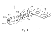
- FIG. 1 An embodiment of a receptacle terminal 1 shown in Fig. 1 which is formed by stamping out of a metal plate and bending, and is constructed by a contact section 11 into which a mating terminal is fitted and a crimp section 12 to which a wire is crimped. A rear end of the crimp section 12 is connected to a carrier section 13 which is used in a manufacturing process.
- the contact section 11 of the receptacle terminal 1 is in a substantially box shape having a fitting port 11a into which a male terminal is fitted, and the crimp section 12 of the receptacle terminal 1 includes a wire barrel 121 which holds a core wire of an electrical wire and an insulation barrel 122 which holds a coated portion of the electrical wire.
- Fig. 1 shows a state in which a locking section 1141, a bore 1142 and a guide section 1144 are included on a top surface of the contact section 11, and they will be described later.
- a description of the crimp section 12 and the carrier section 13 will be omitted since these elements are conventional in this field and therefore well known, and only the contact section 11 will be explained hereinafter.
- Fig. 2 shows an underside view of the receptacle terminal 1 having the contact section 11 formed by bending and stamping a metal plate into a substantially box shape.
- a link arm 112, a first protection arm 113 and a second protection arm 114 which comprise the contact section 11 will be described in detail later.
- the first protection arm 113 has a protection section 1131 which protects the link arm 112.
- the second protection arm 114 has a bent section 1143 which protects the link arm 112, a U-shaped section 1145 which forms a fitting port 11a (see Fig. 1), and a guide section 1144 which guides the male terminal to be fitted to the fitting port 11a.
- Figs. 3A and 3B are a front view and a side view of the receptacle terminal of this embodiment.
- Fig. 3A shows the receptacle terminal 1 as seen from the fitting port 11a side of the receptacle terminal 1, wherein a contact arm 111, having a contact point 111a for contacting a male terminal, and a moveable link arm 112 linked to the contact arm 111 at only the tip end portion, form an L-shape.
- Fig. 3B is a left side view of the receptacle terminal showing the second protection arm 114.
- Fig. 4 is a sectional view of the receptacle terminal of this embodiment.
- Fig. 4A shows a sectional view taken along the line A-A (see Fig. 3A) of the contact section 11 of the receptacle terminal 1
- Fig. 4B shows a sectional view taken along the line D-D (see Fig. 4A) of the contact section 11 of the receptacle terminal 1.
- the receptacle terminal 1 is formed by bending a metal plate into a substantially box shaped form while enfolding a portion corresponding to the contact arm 111, at an inside end portion of the metal plate, after performing a stamping operation on the metal plate.
- the contact arm 111 is further bent to incline toward the fitting port 11a from the rear of the contact section 11.
- the contact section 11 includes the contact arm 111 provided with the contact point 111a which contacts a male terminal.
- the link arm 112, to which a tip end portion of the contact arm 111 is connected, has a first edge 1121 extending along a fitting direction of the male terminal, and the contact arm 111 and the link arm 112 comprise a contact spring having an L-shaped section. Only the tip end portion of the contact arm 111 is connected to the link arm, all other parts of the contact arm 111 are not in contact with the link arm 112.
- the contact section 11 includes the first protection arm 113 which is adapted to oppose the contact arm 111, at the side where the link arm 112 is disposed, and to protect the contact spring.
- the second protection arm 114 includes a first surface 114a which is adapted to oppose the link arm 112 at the side where the contact arm 111 is disposed, and to protect the contact spring, and a second surface 114b which is adapted to oppose the first protection arm 113 with the contact arm 111 between the first protection arm 113 and the second surface 114b to protect the contact spring.
- the contact section 11 an area above the contact arm 111 is covered with the second surface 114b of the second protection arm 114 as shown in Fig. 4B.
- the second protection arm 114 includes the bent section 1143 which is bent to the side of the first edge 1121 of the link arm 112.
- the first protection arm 113 includes the protection section 1131 at the side of a second edge 1122 which is on an opposite side from the first edge 1121 of the link arm 112.
- a projection 1111 which determines the position of the contact arm 111 at the side of the crimp section 12 by being fitted into the bore 1142 provided in a border of the first surface 114a and the second surface 114b of the second protection arm 114, is included at the contact arm 111 at the side of the crimp section 12.
- a portion of the first protection arm 113 which opposes the contact point 111a provided at the contact arm 111, is raised to press a male terminal fitted therein against the contact point 111a more reliably.
- the first protection arm 113 and the first surface 114a of the second protection arm 114 perform the functions of a pair of contact springs of the prior art. Namely, the function of pressing the male terminal fitted therein against the other contact spring, and the function of a protection member which protects the contact spring and the contact arm 111. This is especially important for contact of a fitted male terminal, which is also protected by the second surface 114b of the second protection arm 114.
- the contact spring is sufficiently protected and a necessary contact pressure can be ensured between the receptacle terminal and the male terminal, whilst also minimising the external size.
- the link arm 112 is protected with respect to the direction to connect the first edge 1121 of the link arm 112 and the second edge 1122 on the opposite side of the first edge 1121 by the bent section 1143 and the protection section 1131.
- the locking section 1141 is formed as a cut and raised section on the second surface 114b of the second protection arm 114 on an opposing side from that of the contact arm 111. Consequently, even if the thickness of the second surface 114b of the second protection arm 114 is small, a necessary engagement margin can be ensured between the second protection arm 114 and a housing lance of a connector housing.
- Figs. 5A and 5B respectively show top and bottom perspective views of a receptacle terminal 2 of this embodiment.
- the receptacle terminal 2 comprises a contact section 21, into which a male terminal is fitted and contact with the male terminal is made, and a crimp section 22 to which an electrical wire is crimped.
- Equivalent elements of this embodiment are assigned with the same reference numerals and characters as the reference numerals and characters of corresponding elements in Fig. 1 to Figs. 4A and 4B.
- the difference between the contact section 11 of the receptacle terminal 1 of the first embodiment and the contact section 21 of the receptacle terminal 2 of the second embodiment is that the contact arm 111 which contacts the male terminal inclines downward towards the fitting port 11a from the back side of the contact section 11, whereas in the second embodiment, the contact arm 111 inclines downward to the back side of the contact section 21 from the fitting port 11a.
- the number of the locking sections 1141, for preventing the receptacle terminal 2 from falling off a connector housing in which the receptacle terminal 2 has been inserted, and the number of the bores 1142 provided in the border of the first surface 114a and the second surface 114b, are respectively increased to two.
- Fig. 5A shows the locking section 1141 included at the second surface 114b of the second protection arm 114, a projected section 1146 disposed behind the locking section 1141 in line with the locking section 1141, a bent section 1143 which protects the link arm 112 and is included at the end portion of the second surface 114b of the second protection arm 114, and the protection section 1131 included at the first protection arm 113.
- Fig. 5B shows the first protection arm 113 and the first surface 114a of the second protection arm 114, a recess 1132a which is provided in the vicinity of a center of the first protection arm 113. Also shown are two bores 1142, into which the projections 1111 (not shown) that position the contact arm 111 are fitted, are provided in the border of the first surface 114a and the second surface 114b.
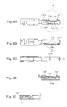
- Fig. 6A shows the contact arm 111 and the link arm 112, which comprise the contact spring, the bent section 1143 and the protection section 1131 which protects the link arm 112. Also shown are the locking section 1141 included at the second surface 114b of the second protection arm 114, and a projection 1132b which projects to an opposite side from the first protection arm 113 by the recess 1132a (see Fig. 6C) provided at the first protection arm 113.
- Fig. 6B shows two bores 1142 provided in the border of the first surface 114a and the second surface 114b of the second protection arm 114.
- Fig. 6B shows the projections 1111 of the contact arm 111 fitted into the two bores 1142.
- Fig. 6C shows the recess 1132a provided at the first protection arm 113.
- Fig. 6D and Fig. 6E respectively show a sectional view taken along the line E-E (see Fig. 5A) and the line F-F (see Fig. 5B) of the contact section 21 of the receptacle terminal 2
- Fig. 6D also shows the contact arm 111 inclined downward towards a back side of the contact section 21 from the fitting port 11a (see Fig. 4A), and the projection 1132b, which is provided to oppose the contact point 111a, and which makes contact with a side terminal more reliable.
- the projection 1132b which becomes the contact point with a mating male terminal, is provided on the same side as the crimp section 22. Therefore, as compared with the receptacle terminal 1 of the first embodiment provided with the contact point 111a on the fitting port 11a side, lower insertion of the mating male terminal is realized.
- Fig. 6E shows the contact spring comprising the contact arm 111 and the link arm 112.
- the contact spring can be protected and a necessary contact pressure can be ensured between the receptacle terminal and the male terminal while the external size is minimised.
- the bent section 1143 and the protection section 1131 can protect the link arm 112 with respect to the direction to connect the first edge 1121 of the link arm 112 and the second edge 1122 at the opposite side from this edge 1121.
- the locking section 1141 is formed as a cut and raised section on the second surface 114b of the second protection arm 114 on an opposing side from that of the contact arm 111. Consequently, even if the thickness of the second surface 114b of the second protection arm 114 is small, a necessary engagement margin can be ensured between the receptacle terminal and a housing lance of a connector housing. Furthermore, the locking section 1141 and the projected section 1146 which are longitudinally arranged in line are eccentrically formed, and thereby, a reverse insertion can be prevented.
- Fig. 7 shows a perspective view of a receptacle terminal 3 of this embodiment, corresponding to Fig. 5A showing the receptacle terminal 2 of the second embodiment.
- the difference between the receptacle terminal 3 of this embodiment and the receptacle terminal 2 of the second embodiment is that the length of a first bent section 112a between the link arm 112 and the first protection arm 113 is longer in the third embodiment than in the second embodiment. This point will be described and clarified hereinafter.
- Fig. 8 shows a part of a right side view of a receptacle terminal 3 of this embodiment, corresponding to the part encircled by the dotted line P shown in Fig. 6A of the second embodiment, where the length of the first bent section 112a is expressed by a dimension A, the length (width) of a root section 112b which is a root portion of the link arm 112 is expressed by a dimension C, and the length of a second bent section 112c on the second surface 114b side of the second protection arm 114 (see Fig. 4B) is expressed by a dimension B.
- the ratio of these dimensions A, B and C is 18:12:7, and as a result that the length of the first bent section 112a is made longer than the second bent section 112b as compared with the receptacle terminal 2 of the second embodiment.
- the first bent section 112a becomes a support point portion when the link arm 112 moves in an up and down direction, and as a result that the dimension of the first bent section 112a is made longer without changing the dimension of the second bent section 112c, and the contact pressure between the contact point 111a (see Fig. 6D) included at the contact arm 111 is made higher than the receptacle terminal 2 of the second embodiment without increasing the external size of the receptacle terminal. Therefore, in the receptacle terminal 3 of this embodiment, a proper contact pressure is obtained while miniaturization of the receptacle terminal is realized by optimizing the above described three dimensions.
- the projection 1132b which is the contact point with the mating male terminal is provided on the crimp section side as in the receptacle terminal of the second embodiment, and thereby, lower insertion of the mating male terminal is realized.
- the bent section 1143 included at the end portion of the second surface 114b of the second protection arm 114, the protection section 1131 included at the first protection arm 113, and the locking section 1141 for preventing the receptacle terminal from falling off after insertion into a connector housing are advantageous features of the present invention. However, with receptacle terminals which do not include some, or all of these features, the effect of the present invention is not decreased.
Landscapes
- Connector Housings Or Holding Contact Members (AREA)
- Coupling Device And Connection With Printed Circuit (AREA)
Applications Claiming Priority (2)
| Application Number | Priority Date | Filing Date | Title |
|---|---|---|---|
| JP2004205021 | 2004-07-12 | ||
| JP2005124546A JP4514645B2 (ja) | 2004-07-12 | 2005-04-22 | 雌型端子 |
Publications (2)
| Publication Number | Publication Date |
|---|---|
| EP1617521A1 true EP1617521A1 (de) | 2006-01-18 |
| EP1617521B1 EP1617521B1 (de) | 2010-09-08 |
Family
ID=35045451
Family Applications (1)
| Application Number | Title | Priority Date | Filing Date |
|---|---|---|---|
| EP05106327A Ceased EP1617521B1 (de) | 2004-07-12 | 2005-07-11 | Anschlussbuchse |
Country Status (4)
| Country | Link |
|---|---|
| US (1) | US7351122B2 (de) |
| EP (1) | EP1617521B1 (de) |
| JP (1) | JP4514645B2 (de) |
| DE (1) | DE602005023381D1 (de) |
Cited By (2)
| Publication number | Priority date | Publication date | Assignee | Title |
|---|---|---|---|---|
| WO2017140857A1 (fr) * | 2016-02-19 | 2017-08-24 | Delphi International Operations Luxembourg S.À R.L. | Contact électrique femelle avec barre de renfort interagissant avec la lame de contact |
| WO2017140858A1 (fr) * | 2016-02-19 | 2017-08-24 | Delphi International Operations Luxembourg S.À R.L. | Contact électrique femelle avec lame de contact élargie |
Families Citing this family (34)
| Publication number | Priority date | Publication date | Assignee | Title |
|---|---|---|---|---|
| TWD119869S1 (zh) | 2006-05-18 | 2007-11-11 | 太谷電子恩普股份有限公司 | 電性接觸件 |
| TWD130275S1 (zh) * | 2008-04-08 | 2009-08-11 | 股份有限公司 | 接點元件 |
| US7950972B1 (en) * | 2009-12-02 | 2011-05-31 | J. S. T. Corporation | Electrical female terminal |
| JP5841376B2 (ja) * | 2011-08-23 | 2016-01-13 | タイコエレクトロニクスジャパン合同会社 | 雌型端子 |
| ES2566360T3 (es) | 2012-04-12 | 2016-04-12 | Yazaki Europe Ltd | Terminal eléctrico |
| JP6124537B2 (ja) * | 2012-09-03 | 2017-05-10 | 矢崎総業株式会社 | メス端子 |
| US9284970B2 (en) * | 2012-09-14 | 2016-03-15 | Bal Seal Engineering, Inc. | Connector housings, use of, and method therefor |
| JP6410389B2 (ja) * | 2013-05-14 | 2018-10-24 | 日本端子株式会社 | 雌型端子 |
| EP3005485B1 (de) | 2013-06-07 | 2018-01-03 | FCI Asia Pte. Ltd. | Kabelverbinder |
| US9972932B2 (en) * | 2013-08-19 | 2018-05-15 | Fci Americas Technology Llc | Electrical connector with high retention force |
| US10230189B2 (en) * | 2013-12-03 | 2019-03-12 | Amphenol Fci Asia Pte Ltd | Connector and pin receiving contact for such a connector |
| JP6357334B2 (ja) * | 2014-03-28 | 2018-07-11 | 矢崎総業株式会社 | 圧着端子と電線の接続構造 |
| FR3027464B1 (fr) * | 2014-10-21 | 2018-03-23 | Aptiv Technologies Limited | Borne pour connecteur electrique a lame de contact renforcee |
| JP6540487B2 (ja) * | 2015-12-11 | 2019-07-10 | 住友電装株式会社 | 雌端子金具 |
| JP6536898B2 (ja) * | 2015-12-11 | 2019-07-03 | 住友電装株式会社 | 端子金具 |
| JP6422851B2 (ja) * | 2015-12-16 | 2018-11-14 | 矢崎総業株式会社 | 圧着端子の製造方法 |
| TWD176975S (zh) * | 2016-01-18 | 2016-07-11 | 百容電子股份有限公司 | 端子之部分 |
| WO2017139249A1 (en) * | 2016-02-08 | 2017-08-17 | Molex, Llc | Terminal fitting |
| EP3240114B1 (de) * | 2016-04-25 | 2019-01-23 | Aptiv Technologies Limited | Elektrische kontaktklemme und verfahren zur herstellung davon |
| JP1570826S (de) * | 2016-09-13 | 2017-03-06 | ||
| JP6543284B2 (ja) * | 2017-02-10 | 2019-07-10 | タイコエレクトロニクスジャパン合同会社 | 雌型コンタクト、及び、コンタクトの嵌合構造 |
| DE112018001099T5 (de) | 2017-03-01 | 2019-12-19 | Molex, Llc | Elektrischer Anschluss und Verbinderanordnung |
| JP6781934B2 (ja) * | 2017-04-26 | 2020-11-11 | 住友電装株式会社 | 端子 |
| KR102011845B1 (ko) * | 2017-07-12 | 2019-08-19 | 몰렉스 엘엘씨 | 포크인 커넥터 |
| JP1604439S (de) * | 2017-11-01 | 2018-05-21 | ||
| USD840942S1 (en) * | 2017-11-02 | 2019-02-19 | Vincent Paul DeVito | Terminal crimp socket |
| USD913942S1 (en) * | 2018-03-02 | 2021-03-23 | Molex, Llc | Connector terminal |
| CN115986449A (zh) | 2018-03-16 | 2023-04-18 | 富加宜(美国)有限责任公司 | 高密度电连接器 |
| JP7152993B2 (ja) * | 2019-07-18 | 2022-10-13 | 株式会社オートネットワーク技術研究所 | 端子、および端子付き電線 |
| JP7158349B2 (ja) * | 2019-07-18 | 2022-10-21 | 株式会社オートネットワーク技術研究所 | 端子、および端子付き電線 |
| CN112350092B (zh) * | 2019-08-08 | 2023-07-18 | 上海莫仕连接器有限公司 | 连接器及端子 |
| JP1680159S (ja) * | 2020-08-27 | 2021-03-01 | 端子金具 | |
| DE102021108272A1 (de) | 2021-03-31 | 2022-10-06 | Te Connectivity Germany Gmbh | Kontaktelement für einen elektrischen Stecker |
| USD1049044S1 (en) * | 2022-06-17 | 2024-10-29 | Inteva Products, Llc | Receptacle terminal |
Citations (2)
| Publication number | Priority date | Publication date | Assignee | Title |
|---|---|---|---|---|
| US4934965A (en) * | 1988-05-26 | 1990-06-19 | Kabelwerke Reinshagen Gmbh | Electrical connector with a spring cage receptacle |
| US6305992B1 (en) * | 1996-10-17 | 2001-10-23 | The Whitaker Corporation | Electrical connector having a housing and an electrical contact and electrical contact |
Family Cites Families (11)
| Publication number | Priority date | Publication date | Assignee | Title |
|---|---|---|---|---|
| GB8728575D0 (en) | 1987-12-07 | 1988-01-13 | Amp Gmbh | Electrical socket terminal |
| US4907990A (en) * | 1988-10-07 | 1990-03-13 | Molex Incorporated | Elastically supported dual cantilever beam pin-receiving electrical contact |
| US5188545A (en) * | 1990-06-05 | 1993-02-23 | Amp Incorporated | Electrical socket terminal |
| EP0650224B1 (de) * | 1991-06-03 | 1999-02-03 | The Whitaker Corporation | Elektrischer Kontakt |
| GB9424117D0 (en) * | 1994-11-28 | 1995-01-18 | Amp Gmbh | Receptacle contact for pressed screen contact pins |
| DE19612630C2 (de) * | 1995-03-30 | 2001-09-20 | Yazaki Corp | Steckbuchse und Verfahren zu deren Herstellung |
| US5681190A (en) * | 1995-05-23 | 1997-10-28 | Cardell Corporation | Torsional blade receptacle |
| EP0795930B1 (de) * | 1996-03-11 | 2002-07-17 | Molex Incorporated | Elektrische Aufnahmebuchse für Stift mit hoher Kontaktkraft |
| FR2749442B1 (fr) * | 1996-06-03 | 1998-07-10 | Framatome Connectors Int | Borne de contact electrique femelle a structure reforcee |
| JPH10134870A (ja) * | 1996-10-16 | 1998-05-22 | Whitaker Corp:The | リセプタクル型コンタクト |
| JP3502622B2 (ja) | 2001-12-18 | 2004-03-02 | 株式会社住化分析センター | 気体中の揮発性有機化合物量の簡易定量法 |
-
2005
- 2005-04-22 JP JP2005124546A patent/JP4514645B2/ja not_active Expired - Lifetime
- 2005-07-11 EP EP05106327A patent/EP1617521B1/de not_active Ceased
- 2005-07-11 DE DE602005023381T patent/DE602005023381D1/de not_active Expired - Lifetime
- 2005-07-12 US US11/180,748 patent/US7351122B2/en not_active Expired - Lifetime
Patent Citations (2)
| Publication number | Priority date | Publication date | Assignee | Title |
|---|---|---|---|---|
| US4934965A (en) * | 1988-05-26 | 1990-06-19 | Kabelwerke Reinshagen Gmbh | Electrical connector with a spring cage receptacle |
| US6305992B1 (en) * | 1996-10-17 | 2001-10-23 | The Whitaker Corporation | Electrical connector having a housing and an electrical contact and electrical contact |
Cited By (4)
| Publication number | Priority date | Publication date | Assignee | Title |
|---|---|---|---|---|
| WO2017140857A1 (fr) * | 2016-02-19 | 2017-08-24 | Delphi International Operations Luxembourg S.À R.L. | Contact électrique femelle avec barre de renfort interagissant avec la lame de contact |
| WO2017140858A1 (fr) * | 2016-02-19 | 2017-08-24 | Delphi International Operations Luxembourg S.À R.L. | Contact électrique femelle avec lame de contact élargie |
| FR3048134A1 (fr) * | 2016-02-19 | 2017-08-25 | Delphi Int Operations Luxembourg Sarl | Contact electrique femelle avec barre de renfort interagissant avec la lame de contact |
| FR3048133A1 (fr) * | 2016-02-19 | 2017-08-25 | Delphi Int Operations Luxembourg Sarl | Contact electrique femelle avec lame de contact elargie |
Also Published As
| Publication number | Publication date |
|---|---|
| JP2006054166A (ja) | 2006-02-23 |
| US7351122B2 (en) | 2008-04-01 |
| EP1617521B1 (de) | 2010-09-08 |
| US20060035538A1 (en) | 2006-02-16 |
| JP4514645B2 (ja) | 2010-07-28 |
| DE602005023381D1 (de) | 2010-10-21 |
Similar Documents
| Publication | Publication Date | Title |
|---|---|---|
| EP1617521B1 (de) | Anschlussbuchse | |
| US7938695B2 (en) | Terminal fitting | |
| US7993146B2 (en) | Electrical connector | |
| JP4368897B2 (ja) | コネクタ | |
| JP6342608B2 (ja) | 雌端子 | |
| US7179126B2 (en) | Electrical connector with improved terminals | |
| US20040171293A1 (en) | Electrical connector for a flat cable | |
| JP6316911B1 (ja) | コネクタ | |
| US20050191912A1 (en) | Female terminal fitting and a blank for a plurality of terminal fittings | |
| US20030220015A1 (en) | Terminal fitting and method of forming it | |
| US7273397B2 (en) | Electrical connector having flexible mating portion | |
| EP2416452A1 (de) | Anschlusskontakt | |
| US7255611B2 (en) | Connector | |
| JP3745318B2 (ja) | 電気コネクタ組立体 | |
| EP1689034A1 (de) | Anschlusskontakt , dazugehöriger Verbinder und Verfahren zur Herstellung | |
| US6629864B2 (en) | Electrical contact for plug-in connector | |
| EP3989369B1 (de) | Anschlussklemme | |
| CN110391530B (zh) | 阴端子 | |
| US11381009B2 (en) | Contact and connector | |
| JP7704805B2 (ja) | 端子 | |
| JP2003331970A (ja) | 接続端子 | |
| US7470127B2 (en) | Electrical connector assembly | |
| JP2026084443A (ja) | 電気接続端子 | |
| US20060141839A1 (en) | Electrical card connector | |
| US20180151972A1 (en) | Female electrical terminal |
Legal Events
| Date | Code | Title | Description |
|---|---|---|---|
| PUAI | Public reference made under article 153(3) epc to a published international application that has entered the european phase |
Free format text: ORIGINAL CODE: 0009012 |
|
| AK | Designated contracting states |
Kind code of ref document: A1 Designated state(s): AT BE BG CH CY CZ DE DK EE ES FI FR GB GR HU IE IS IT LI LT LU LV MC NL PL PT RO SE SI SK TR |
|
| AX | Request for extension of the european patent |
Extension state: AL BA HR MK YU |
|
| 17P | Request for examination filed |
Effective date: 20060629 |
|
| AKX | Designation fees paid |
Designated state(s): DE FR GB |
|
| 17Q | First examination report despatched |
Effective date: 20060831 |
|
| GRAP | Despatch of communication of intention to grant a patent |
Free format text: ORIGINAL CODE: EPIDOSNIGR1 |
|
| RAP1 | Party data changed (applicant data changed or rights of an application transferred) |
Owner name: TYCO ELECTRONICS JAPAN G.K. |
|
| GRAS | Grant fee paid |
Free format text: ORIGINAL CODE: EPIDOSNIGR3 |
|
| GRAA | (expected) grant |
Free format text: ORIGINAL CODE: 0009210 |
|
| AK | Designated contracting states |
Kind code of ref document: B1 Designated state(s): DE FR GB |
|
| REG | Reference to a national code |
Ref country code: GB Ref legal event code: FG4D |
|
| REF | Corresponds to: |
Ref document number: 602005023381 Country of ref document: DE Date of ref document: 20101021 Kind code of ref document: P |
|
| PLBE | No opposition filed within time limit |
Free format text: ORIGINAL CODE: 0009261 |
|
| STAA | Information on the status of an ep patent application or granted ep patent |
Free format text: STATUS: NO OPPOSITION FILED WITHIN TIME LIMIT |
|
| 26N | No opposition filed |
Effective date: 20110609 |
|
| REG | Reference to a national code |
Ref country code: DE Ref legal event code: R097 Ref document number: 602005023381 Country of ref document: DE Effective date: 20110609 |
|
| REG | Reference to a national code |
Ref country code: FR Ref legal event code: PLFP Year of fee payment: 12 |
|
| REG | Reference to a national code |
Ref country code: FR Ref legal event code: PLFP Year of fee payment: 13 |
|
| REG | Reference to a national code |
Ref country code: FR Ref legal event code: PLFP Year of fee payment: 14 |
|
| PGFP | Annual fee paid to national office [announced via postgrant information from national office to epo] |
Ref country code: FR Payment date: 20180612 Year of fee payment: 14 |
|
| PGFP | Annual fee paid to national office [announced via postgrant information from national office to epo] |
Ref country code: DE Payment date: 20180626 Year of fee payment: 14 |
|
| PGFP | Annual fee paid to national office [announced via postgrant information from national office to epo] |
Ref country code: GB Payment date: 20180711 Year of fee payment: 14 |
|
| REG | Reference to a national code |
Ref country code: DE Ref legal event code: R119 Ref document number: 602005023381 Country of ref document: DE |
|
| GBPC | Gb: european patent ceased through non-payment of renewal fee |
Effective date: 20190711 |
|
| PG25 | Lapsed in a contracting state [announced via postgrant information from national office to epo] |
Ref country code: GB Free format text: LAPSE BECAUSE OF NON-PAYMENT OF DUE FEES Effective date: 20190711 Ref country code: DE Free format text: LAPSE BECAUSE OF NON-PAYMENT OF DUE FEES Effective date: 20200201 |
|
| PG25 | Lapsed in a contracting state [announced via postgrant information from national office to epo] |
Ref country code: FR Free format text: LAPSE BECAUSE OF NON-PAYMENT OF DUE FEES Effective date: 20190731 |