EP1621948B1 - Appareil et procédé pour appeler un robot mobile - Google Patents
Appareil et procédé pour appeler un robot mobile Download PDFInfo
- Publication number
- EP1621948B1 EP1621948B1 EP20050000110 EP05000110A EP1621948B1 EP 1621948 B1 EP1621948 B1 EP 1621948B1 EP 20050000110 EP20050000110 EP 20050000110 EP 05000110 A EP05000110 A EP 05000110A EP 1621948 B1 EP1621948 B1 EP 1621948B1
- Authority
- EP
- European Patent Office
- Prior art keywords
- mobile robot
- signal
- remote controller
- ultrasonic
- distance
- Prior art date
- Legal status (The legal status is an assumption and is not a legal conclusion. Google has not performed a legal analysis and makes no representation as to the accuracy of the status listed.)
- Ceased
Links
Images


Classifications
-
- G—PHYSICS
- G05—CONTROLLING; REGULATING
- G05D—SYSTEMS FOR CONTROLLING OR REGULATING NON-ELECTRIC VARIABLES
- G05D1/00—Control of position, course, altitude or attitude of land, water, air or space vehicles, e.g. using automatic pilots
- G05D1/02—Control of position or course in two dimensions
- G05D1/021—Control of position or course in two dimensions specially adapted to land vehicles
- G05D1/0231—Control of position or course in two dimensions specially adapted to land vehicles using optical position detecting means
- G05D1/0242—Control of position or course in two dimensions specially adapted to land vehicles using optical position detecting means using non-visible light signals, e.g. IR or UV signals
-
- A—HUMAN NECESSITIES
- A47—FURNITURE; DOMESTIC ARTICLES OR APPLIANCES; COFFEE MILLS; SPICE MILLS; SUCTION CLEANERS IN GENERAL
- A47L—DOMESTIC WASHING OR CLEANING; SUCTION CLEANERS IN GENERAL
- A47L9/00—Details or accessories of suction cleaners, e.g. mechanical means for controlling the suction or for effecting pulsating action; Storing devices specially adapted to suction cleaners or parts thereof; Carrying-vehicles specially adapted for suction cleaners
- A47L9/28—Installation of the electric equipment, e.g. adaptation or attachment to the suction cleaner; Controlling suction cleaners by electric means
-
- A—HUMAN NECESSITIES
- A47—FURNITURE; DOMESTIC ARTICLES OR APPLIANCES; COFFEE MILLS; SPICE MILLS; SUCTION CLEANERS IN GENERAL
- A47L—DOMESTIC WASHING OR CLEANING; SUCTION CLEANERS IN GENERAL
- A47L11/00—Machines for cleaning floors, carpets, furniture, walls, or wall coverings
-
- G—PHYSICS
- G05—CONTROLLING; REGULATING
- G05D—SYSTEMS FOR CONTROLLING OR REGULATING NON-ELECTRIC VARIABLES
- G05D1/00—Control of position, course, altitude or attitude of land, water, air or space vehicles, e.g. using automatic pilots
- G05D1/0011—Control of position, course, altitude or attitude of land, water, air or space vehicles, e.g. using automatic pilots associated with a remote control arrangement
- G05D1/0022—Control of position, course, altitude or attitude of land, water, air or space vehicles, e.g. using automatic pilots associated with a remote control arrangement characterised by the communication link
Definitions
- the present invention relates to a mobile robot and, more particularly, to an apparatus and method for calling a mobile robot.
- a mobile robot is a device for automatically cleaning an area by sucking foreign substances such as dust from the floor while moving in a room (e.g., a living room) of a house by itself without user's manipulation.
- the robot cleaner discriminates a distance from itself to an obstacle such as furniture, office supplies or a wall in a cleaning area through a distance sensor and selectively controls a motor for rotating its left wheel and a motor for rotating its right wheel according to the discriminated distance to thereby change its direction and automatically clean the cleaning area.
- the robot cleaner performs the cleaning operation while travelling in the cleaning area through map information stored in an internal storage unit.
- the robot cleaner includes a gyro sensor for sensing a direction of the robot cleaner, an encoder for determining a traveling distance by sensing the number of times of rotation of the wheel of the robot cleaner; an ultrasonic sensor for sensing a distance between the robot cleaner, a target; and an infrared ray sensor for sensing an obstacle, and other numerous sensors.
- the conventional robot cleaner has shortcomings in that because numerous high-priced sensors are installed to perform cleaning by precisely traveling along a pre-set cleaning path, its internal structure is complicated and fabrication cost increases.
- a robot cleaner has been developed to perform cleaning by traveling along an arbitrary cleaning path in a random manner.
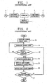
- Figure 1 is a block diagram showing the construction of the traveling device of a robot cleaner in accordance with a conventional art.
- the traveling device of a conventional robot cleaner includes: an obstacle sensing unit 1 for sensing an obstacle based on an impact amount generated when a robot cleaner going straight ahead in a specific area collides with the obstacle and generating an obstacle sense signal; a controller for stopping traveling of the robot cleaner based on the obstacle sense signal generated by the obstacle sensing unit 1 , generating a random angle randomly, and generating a control signal for rotating the robot cleaner according to the random angle; a left motor driving unit 3 for rotating a left motor (ML) 5 of the robot cleaner at a certain speed according to the control signal of the controller 2; and a right motor driving unit 4 for rotating a right motor (MR) 6 of the robot cleaner at a certain speed according to the control signal of the controller 2.
- an obstacle sensing unit 1 for sensing an obstacle based on an impact amount generated when a robot cleaner going straight ahead in a specific area collides with the obstacle and generating an obstacle sense signal
- a controller for stopping traveling of the robot cleaner based on the obstacle sense signal generated by the obstacle sensing unit 1 ,
- Figure 2 is a flow chart of a method for traveling a robot cleaner in accordance with the conventional art.
- step S1 when a user inputs a cleaning command signal (step S1), the controller 2 generates a control signal to make the rotation speed of the left motor 5 and the right motor 6 equal in order to making the robot cleaner go straight ahead, and simultaneously outputs the control signal to the left motor driving unit 3 an the right motor driving unit 4 (step S2).
- the left motor driving unit 3 rotates the left motor 5 according to the control signal of the controller.
- the right motor driving unit 4 rotates the right motor 6 according to the control signal of the controller 2. Namely, as the left and right motors 5 and 6 are simultaneously rotated, the robot cleaner goes straight ahead.
- the obstacle sensing unit senses an obstacle based on an amount of impact generated when the robot cleaner collides with the obstacle, generates an obstacle sense signal, and applies the obstacle sense signal to the controller 2 (step S3). If the obstacle sense signal is not generated, the robot cleaner continuously performs cleaning operation.
- the controller 2 stops traveling of the robot cleaner according to the obstacle sense signal, generates a random angle randomly (step S4), generates a control signal for rotating the robot cleaner according to the random angle, and then outputs the generated control signal to the left and right motor driving units 3 and 4.
- the left motor driving unit 3 rotates the left motor 5 according to the control signal of the controller 2
- the right motor driving unit 4 rotates the right motor 6 according to the control signal of the controller.
- the direction of the robot cleaner can be changed to a random angle (step S5).
- step S6 the controller allows the robot cleaner to go straight ahead.
- step S7 the controller terminates the cleaning operation (step S7). If the cleaning operation of the robot cleaner is not completed, the controller allows the robot cleaner to repeatedly perform the cleaning operation.
- the conventional robot cleaner has the problem that the user should personally pick up the robot cleaner and move it to a different cleaning space or a robot cleaner depository.
- document US2004/0085222 discloses a remote controller for remotely controlling a robot vehicle, wherein the controller comprises a joystick that can be used to make the robot vehicle move towards the user.
- an object of the present invention is to provide an apparatus and method for calling a mobile robot capable of making a mobile robot, such as a robot cleaner, by itself moved to a specific place when a user calls the mobile robot from the specific place, so that the user does not need to personally pick up the mobile robot to move it to a desired place, thereby enhancing user's convenience.
- an apparatus for calling a mobile robot including: a generator installed at a remote controller, and generating an RF signal and infrared signal for calling a mobile robot when a call signal is inputted by a user; and a controller installed at the mobile robot, calculating a direction of the remote controller based on a position of an infrared ray receiver that receives the infrared signal when an RF signal is received, rotating the mobile robot in the calculated direction, and then making the mobile robot to go straight ahead.
- an apparatus for calling a mobile robot including: a generator installed at a remote controller, receiving a call signal from a user, and generating an RF signal and ultrasonic signal for calling a mobile robot; and a controller installed at the mobile robot, calculating a direction of the remote controller based on a position of an ultrasonic receiver which has received the ultrasonic signal when the RF signal was received, calculating a distance between the remote controller and the mobile robot based on time when the ultrasonic signal reaches the ultrasonic receiver, rotating the mobile robot in the calculated direction, and then making the mobile robot go straight ahead as long as the calculated distance.
- an apparatus for calling a mobile robot including: an RF generator installed at a remote controller and generating an RF signal for calling a mobile robot when a call signal is inputted by a user; an infrared ray generator installed at the remote controller and generating an infrared signal for indicating a direction of the remote controller when the call signal is inputted; an RF receiver installed at the mobile robot and receiving the RF signal generated from the RF generator; a plurality of infrared ray receivers installed at the mobile robot and receiving the infrared signal generated from the infrared ray generator; and a controller installed at the mobile robot, recognizing a direction of the remote controller based on a position of an infrared ray receiver that has received the infrared signal, among the plurality of infrared ray receivers, when the RF receiver receives the RF signal, rotating the mobile robot in the recognized direction, and making the mobile robot go straight ahead.
- an apparatus for calling a mobile robot including: an RF generator installed at a remote controller and generating an RF signal for calling a mobile robot when a call signal is inputted by a user; an ultrasonic wave generator installed at the remote controller and generating an ultrasonic signal for indicating a distance between the mobile robot and the remote controller when the call signal is inputted; an RF receiver installed at the mobile robot and receiving the RF signal generated from the RF generator; a plurality of ultrasonic wave receivers installed at the mobile robot and receiving the ultrasonic signal generated from the ultrasonic wave generator; and a controller installed at the mobile robot, calculating a direction of the remote controller and a distance between the mobile robot and the remote controller based on a position of an ultrasonic wave receiver that has received the ultrasonic signal, among the plurality of ultrasonic wave receivers, when the RF receiver receives the RF signal, moving the mobile robot to the remote controller based on the calculated direction and distance value.
- a method for calling a mobile robot including: a step in which when a call signal is inputted to a remote controller, an RF signal and an infrared signal for calling a mobile robot are generated through the remote controller; a step in which when the RF signal is received by the mobile robot, an operation mode of the mobile robot is switched to a call mode and a direction of the remote controller is calculated based on a position of an infrared ray receiver that has received the infrared signal, among a plurality of infrared ray receivers installed at the mobile robot; and a step in which a front side of the mobile robot is rotated in the calculated direction and then the mobile robot is allowed to go straight ahead.
- a method for calling a mobile robot including: a step in which when a call signal is inputted to a remote controller, an RF signal and an ultrasonic signal for calling a mobile robot are simultaneously generated through the remote controller; a step in which when the RF signal is received by an RF receiver of the mobile robot, an operation mode of the mobile robot is changed to a call mode and then a direction of the remote controller is calculated based on a position of an ultrasonic save receiver, among a plurality of ultrasonic wave receivers installed at the mobile robot, that has received the ultrasonic signal; a step in which a distance between the remote controller and the mobile robot is calculated based on a time when the ultrasonic signal reaches the ultrasonic wave receiver; a step in which a front side of the mobile robot is rotated in the calculated direction; and a step in which the mobile robot is allowed to go straight ahead as long as the calculated distance value.
- Figure 3 is a block diagram showing an apparatus for calling a mobile robot in accordance with a first embodiment of the present invention.
- an apparatus for calling a mobile robot in accordance with a first embodiment of the present invention includes: an RF generator 101 installed at a remote controller 100 and generating an RF signal for calling a mobile robot 200 when a call signal is inputted by a user; an infrared ray generator 102 installed at the remote controller 100 and generating an infrared signal for indicating a direction of the remote controller 100 when the call signal is inputted; an RF receiver 201 installed at the mobile robot 200 and receiving the RF signal generated from the RF generator 101; a plurality of infrared ray receivers 203-1 ⁇ 203-N installed at the mobile robot 200 and receiving the infrared signal generated from the infrared ray generator 102; and a controller 202 installed at the mobile robot 200, recognizing a direction of the remote controller 100 based on a position of an infrared ray receiver that has received the infrared signal, among the plurality of infrared ray receivers 203-1 ⁇ 203-N, when
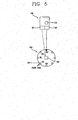
- Figure 4 is a schematic view shown a plurality of infrared ray receivers installed at the mobile robot in accordance with the first embodiment of the present invention.
- the plurality of infrared ray receivers 203-1-203-N are preferably installed an certain intervals at an outer circumferential surface of the mobile robot 200 based the front side of the mobile robot 200, of which the first infrared ray receiver IR1 is preferably installed at the front side of the mobile robot 200 in order to set a reference angle (e.g., 0°).
- a reference angle e.g., 0°
- Figure 5 is a schematic view showing a process of transmitting an RF signal and an infrared signal from a remote controller to the mobile robot in accordance with the first embodiment of the present invention.
- a user directs a remote controller 100 toward the mobile robot 200 and presses a call button 103 installed on the remote controller 100. Then, an RF signal and an infrared signal are transmitted in the direction of the mobile robot 200. At this time, when the direction of the remote controller 100 and the direction of the mobile robot 200 correspond to each other, the infrared signal is received by a fourth infrared ray receiver IR4.
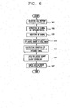
- Figure 6 is a flow chart of a method for calling the mobile robot in accordance with the first embodiment of the present invention.
- the RF generator 101 installed at the remote controller 100 generates an RF signal for calling the mobile robot 200 and transmits the generated RF signal to the RF receiver 201 installed in the mobile robot 200.
- the infrared ray generator 102 installed in the remote controller 100 When the user selects the call button 103 of the remote controller 100 (step S11), the infrared ray generator 102 installed in the remote controller 100 generates an infrared signal for informing about its direction and transmits the generated infrared signal in the direction of the mobile robot 200 (step S12).
- the direction of the infrared ray generator 102 means the direction of the remote controller 100.
- the RF receiver 201 installed in the mobile robot 200 receives the RF signal transmitted from the RF generator 101.
- an infrared ray receiver positioned in the same direction as the infrared ray generator 102 e.g., a fourth infrared ray receiver IR3 among the plurality of infrared ray receivers 203-1 ⁇ 203-N installed at the mobile robot 200 receives the infrared signal transmitted from the infrared ray generator 102.
- the controller 202 switches an operation mode of the mobile robot 200 to a call mode (step S14).
- the controller 202 calculates a direction of the remote controller 100 based on a position of an infrared ray receiver (e.g., the fourth infrared ray receiver IR3) that has received the infrared signal among the plurality of infrared ray signals 203-1 ⁇ 203-N (step S15).
- an infrared ray receiver e.g., the fourth infrared ray receiver IR3
- the controller 202 can include a storing unit (not shown) for storing pre-set position numbers for discriminating a position of the plurality of infrared ray receivers 203-1 ⁇ 203-N and determine a position of the infrared ray receiver that has received the infrared signal based on the pre-set position number of the infrared ray receiver.
- a storing unit not shown for storing pre-set position numbers for discriminating a position of the plurality of infrared ray receivers 203-1 ⁇ 203-N and determine a position of the infrared ray receiver that has received the infrared signal based on the pre-set position number of the infrared ray receiver.
- the controller 202 can recognize that the remote controller 100 is positioned in the direction of 45° of the front side of the mobile robot 200 because the angle between the first infrared ray receiver IR0 and the fourth infrared ray receiver IR3 is 135°.
- the position number of the first infrared ray receiver is 0, preferably, the position number of the second infrared ray receiver is set as 1, the position number of the third infrared ray receiver is set as 2 and the position number of the fourth infrared ray receiver is set as 3, and the position number of the Nth infrared ray receiver is set as N.
- the controller 202 calculates the direction of the remote controller 100 based on the position of the infrared ray receiver that has received the infrared signal, namely, the fourth infrared ray receiver IR3, rotates the front side of the mobile robot 200 in the direction of the remote controller 100 (e.g., 135°) (step S16), and then, allows the mobile robot to go straight ahead (step S17).
- the middle point is calculated as a direction of the remote controller 100.
- the middle value of 4 is preferably substituted for the 'x' value and if the infrared ray receivers whose position numbers are 5 to 8 simultaneously receive the infrared signal, a middle value of 6 and 7 is preferably substituted for the 'x' value.
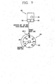
- Figure 7 is an exemplary view showing a process that a front side of the mobile robot is rotated in a direction of the remote controller and then the mobile robot is allowed to go straight ahead in accordance with the present invention.
- an angle between adjacent infrared ray receivers e.g., the first and second infrared ray receivers IR0 and IR1
- the infrared ray receiver that has received the infrared signal is the fourth infrared ray receiver IR3 among the plurality of infrared ray receivers 203-1 ⁇ 203-N
- the controller 202 rotates the mobile robot 200 as much as 135° and then makes the mobile robot 200 go straight ahead.
- the angle between the first and fourth infrared ray receivers IR0 and IR3 is 135°, when the mobile robot 200 is rotated as much as 135°, the front side of the mobile robot faces the remote controller 100. Accordingly, when the mobile robot 200 is rotated 135° and then allowed to go straight ahead, it would reach a point where the remote controller 100 exists.
- the user turns off the call button 103 to stop the mobile robot 200.
- the controller 202 moves the mobile robot 200 in the direction of the remote controller, and when the user turns off the call button 103, the controller stops the mobile robot 200.
- the mobile robot 200 follows the user. In this case, the direction of the remote controller 100 preferably faces the mobile robot 200.
- the mobile robot 200 can be easily moved and rotated by controlling the left and right motor of the mobile robot 200, detained descriptions of which are thus omitted.
- the apparatus for calling the mobile robot capable of automatically stopping the mobile robot 200 when it reaches the remote controller 100 by calculating the distance between the remote controller 100 and the mobile robot 200 as well as the direction of the remote controller 100 by using an ultrasonic wave generator and ultrasonic wave receivers, rather than using the infrared ray generator 102 and the plurality of infrared ray receivers 203-1 ⁇ 203-N.
- Figure 8 is a block diagram showing the construction of an apparatus for calling a mobile robot in accordance with a second embodiment of the present invention.
- an apparatus for calling a mobile robot in accordance with a second embodiment of the present invention includes: an RF generator 301 installed at a remote controller 300 and generating an RF signal for calling a mobile robot 400 when a call signal is inputted by a user; an ultrasonic wave generator 302 installed at the remote controller 300 and generating an ultrasonic signal for indicating a distance between the mobile robot 400 and the remote controller 300 when the call signal is inputted; an RF receiver 401 installed at the mobile robot 400 and receiving the RF signal generated by the RF generator 301; a plurality of ultrasonic wave receivers 403-1 ⁇ 403-N installed at the mobile robot 400 and receiving the ultrasonic signal generated from the ultrasonic wave generator 302; and a controller 402 installed at the mobile robot 400, recognizing a direction of the remote controller 300 based on the position of an ultrasonic wave receiver that has received the ultrasonic signal among the plurality of ultrasonic wave receivers 403-1 ⁇ 403-N when the RF signal is received by
- the ultrasonic wave generator 302 and the plurality of ultrasonic wave receivers 403-1 ⁇ 403-N are installed at the mobile robot 400 in the same manner as the infrared ray generator 102 and the plurality of infrared ray receivers 203-1 ⁇ 203-N as shown in Figures 4 , 5 and 7 .
- Figure 9 is a flow chart of a method for calling the mobile robot in accordance with the second embodiment of the present invention.
- the RF generator 301 installed at the remote controller 300 generates an RF signal for calling the mobile robot 400 and transmits the generated RF signal to the RF receiver 401 of the mobile robot 400 (step S22).
- the ultrasonic wave generator 302 When the user selects the call button 103 of the remote controller 300 (step S21), the ultrasonic wave generator 302 generates an ultrasonic signal for informing about a direction of the remote controller 300 and a distance between the remote controller 300 and the mobile robot 400 and transmits the generated ultrasonic signal in the direction of the mobile robot 400 (step S22).
- the RF receiver 401 installed at the mobile robot 400 receives the RF signal transmitted from the RF generator 301 (step S23). At this time, the ultrasonic signal generated by the ultrasonic wave generator 302 is received by one or more ultrasonic wave receivers among the plurality of ultrasonic wave receivers 403-1 ⁇ 403-N.
- the controller 402 switches an operation mode of the mobile robot 400 to a call mode (step S24).
- the controller 402 calculates a direction of the remote controller 300 based on the position of the ultrasonic wave receiver that has received the ultrasonic signal.
- the controller 402 detects time when the ultrasonic signal has reached the ultrasonic wave receiver and then calculates the distance between the mobile robot 400 and the remote controller 300 based on the detected time (step S25).
- the controller 402 rotates a front side of the mobile robot 400 in the calculated direction (in the direction of the remote controller) (step S26) and then makes the mobile robot 400 go straight ahead as long as the calculated distance value. Namely, the controller 402 rotates the front side of the mobile robot 400 in the calculated direction (step S26) and then makes the mobile robot 400 go straight ahead as long as the calculated distance value (step S27) by controlling left and right motors of the mobile robot 400.
- the controller 402 can include a storing unit (not shown) for storing a pre-set position number for discriminating the plurality of ultrasonic wave receivers 403-1 ⁇ 403-N and determine a position of an ultrasonic wave receiver that has received the ultrasonic signal based on the position number of the ultrasonic wave receiver.
- a storing unit (not shown) for storing a pre-set position number for discriminating the plurality of ultrasonic wave receivers 403-1 ⁇ 403-N and determine a position of an ultrasonic wave receiver that has received the ultrasonic signal based on the position number of the ultrasonic wave receiver.
- a process of calculating the direction of the remote controller 300 is the same as in the first embodiment of the present invention, descriptions of which are thus omitted.
- the controller 402 detects time when the ultrasonic signal reaches one or more ultrasonic wave receivers after being generated from the ultrasonic wave generator 302 of the remote controller 300 based on point when an RF signal is generated as a reference, and calculates a distance between the mobile robot 400 and the remote controller 300 based the detected time.
- the controller 402 obtains a distance between the ultrasonic wave receiver (e.g., 403-1) that has received the ultrasonic signal and the remote controller 300 based the time when the ultrasonic signal reached the ultrasonic wave receiver, and adds a semidiameter of the mobile robot 400 to the obtained distance value, thereby accurately calculating an actual distance between the mobile robot 400 and the remote controller 300.
- the controller 402 calculates a distance between each ultrasonic wave receiver and the remote controller 300 based on time when the ultrasonic signal reaches the two or more ultrasonic wave receivers, and then, calculates an actual distance between the mobile robot 400 and the remote controller 300 through trigonometric measurement based on each calculated distance value.
- the apparatus for calling the mobile robot can be applied to various moving apparatus as well as the mobile robot.
- the apparatus and method for calling a mobile robot in accordance with the present invention have many advantages.
- the mobile robot can move by itself to the specific space, thereby enhancing users' convenience. For example, by moving the mobile robot such as a robot cleaner to a desired place (a cleaning space or a mobile robot depository) through the remote controller, the user does not need to be troubled by picking up the mobile robot and moving it to the desired place.
- a desired place a cleaning space or a mobile robot depository
Landscapes
- Engineering & Computer Science (AREA)
- Physics & Mathematics (AREA)
- General Physics & Mathematics (AREA)
- Automation & Control Theory (AREA)
- Aviation & Aerospace Engineering (AREA)
- Radar, Positioning & Navigation (AREA)
- Remote Sensing (AREA)
- Electromagnetism (AREA)
- Mechanical Engineering (AREA)
- Control Of Position, Course, Altitude, Or Attitude Of Moving Bodies (AREA)
- Electric Vacuum Cleaner (AREA)
- Manipulator (AREA)
- Selective Calling Equipment (AREA)
- Measurement Of Velocity Or Position Using Acoustic Or Ultrasonic Waves (AREA)
Claims (16)
- Dispositif comprenant un générateur (101, 102) installé au niveau d'une télécommande (100), un contrôleur (202) installé au niveau d'un robot mobile (200), calculant une direction de la télécommande (100), faisant tourner le robot mobile (200) dans la direction calculée, puis faisant avancer le robot mobile (200) tout droit vers l'avant, caractérisé en ce que :le générateur (101, 102) génère un signal RF et un signal infrarouge pour appeler le robot mobile (200) lorsqu'un signal d'appel est entré par un utilisateur en appuyant sur un bouton (103), dans lequel la direction de la télécommande (100) est calculée sur la base d'une position d'un récepteur de rayons infrarouges ayant reçu le signal infrarouge, parmi une pluralité de récepteurs de rayons infrarouges (203) installés au niveau du robot mobile (200) lorsque le signal RF est reçu.
- Dispositif comprenant un générateur (301, 302) installé au niveau d'une télécommande (300), un contrôleur (402) installé au niveau d'un robot mobile (400) calculant une direction de la télécommande (300), calculant une distance entre la télécommande (300) et le robot mobile (400), faisant tourner le robot mobile (400) dans la direction calculée, puis faisant avancer le robot mobile (400) tout droit vers l'avant, le long de la direction calculée sur toute la distance calculée, caractérisé en ce que :le générateur (301, 302) génère un signal RF et un signal ultrasonore pour appeler le robot mobile (400) lorsqu'un signal d'appel est entré par un utilisateur en appuyant sur un bouton (103), dans lequel la direction de la télécommande (300) est calculée sur la base d'une position d'un récepteur d'ultrasons ayant reçu le signal ultrasonore parmi une pluralité de récepteurs d'ultrasons (403) installés au niveau du robot mobile (400) lorsque le signal RF a été reçu, la distance entre la télécommande (300) et le robot mobile (400) est calculée sur la base du temps lorsque le signal ultrasonore atteint le récepteur d'ultrasons, et dans lequel le robot mobile (400) couvre une distance aussi longue que la distance calculée.
- Dispositif selon la revendication 1, dans lequel le contrôleur (202) fait tourner le côté avant du robot mobile (200) dans la direction calculée, puis fait avancer le robot mobile (200) tout droit vers l'avant, le long de la direction calculée.
- Dispositif selon la revendication 3, dans lequel le contrôleur (202) calcule la direction (y) de la télécommande (100) à l'aide de l'équation ci-dessous :
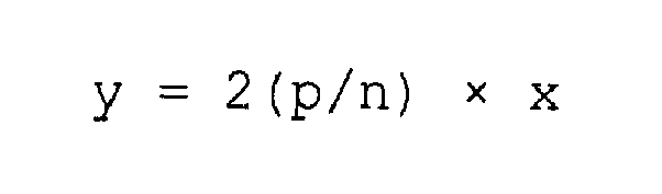
où 'n' est le nombre total de la pluralité de récepteurs de rayons infrarouges (203) installés au niveau du robot mobile (200), et 'x' est le numéro de position du récepteur de rayons infrarouges ayant reçu le signal infrarouge généré depuis le générateur (102). - Procédé pour l'appel d'un robot mobile comprenant :une étape dans laquelle, lorsqu'un signal d'appel est entré dans une télécommande (100) par un utilisateur en appuyant sur un bouton (103), un signal RF et un signal infrarouge pour l'appel d'un robot mobile (200) sont générés par le biais de la télécommande (100) ;une étape dans laquelle, lorsque le signal RF est reçu par le robot mobile (200), un mode de fonctionnement du robot mobile (200) est commuté vers un mode d'appel et une direction de la télécommande (100) est calculée sur la base d'une position d'un récepteur de rayons infrarouges ayant reçu le signal infrarouge, parmi une pluralité de récepteurs de rayons infrarouges (203) installés au niveau du robot mobile (200) ; etune étape dans laquelle un côté avant du robot mobile (200) est tourné dans la direction calculée, puis le robot mobile (200) peut se déplacer tout droit vers l'avant, le long de la direction calculée.
- Procédé selon la revendication 5, dans lequel la direction (y) de la télécommande (100) est calculée à l'aide de l'équation ci-dessous :

où 'n' est le nombre total de la pluralité de récepteurs de rayons infrarouges (203) installés au niveau du robot mobile (200), et 'x' est le numéro de position du récepteur de rayons infrarouges ayant reçu le signal infrarouge. - Dispositif selon la revendication 2, dans lequel le contrôleur (402) détecte le moment où le signal ultrasonore atteint le récepteur d'onde ultrasonore après avoir été généré depuis le générateur d'onde ultrasonore (302) sur la base du moment où le signal RF est généré, et calcule une distance entre le robot mobile (400) et la télécommande (300) sur la base du moment détecté.
- Dispositif selon la revendication 7, dans lequel le contrôleur (402) comprend une unité de stockage pour le stockage d'un numéro de position préréglé pour la discrimination des récepteurs d'onde ultrasonore (403), et calcule une direction de la télécommande (300) sur la base de la position du récepteur d'onde ultrasonore ayant reçu le signal ultrasonore.
- Dispositif selon la revendication 7, dans lequel, lorsqu'un récepteur d'onde ultrasonore reçoit le signal ultrasonore, le contrôleur (402) calcule une distance entre le récepteur d'onde ultrasonore ayant reçu le signal ultrasonore et la télécommande (300) sur la base du moment où le signal ultrasonore a atteint le récepteur d'onde ultrasonore, et ajoute un semi-diamètre du robot mobile (400) à la valeur de la distance calculée, calculant ainsi avec précision une distance effective entre le robot mobile (400) et la télécommande (300).
- Dispositif selon la revendication 7, dans lequel, lorsque le signal ultrasonore est reçu par deux récepteurs d'ondes ultrasonores (403) ou plus, le contrôleur (402) calcule une distance entre le robot mobile (400) et la télécommande (300) sur la base du moment où le signal ultrasonore a atteint les deux récepteurs d'ondes ultrasonores (403) ou plus, puis calcule une distance effective entre le robot mobile (400) et la télécommande (300) à l'aide d'une mesure trigonométrique basée sur chaque valeur de distance calculée.
- Dispositif selon la revendication 10, dans lequel le contrôleur (402) calcule la distance entre le récepteur d'onde ultrasonore et le générateur d'onde ultrasonore (302) à l'aide de l'équation ci-dessous :

où 340 [m/sec] est une vitesse du son, T1 est le moment où le signal ultrasonore est reçu et T2 est le moment où le signal ultrasonore est généré après réception du signal RF. - Procédé pour l'appel d'un robot mobile comprenant :une étape dans laquelle, lorsqu'un signal d'appel est entré dans une télécommande (300) par un utilisateur en appuyant sur un bouton (103), un signal RF et un signal ultrasonore pour l'appel d'un robot mobile (400) sont générés en même temps par le biais de la télécommande (300) ;une étape dans laquelle, lorsque le signal RF est reçu par un récepteur RF (401) du robot mobile (400), un mode de fonctionnement du robot mobile (400) est changé vers un mode d'appel, puis une direction de la télécommande (300) est calculée sur la base d'une position d'un récepteur d'onde ultrasonore (403) installé au niveau du robot mobile (400), ayant reçu le signal ultrasonore ;une étape dans laquelle une distance entre la télécommande (300) et le robot mobile (400) est calculée sur la base d'un moment où le signal ultrasonore atteint le récepteur d'onde ultrasonore ;une étape dans laquelle un côté avant du robot mobile (400) est tourné dans la direction calculée, etune étape dans laquelle le robot mobile (400) peut se déplacer tout droit vers l'avant, le long de la direction calculée, sur toute la valeur de la distance calculée.
- Procédé selon la revendication 12, dans lequel, dans l'étape de calcul de la distance, lorsque le signal ultrasonore est reçu par l'une de la pluralité de récepteurs d'ondes ultrasonores (403), la distance entre le récepteur d'ultrasons ayant reçu le signal ultrasonore et la télécommande (300) est calculée sur la base du moment où le signal ultrasonore a atteint le récepteur d'onde ultrasonore.
- Procédé selon la revendication 13, dans lequel l'étape de calcul de la distance comprend :le calcul d'une distance effective entre le robot mobile (400) et la télécommande (300) en ajoutant un semi-diamètre du robot mobile (400) à la valeur de la distance calculée.
- Procédé selon la revendication 12, dans lequel l'étape de calcul de la distance entre le robot mobile (400) et la télécommande (300) comprend :une étape dans laquelle, lorsque deux ou plusieurs de la pluralité de récepteurs d'ondes ultrasonores (403) reçoit le signal ultrasonore, la distance entre le robot mobile (400) et la télécommande (300) est calculée sur la base du moment où le signal ultrasonore a atteint les deux ou plusieurs récepteurs d'ondes ultrasonores (403) ; etune étape dans laquelle une distance effective entre le robot mobile (400) et la télécommande (300) est calculée sur la base d'une mesure trigonométrique basée sur chaque valeur de distance calculée.
- Procédé selon la revendication 15, dans lequel la distance entre le robot mobile (400) et la télécommande (300) est calculée à l'aide de l'équation ci-dessous :

dans lequel 340 [m/sec] est une vitesse du son, T1 est le moment où le signal ultrasonore est reçu et T2 est le moment où le signal ultrasonore est généré après réception du signal RF.
Applications Claiming Priority (1)
| Application Number | Priority Date | Filing Date | Title |
|---|---|---|---|
| KR1020040060441A KR100641113B1 (ko) | 2004-07-30 | 2004-07-30 | 이동로봇 및 그의 이동제어방법 |
Publications (3)
| Publication Number | Publication Date |
|---|---|
| EP1621948A2 EP1621948A2 (fr) | 2006-02-01 |
| EP1621948A3 EP1621948A3 (fr) | 2007-07-11 |
| EP1621948B1 true EP1621948B1 (fr) | 2015-05-20 |
Family
ID=35169743
Family Applications (1)
| Application Number | Title | Priority Date | Filing Date |
|---|---|---|---|
| EP20050000110 Ceased EP1621948B1 (fr) | 2004-07-30 | 2005-01-05 | Appareil et procédé pour appeler un robot mobile |
Country Status (6)
| Country | Link |
|---|---|
| US (1) | US7693605B2 (fr) |
| EP (1) | EP1621948B1 (fr) |
| JP (1) | JP4991112B2 (fr) |
| KR (1) | KR100641113B1 (fr) |
| CN (1) | CN100369722C (fr) |
| RU (1) | RU2289145C2 (fr) |
Families Citing this family (83)
| Publication number | Priority date | Publication date | Assignee | Title |
|---|---|---|---|---|
| US8412377B2 (en) | 2000-01-24 | 2013-04-02 | Irobot Corporation | Obstacle following sensor scheme for a mobile robot |
| US8788092B2 (en) | 2000-01-24 | 2014-07-22 | Irobot Corporation | Obstacle following sensor scheme for a mobile robot |
| US6956348B2 (en) | 2004-01-28 | 2005-10-18 | Irobot Corporation | Debris sensor for cleaning apparatus |
| US7571511B2 (en) | 2002-01-03 | 2009-08-11 | Irobot Corporation | Autonomous floor-cleaning robot |
| US6690134B1 (en) | 2001-01-24 | 2004-02-10 | Irobot Corporation | Method and system for robot localization and confinement |
| US8396592B2 (en) | 2001-06-12 | 2013-03-12 | Irobot Corporation | Method and system for multi-mode coverage for an autonomous robot |
| US7429843B2 (en) | 2001-06-12 | 2008-09-30 | Irobot Corporation | Method and system for multi-mode coverage for an autonomous robot |
| US9128486B2 (en) | 2002-01-24 | 2015-09-08 | Irobot Corporation | Navigational control system for a robotic device |
| US8386081B2 (en) * | 2002-09-13 | 2013-02-26 | Irobot Corporation | Navigational control system for a robotic device |
| US8428778B2 (en) | 2002-09-13 | 2013-04-23 | Irobot Corporation | Navigational control system for a robotic device |
| US7332890B2 (en) | 2004-01-21 | 2008-02-19 | Irobot Corporation | Autonomous robot auto-docking and energy management systems and methods |
| DE112005000738T5 (de) | 2004-03-29 | 2007-04-26 | Evolution Robotics, Inc., Pasadena | Verfahren und Vorrichtung zur Positionsbestimmung unter Verwendung von reflektierten Lichtquellen |
| WO2006002385A1 (fr) | 2004-06-24 | 2006-01-05 | Irobot Corporation | Outil de programmation et de diagnostic pour robot mobile |
| US8972052B2 (en) | 2004-07-07 | 2015-03-03 | Irobot Corporation | Celestial navigation system for an autonomous vehicle |
| US7706917B1 (en) | 2004-07-07 | 2010-04-27 | Irobot Corporation | Celestial navigation system for an autonomous robot |
| KR101247933B1 (ko) | 2005-02-18 | 2013-03-26 | 아이로보트 코퍼레이션 | 습식 및 건식 청소를 위한 자동 표면 청소 로봇 |
| US7620476B2 (en) * | 2005-02-18 | 2009-11-17 | Irobot Corporation | Autonomous surface cleaning robot for dry cleaning |
| US8392021B2 (en) | 2005-02-18 | 2013-03-05 | Irobot Corporation | Autonomous surface cleaning robot for wet cleaning |
| US8930023B2 (en) | 2009-11-06 | 2015-01-06 | Irobot Corporation | Localization by learning of wave-signal distributions |
| WO2007065034A1 (fr) | 2005-12-02 | 2007-06-07 | Irobot Corporation | Robot modulaire |
| ES2706729T3 (es) | 2005-12-02 | 2019-04-01 | Irobot Corp | Sistema de robot |
| EP2251757B1 (fr) | 2005-12-02 | 2011-11-23 | iRobot Corporation | Mobilité de robot de couverture |
| EP2816434A3 (fr) | 2005-12-02 | 2015-01-28 | iRobot Corporation | Robot à couverture autonome |
| KR101099808B1 (ko) | 2005-12-02 | 2011-12-27 | 아이로보트 코퍼레이션 | 로봇 시스템 |
| KR100772963B1 (ko) * | 2006-03-22 | 2007-11-02 | 주식회사 유진로봇 | 냉장고가 장착된 로봇 |
| ES2583374T3 (es) | 2006-05-19 | 2016-09-20 | Irobot Corporation | Eliminación de residuos de robots de limpieza |
| US8417383B2 (en) | 2006-05-31 | 2013-04-09 | Irobot Corporation | Detecting robot stasis |
| JP2007322433A (ja) | 2006-06-05 | 2007-12-13 | Samsung Electronics Co Ltd | 移動ロボットの位置推定方法及び装置 |
| KR100791383B1 (ko) | 2006-07-07 | 2008-01-07 | 삼성전자주식회사 | 이동 로봇 및 발신 장치 간의 상대적 위치를 추정하는 방법및 장치 |
| KR100833125B1 (ko) * | 2006-07-11 | 2008-05-28 | 이재영 | 로봇 청소기의 집중 청소 제어방법 |
| KR100769910B1 (ko) * | 2006-09-11 | 2007-10-24 | 엘지전자 주식회사 | 이동로봇 및 그 동작방법 |
| EP2574265B1 (fr) | 2007-05-09 | 2015-10-14 | iRobot Corporation | Robot autonome de couverture compact |
| JP5142137B2 (ja) | 2007-12-10 | 2013-02-13 | 本田技研工業株式会社 | リモコン |
| US8600080B2 (en) | 2008-01-14 | 2013-12-03 | Apple Inc. | Methods for communicating with electronic device accessories |
| JP4670899B2 (ja) * | 2008-05-22 | 2011-04-13 | 村田機械株式会社 | 走行車 |
| JP5073609B2 (ja) * | 2008-08-11 | 2012-11-14 | 日東電工株式会社 | 光導波路の製造方法 |
| US20100292884A1 (en) * | 2009-05-12 | 2010-11-18 | Rogelio Manfred Neumann | Device for Influencing Navigation of an Autonomous Vehicle |
| EP2581797B1 (fr) * | 2009-05-15 | 2021-08-18 | Samsung Electronics Co., Ltd. | Procédé d'évitement de collision avec une balise pour un système de robot mobile |
| KR101104010B1 (ko) * | 2009-07-24 | 2012-01-06 | 주식회사 모뉴엘 | 로봇호출장치에 의한 로봇 호출시스템 |
| KR101604752B1 (ko) * | 2009-08-06 | 2016-03-18 | 엘지전자 주식회사 | 이동 냉장고 및 이를 포함한 이동 냉장고 시스템 |
| KR101626984B1 (ko) * | 2009-11-16 | 2016-06-02 | 엘지전자 주식회사 | 로봇 청소기 및 이의 제어 방법 |
| US8800107B2 (en) | 2010-02-16 | 2014-08-12 | Irobot Corporation | Vacuum brush |
| JP4997615B2 (ja) * | 2010-02-26 | 2012-08-08 | 独立行政法人科学技術振興機構 | 地図作成方法とロボットの移動経路決定方法 |
| PH12013502057A1 (en) * | 2011-04-21 | 2013-11-18 | Konecranes Global Corp | Techniques for positioning a vehicle |
| JP5357946B2 (ja) * | 2011-10-14 | 2013-12-04 | シャープ株式会社 | 掃除ロボット |
| TWI481980B (zh) | 2012-12-05 | 2015-04-21 | 國立交通大學 | 電子裝置及其導航方法 |
| KR102586010B1 (ko) * | 2014-02-28 | 2023-10-11 | 삼성전자주식회사 | 청소 로봇 및 그에 포함되는 원격 제어기 |
| TWI635303B (zh) * | 2014-04-09 | 2018-09-11 | 燕成祥 | Guided cleaning device and guided cleaning group |
| CN104977929B (zh) * | 2014-04-09 | 2019-04-12 | 燕成祥 | 导引式清洁装置与导引式清洁组 |
| CN105022396B (zh) * | 2014-04-29 | 2018-03-06 | 世洋科技股份有限公司 | 前向暨左右侧向跟随装置及其跟随控制方法 |
| CN105559695A (zh) * | 2014-10-10 | 2016-05-11 | 莱克电气股份有限公司 | 机器人吸尘器 |
| US20180099846A1 (en) | 2015-03-06 | 2018-04-12 | Wal-Mart Stores, Inc. | Method and apparatus for transporting a plurality of stacked motorized transport units |
| US20160260142A1 (en) | 2015-03-06 | 2016-09-08 | Wal-Mart Stores, Inc. | Shopping facility assistance systems, devices and methods to support requesting in-person assistance |
| US12366043B2 (en) | 2015-03-06 | 2025-07-22 | Walmart Apollo, Llc | Overriding control of motorized transport unit systems, devices and methods |
| WO2016142794A1 (fr) | 2015-03-06 | 2016-09-15 | Wal-Mart Stores, Inc | Système et procédé de surveillance d'élément |
| US12084824B2 (en) | 2015-03-06 | 2024-09-10 | Walmart Apollo, Llc | Shopping facility assistance systems, devices and methods |
| CN104898666A (zh) * | 2015-04-29 | 2015-09-09 | 韦道义 | 一种自动寻航置物盒 |
| KR102393921B1 (ko) * | 2015-05-12 | 2022-05-04 | 삼성전자주식회사 | 로봇 및 그의 제어 방법 |
| CN107636548B (zh) * | 2015-05-12 | 2021-08-13 | 三星电子株式会社 | 机器人及其控制方法 |
| KR102388448B1 (ko) * | 2015-06-09 | 2022-04-21 | 삼성전자주식회사 | 이동 로봇 및 그 제어 방법 |
| DE102015109775B3 (de) | 2015-06-18 | 2016-09-22 | RobArt GmbH | Optischer Triangulationssensor zur Entfernungsmessung |
| CN104965514B (zh) * | 2015-06-23 | 2017-09-05 | 高世恒 | 一种可智能移动式计算机 |
| KR20170004343A (ko) * | 2015-07-02 | 2017-01-11 | 삼성전자주식회사 | 사용자 단말기, 이를 포함하는 청소 로봇 및 그 제어 방법 |
| FR3038731B1 (fr) * | 2015-07-06 | 2019-05-10 | Axyn Robotique | Procede de communication au sein d'un reseau comprenant une pluralite de balises en communication avec un dispositif mobile, balise mettant en oeuvre ledit procede et systeme associes |
| CN105034011A (zh) * | 2015-08-05 | 2015-11-11 | 广东技术师范学院 | 红外光引导系统及引导方法 |
| DE102015114883A1 (de) | 2015-09-04 | 2017-03-09 | RobArt GmbH | Identifizierung und Lokalisierung einer Basisstation eines autonomen mobilen Roboters |
| CN105511260B (zh) * | 2015-10-16 | 2018-08-21 | 深圳市天博智科技有限公司 | 一种幼教陪伴型机器人及其交互方法和系统 |
| DE102015119501A1 (de) | 2015-11-11 | 2017-05-11 | RobArt GmbH | Unterteilung von Karten für die Roboternavigation |
| DE102015119865B4 (de) | 2015-11-17 | 2023-12-21 | RobArt GmbH | Robotergestützte Bearbeitung einer Oberfläche mittels eines Roboters |
| DE102015121666B3 (de) | 2015-12-11 | 2017-05-24 | RobArt GmbH | Fernsteuerung eines mobilen, autonomen Roboters |
| CN105629241A (zh) * | 2015-12-22 | 2016-06-01 | 浙江大学 | 一种基于分体超声结合射频的机器人定位方法 |
| DE102016102644A1 (de) | 2016-02-15 | 2017-08-17 | RobArt GmbH | Verfahren zur Steuerung eines autonomen mobilen Roboters |
| CA2961938A1 (fr) | 2016-04-01 | 2017-10-01 | Wal-Mart Stores, Inc. | Systemes et methodes de deplacement de palettes au moyen de chariots elevateurs a fourche motorises autonomes |
| WO2018024897A1 (fr) | 2016-08-05 | 2018-02-08 | RobArt GmbH | Procédé de commande d'un robot mobile autonome |
| KR102109043B1 (ko) * | 2016-12-30 | 2020-05-28 | (주)제이비드론코리아 | 무인 항공기 시스템 및 그 제어 방법 |
| JP2020509500A (ja) | 2017-03-02 | 2020-03-26 | ロブアート ゲーエムベーハーROBART GmbH | 自律移動ロボットの制御方法 |
| DE102017109219A1 (de) | 2017-04-28 | 2018-10-31 | RobArt GmbH | Verfahren für die Roboternavigation |
| KR102366796B1 (ko) * | 2017-09-14 | 2022-02-24 | 삼성전자주식회사 | 이동 로봇 시스템 및 그 제어 방법 |
| CN107877520A (zh) * | 2017-10-23 | 2018-04-06 | 惠州Tcl家电集团有限公司 | 一种储物装置、自主移动系统及控制方法 |
| CN107657490A (zh) * | 2017-11-03 | 2018-02-02 | 北京翰宁智能科技有限责任公司 | 一种可移动自助优惠券生成装置 |
| KR20190100093A (ko) * | 2019-08-08 | 2019-08-28 | 엘지전자 주식회사 | 로봇을 이용한 서빙 시스템 및 그 작동방법 |
| US11934203B2 (en) | 2021-05-06 | 2024-03-19 | Bear Robotics, Inc. | Method, system, and non-transitory computer-readable recording medium for controlling a robot |
| CN114779763B (zh) * | 2022-03-31 | 2024-12-06 | 惠州拓邦电气技术有限公司 | 机器人导航系统和机器人移动轨迹控制方法 |
Family Cites Families (44)
| Publication number | Priority date | Publication date | Assignee | Title |
|---|---|---|---|---|
| US4023178A (en) * | 1974-07-24 | 1977-05-10 | Sanyo Electric Co., Ltd. | Radio-controlled vehicle with RF noise elimination feature and with ultrasonic anti-collision means insensitive to mechanical shocks |
| JPS62179003A (ja) * | 1986-01-31 | 1987-08-06 | Casio Comput Co Ltd | 自律移動ロボツト |
| CN87200370U (zh) * | 1987-01-17 | 1987-11-04 | 慧东 | 超声波控制的多功能电子玩具汽车 |
| JP2847396B2 (ja) * | 1989-09-07 | 1999-01-20 | 池上通信機株式会社 | 受光装置並びに該受光装置を用いた位置検出装置及び該位置検出装置を用いた走行ロボット誘導装置 |
| JPH0670766B2 (ja) * | 1991-03-18 | 1994-09-07 | カシオ計算機株式会社 | 表示体 |
| JPH0618260A (ja) * | 1992-07-02 | 1994-01-25 | Omron Corp | 物体観測装置 |
| US5440216A (en) * | 1993-06-08 | 1995-08-08 | Samsung Electronics Co., Ltd. | Robot cleaner |
| JPH07151558A (ja) * | 1993-11-29 | 1995-06-16 | Nippon Sharyo Seizo Kaisha Ltd | 移動体の位置・方位測定装置 |
| US5646494A (en) * | 1994-03-29 | 1997-07-08 | Samsung Electronics Co., Ltd. | Charge induction apparatus of robot cleaner and method thereof |
| JPH0887324A (ja) * | 1994-09-16 | 1996-04-02 | Nikko Denki Kogyo Kk | 自動誘導・追尾装置 |
| JPH08166822A (ja) * | 1994-12-13 | 1996-06-25 | Nippon Telegr & Teleph Corp <Ntt> | ユーザ追尾型移動ロボット装置及びセンシング方法 |
| JPH0944249A (ja) * | 1995-07-31 | 1997-02-14 | Nippon Steel Corp | 移動体制御方法 |
| US6076226A (en) * | 1997-01-27 | 2000-06-20 | Robert J. Schaap | Controlled self operated vacuum cleaning system |
| KR200155821Y1 (ko) * | 1997-05-12 | 1999-10-01 | 최진호 | 원격제어 진공청소기 |
| AU1327899A (en) * | 1997-11-27 | 1999-06-16 | Solar & Robotics | Improvements to mobile robots and their control system |
| SE523080C2 (sv) * | 1998-01-08 | 2004-03-23 | Electrolux Ab | Dockningssystem för självgående arbetsredskap |
| GB2344884A (en) * | 1998-12-18 | 2000-06-21 | Notetry Ltd | Light Detection Apparatus - eg for a robotic cleaning device |
| US6338013B1 (en) * | 1999-03-19 | 2002-01-08 | Bryan John Ruffner | Multifunctional mobile appliance |
| KR20000066728A (ko) * | 1999-04-20 | 2000-11-15 | 김인광 | 음향방향과 동작방향 검출 및 지능형 자동 충전 기능을 갖는 로봇 및 그 동작 방법 |
| US6611738B2 (en) * | 1999-07-12 | 2003-08-26 | Bryan J. Ruffner | Multifunctional mobile appliance |
| JP4239055B2 (ja) * | 2000-04-06 | 2009-03-18 | カシオ計算機株式会社 | ロボット、及び、ロボットの動作態様制御方法 |
| US20040085222A1 (en) * | 2000-06-05 | 2004-05-06 | Hideyuki Yoshikawa | Remote control traveling device |
| KR100642072B1 (ko) * | 2000-11-22 | 2006-11-10 | 삼성광주전자 주식회사 | 알에프모듈을 이용한 모빌로봇 시스템 |
| KR100397844B1 (ko) | 2000-12-20 | 2003-09-13 | 한국과학기술원 | 원격조종 리모콘을 이용한 청소용 로봇 |
| JP4532752B2 (ja) * | 2001-01-23 | 2010-08-25 | ▲吉▼川 英之 | リモートコントロール装置 |
| JP2002224979A (ja) | 2001-01-30 | 2002-08-13 | Nec Corp | パーソナルロボットのリモコン制御方法 |
| ATE301302T1 (de) * | 2002-01-24 | 2005-08-15 | Irobot Corp | Verfahren und system zur roboterlokalisierung und beschränkung des arbeitsbereichs |
| US20030232649A1 (en) * | 2002-06-18 | 2003-12-18 | Gizis Alexander C.M. | Gaming system and method |
| JP4178846B2 (ja) * | 2002-06-21 | 2008-11-12 | カシオ計算機株式会社 | 自律駆動式支援装置およびプログラム |
| EP1547361B1 (fr) * | 2002-09-13 | 2016-04-06 | iRobot Corporation | Systeme de commande de navigation pour dispositif robotique |
| KR100500842B1 (ko) * | 2002-10-31 | 2005-07-12 | 삼성광주전자 주식회사 | 로봇청소기와, 그 시스템 및 제어방법 |
| KR100468107B1 (ko) * | 2002-10-31 | 2005-01-26 | 삼성광주전자 주식회사 | 외부충전장치를 갖는 로봇청소기 시스템 및 로봇청소기의외부충전장치 접속방법 |
| KR100480036B1 (ko) * | 2002-12-17 | 2005-03-31 | 엘지전자 주식회사 | 자동 주행 청소기의 자동 충전 장치 및 방법 |
| KR100561855B1 (ko) * | 2002-12-30 | 2006-03-16 | 삼성전자주식회사 | 로봇용 로컬라이제이션 시스템 |
| US20050010331A1 (en) * | 2003-03-14 | 2005-01-13 | Taylor Charles E. | Robot vacuum with floor type modes |
| KR100492590B1 (ko) * | 2003-03-14 | 2005-06-03 | 엘지전자 주식회사 | 로봇의 자동충전 시스템 및 복귀방법 |
| US7805220B2 (en) * | 2003-03-14 | 2010-09-28 | Sharper Image Acquisition Llc | Robot vacuum with internal mapping system |
| US20040211444A1 (en) * | 2003-03-14 | 2004-10-28 | Taylor Charles E. | Robot vacuum with particulate detector |
| CN1235724C (zh) | 2003-06-24 | 2006-01-11 | 浙江大学 | 一种仿蝌蚪的螺旋式微型机器人 |
| US7133746B2 (en) * | 2003-07-11 | 2006-11-07 | F Robotics Acquistions, Ltd. | Autonomous machine for docking with a docking station and method for docking |
| KR100548272B1 (ko) * | 2003-07-23 | 2006-02-02 | 엘지전자 주식회사 | 이동로봇의 위치검출장치 및 방법 |
| KR20060028293A (ko) * | 2004-09-24 | 2006-03-29 | 엘지전자 주식회사 | 로봇청소기를 이용한 침입 감지 시스템 및 방법 |
| KR20060108848A (ko) * | 2005-04-14 | 2006-10-18 | 엘지전자 주식회사 | 무선 제어가 가능한 청소로봇과 그를 이용한 원격 제어시스템 |
| KR100690669B1 (ko) * | 2005-05-17 | 2007-03-09 | 엘지전자 주식회사 | 자율 주행 로봇의 위치인식 시스템 |
-
2004
- 2004-07-30 KR KR1020040060441A patent/KR100641113B1/ko not_active Expired - Fee Related
-
2005
- 2005-01-05 EP EP20050000110 patent/EP1621948B1/fr not_active Ceased
- 2005-01-06 US US11/029,397 patent/US7693605B2/en active Active
- 2005-02-04 JP JP2005029184A patent/JP4991112B2/ja not_active Expired - Fee Related
- 2005-02-18 RU RU2005104537/09A patent/RU2289145C2/ru not_active IP Right Cessation
- 2005-03-04 CN CNB2005100531393A patent/CN100369722C/zh not_active Expired - Fee Related
Also Published As
| Publication number | Publication date |
|---|---|
| KR100641113B1 (ko) | 2006-11-02 |
| RU2289145C2 (ru) | 2006-12-10 |
| JP2006048631A (ja) | 2006-02-16 |
| US7693605B2 (en) | 2010-04-06 |
| EP1621948A3 (fr) | 2007-07-11 |
| EP1621948A2 (fr) | 2006-02-01 |
| JP4991112B2 (ja) | 2012-08-01 |
| US20060025887A1 (en) | 2006-02-02 |
| RU2005104537A (ru) | 2006-07-27 |
| KR20060011552A (ko) | 2006-02-03 |
| CN100369722C (zh) | 2008-02-20 |
| CN1727131A (zh) | 2006-02-01 |
Similar Documents
| Publication | Publication Date | Title |
|---|---|---|
| EP1621948B1 (fr) | Appareil et procédé pour appeler un robot mobile | |
| US6841963B2 (en) | Robot cleaner, system thereof and method for controlling same | |
| US7248951B2 (en) | Method and device for determining position of an autonomous apparatus | |
| EP1554966B1 (fr) | Robot de nettoyage et procédé de commande associé | |
| JP3217281B2 (ja) | ロボットの環境認識装置およびその制御方法 | |
| KR101055124B1 (ko) | 로봇 청소기 시스템 및 로봇 청소기 제어 방법 | |
| US7166983B2 (en) | Position calculation system for mobile robot and charging-stand return system and method using the same | |
| EP2258247B1 (fr) | Appareil de nettoyage de robot et son procédé de commande | |
| EP2325714B1 (fr) | Procédé de commande pour réaliser le déplacement rotatif d'un robot nettoyeur | |
| JP2006164223A (ja) | 移動ロボットの物体位置認識装置及びその方法 | |
| KR20120017846A (ko) | 청소기의 제어방법 | |
| EP1696296A2 (fr) | Robot de nettoyage et méthode de commande de cette robot | |
| EP1719031B1 (fr) | Robot aspirateur et son procede de commande | |
| KR20070027840A (ko) | 로봇청소기 및 이를 이용한 제어방법 | |
| Kim | Autonomous cleaning robot: Roboking system integration and overview | |
| KR101290726B1 (ko) | 로봇청소기의 제어방법 | |
| JP3747487B2 (ja) | 自走式掃除機 | |
| JPH08196496A (ja) | 自走式掃除機 | |
| KR20050099189A (ko) | 로봇 청소기의 제어 방법 | |
| JP2006065417A (ja) | 自走式掃除装置 | |
| JPS63311512A (ja) | 自走式作業車 |
Legal Events
| Date | Code | Title | Description |
|---|---|---|---|
| PUAI | Public reference made under article 153(3) epc to a published international application that has entered the european phase |
Free format text: ORIGINAL CODE: 0009012 |
|
| AK | Designated contracting states |
Kind code of ref document: A2 Designated state(s): AT BE BG CH CY CZ DE DK EE ES FI FR GB GR HU IE IS IT LI LT LU MC NL PL PT RO SE SI SK TR |
|
| AX | Request for extension of the european patent |
Extension state: AL BA HR LV MK YU |
|
| PUAL | Search report despatched |
Free format text: ORIGINAL CODE: 0009013 |
|
| AK | Designated contracting states |
Kind code of ref document: A3 Designated state(s): AT BE BG CH CY CZ DE DK EE ES FI FR GB GR HU IE IS IT LI LT LU MC NL PL PT RO SE SI SK TR |
|
| AX | Request for extension of the european patent |
Extension state: AL BA HR LV MK YU |
|
| 17P | Request for examination filed |
Effective date: 20071112 |
|
| 17Q | First examination report despatched |
Effective date: 20080131 |
|
| AKX | Designation fees paid |
Designated state(s): DE GB SE |
|
| GRAP | Despatch of communication of intention to grant a patent |
Free format text: ORIGINAL CODE: EPIDOSNIGR1 |
|
| INTG | Intention to grant announced |
Effective date: 20141126 |
|
| GRAP | Despatch of communication of intention to grant a patent |
Free format text: ORIGINAL CODE: EPIDOSNIGR1 |
|
| GRAS | Grant fee paid |
Free format text: ORIGINAL CODE: EPIDOSNIGR3 |
|
| INTG | Intention to grant announced |
Effective date: 20150320 |
|
| GRAA | (expected) grant |
Free format text: ORIGINAL CODE: 0009210 |
|
| AK | Designated contracting states |
Kind code of ref document: B1 Designated state(s): DE GB SE |
|
| REG | Reference to a national code |
Ref country code: GB Ref legal event code: FG4D |
|
| REG | Reference to a national code |
Ref legal event code: R096 Ref document number: 602005046571 Country of ref document: DE Ref country code: DE Ref legal event code: R096 Ref document number: 602005046571 Country of ref document: DE Effective date: 20150702 |
|
| REG | Reference to a national code |
Ref country code: DE Ref legal event code: R097 Ref document number: 602005046571 Country of ref document: DE |
|
| PLBE | No opposition filed within time limit |
Free format text: ORIGINAL CODE: 0009261 |
|
| STAA | Information on the status of an ep patent application or granted ep patent |
Free format text: STATUS: NO OPPOSITION FILED WITHIN TIME LIMIT |
|
| 26N | No opposition filed |
Effective date: 20160223 |
|
| PG25 | Lapsed in a contracting state [announced via postgrant information from national office to epo] |
Ref country code: SE Free format text: LAPSE BECAUSE OF FAILURE TO SUBMIT A TRANSLATION OF THE DESCRIPTION OR TO PAY THE FEE WITHIN THE PRESCRIBED TIME-LIMIT Effective date: 20150520 |
|
| PGFP | Annual fee paid to national office [announced via postgrant information from national office to epo] |
Ref country code: GB Payment date: 20191209 Year of fee payment: 16 |
|
| GBPC | Gb: european patent ceased through non-payment of renewal fee |
Effective date: 20210105 |
|
| PG25 | Lapsed in a contracting state [announced via postgrant information from national office to epo] |
Ref country code: GB Free format text: LAPSE BECAUSE OF NON-PAYMENT OF DUE FEES Effective date: 20210105 |
|
| PGFP | Annual fee paid to national office [announced via postgrant information from national office to epo] |
Ref country code: DE Payment date: 20211206 Year of fee payment: 18 |
|
| REG | Reference to a national code |
Ref country code: DE Ref legal event code: R119 Ref document number: 602005046571 Country of ref document: DE |
|
| PG25 | Lapsed in a contracting state [announced via postgrant information from national office to epo] |
Ref country code: DE Free format text: LAPSE BECAUSE OF NON-PAYMENT OF DUE FEES Effective date: 20230801 |