EP1623954A1 - Procede pour realiser une tige metallique nanometrique et son utilisation - Google Patents
Procede pour realiser une tige metallique nanometrique et son utilisation Download PDFInfo
- Publication number
- EP1623954A1 EP1623954A1 EP04732822A EP04732822A EP1623954A1 EP 1623954 A1 EP1623954 A1 EP 1623954A1 EP 04732822 A EP04732822 A EP 04732822A EP 04732822 A EP04732822 A EP 04732822A EP 1623954 A1 EP1623954 A1 EP 1623954A1
- Authority
- EP
- European Patent Office
- Prior art keywords
- solution
- metal nanorods
- metallic salt
- salt solution
- radiated
- Prior art date
- Legal status (The legal status is an assumption and is not a legal conclusion. Google has not performed a legal analysis and makes no representation as to the accuracy of the status listed.)
- Withdrawn
Links
- 0 CC=CCC(CC1)C*1=*CCC=*(C)C Chemical compound CC=CCC(CC1)C*1=*CCC=*(C)C 0.000 description 1
Images


Classifications
-
- B—PERFORMING OPERATIONS; TRANSPORTING
- B82—NANOTECHNOLOGY
- B82B—NANOSTRUCTURES FORMED BY MANIPULATION OF INDIVIDUAL ATOMS, MOLECULES, OR LIMITED COLLECTIONS OF ATOMS OR MOLECULES AS DISCRETE UNITS; MANUFACTURE OR TREATMENT THEREOF
- B82B3/00—Manufacture or treatment of nanostructures by manipulation of individual atoms or molecules, or limited collections of atoms or molecules as discrete units
-
- B—PERFORMING OPERATIONS; TRANSPORTING
- B22—CASTING; POWDER METALLURGY
- B22F—WORKING METALLIC POWDER; MANUFACTURE OF ARTICLES FROM METALLIC POWDER; MAKING METALLIC POWDER; APPARATUS OR DEVICES SPECIALLY ADAPTED FOR METALLIC POWDER
- B22F9/00—Making metallic powder or suspensions thereof
- B22F9/16—Making metallic powder or suspensions thereof using chemical processes
- B22F9/18—Making metallic powder or suspensions thereof using chemical processes with reduction of metal compounds
- B22F9/24—Making metallic powder or suspensions thereof using chemical processes with reduction of metal compounds starting from liquid metal compounds, e.g. solutions
-
- B—PERFORMING OPERATIONS; TRANSPORTING
- B22—CASTING; POWDER METALLURGY
- B22F—WORKING METALLIC POWDER; MANUFACTURE OF ARTICLES FROM METALLIC POWDER; MAKING METALLIC POWDER; APPARATUS OR DEVICES SPECIALLY ADAPTED FOR METALLIC POWDER
- B22F1/00—Metallic powder; Treatment of metallic powder, e.g. to facilitate working or to improve properties
- B22F1/05—Metallic powder characterised by the size or surface area of the particles
- B22F1/054—Nanosized particles
- B22F1/0547—Nanofibres or nanotubes
-
- B—PERFORMING OPERATIONS; TRANSPORTING
- B82—NANOTECHNOLOGY
- B82Y—SPECIFIC USES OR APPLICATIONS OF NANOSTRUCTURES; MEASUREMENT OR ANALYSIS OF NANOSTRUCTURES; MANUFACTURE OR TREATMENT OF NANOSTRUCTURES
- B82Y30/00—Nanotechnology for materials or surface science, e.g. nanocomposites
-
- C—CHEMISTRY; METALLURGY
- C30—CRYSTAL GROWTH
- C30B—SINGLE-CRYSTAL GROWTH; UNIDIRECTIONAL SOLIDIFICATION OF EUTECTIC MATERIAL OR UNIDIRECTIONAL DEMIXING OF EUTECTOID MATERIAL; REFINING BY ZONE-MELTING OF MATERIAL; PRODUCTION OF A HOMOGENEOUS POLYCRYSTALLINE MATERIAL WITH DEFINED STRUCTURE; SINGLE CRYSTALS OR HOMOGENEOUS POLYCRYSTALLINE MATERIAL WITH DEFINED STRUCTURE; AFTER-TREATMENT OF SINGLE CRYSTALS OR A HOMOGENEOUS POLYCRYSTALLINE MATERIAL WITH DEFINED STRUCTURE; APPARATUS THEREFOR
- C30B29/00—Single crystals or homogeneous polycrystalline material with defined structure characterised by the material or by their shape
- C30B29/60—Single crystals or homogeneous polycrystalline material with defined structure characterised by the material or by their shape characterised by shape
- C30B29/605—Products containing multiple oriented crystallites, e.g. columnar crystallites
-
- C—CHEMISTRY; METALLURGY
- C30—CRYSTAL GROWTH
- C30B—SINGLE-CRYSTAL GROWTH; UNIDIRECTIONAL SOLIDIFICATION OF EUTECTIC MATERIAL OR UNIDIRECTIONAL DEMIXING OF EUTECTOID MATERIAL; REFINING BY ZONE-MELTING OF MATERIAL; PRODUCTION OF A HOMOGENEOUS POLYCRYSTALLINE MATERIAL WITH DEFINED STRUCTURE; SINGLE CRYSTALS OR HOMOGENEOUS POLYCRYSTALLINE MATERIAL WITH DEFINED STRUCTURE; AFTER-TREATMENT OF SINGLE CRYSTALS OR A HOMOGENEOUS POLYCRYSTALLINE MATERIAL WITH DEFINED STRUCTURE; APPARATUS THEREFOR
- C30B7/00—Single-crystal growth from solutions using solvents which are liquid at normal temperature, e.g. aqueous solutions
- C30B7/14—Single-crystal growth from solutions using solvents which are liquid at normal temperature, e.g. aqueous solutions the crystallising materials being formed by chemical reactions in the solution
-
- B—PERFORMING OPERATIONS; TRANSPORTING
- B22—CASTING; POWDER METALLURGY
- B22F—WORKING METALLIC POWDER; MANUFACTURE OF ARTICLES FROM METALLIC POWDER; MAKING METALLIC POWDER; APPARATUS OR DEVICES SPECIALLY ADAPTED FOR METALLIC POWDER
- B22F2999/00—Aspects linked to processes or compositions used in powder metallurgy
-
- B—PERFORMING OPERATIONS; TRANSPORTING
- B82—NANOTECHNOLOGY
- B82Y—SPECIFIC USES OR APPLICATIONS OF NANOSTRUCTURES; MEASUREMENT OR ANALYSIS OF NANOSTRUCTURES; MANUFACTURE OR TREATMENT OF NANOSTRUCTURES
- B82Y40/00—Manufacture or treatment of nanostructures
-
- Y—GENERAL TAGGING OF NEW TECHNOLOGICAL DEVELOPMENTS; GENERAL TAGGING OF CROSS-SECTIONAL TECHNOLOGIES SPANNING OVER SEVERAL SECTIONS OF THE IPC; TECHNICAL SUBJECTS COVERED BY FORMER USPC CROSS-REFERENCE ART COLLECTIONS [XRACs] AND DIGESTS
- Y10—TECHNICAL SUBJECTS COVERED BY FORMER USPC
- Y10S—TECHNICAL SUBJECTS COVERED BY FORMER USPC CROSS-REFERENCE ART COLLECTIONS [XRACs] AND DIGESTS
- Y10S977/00—Nanotechnology
- Y10S977/70—Nanostructure
- Y10S977/762—Nanowire or quantum wire, i.e. axially elongated structure having two dimensions of 100 nm or less
-
- Y—GENERAL TAGGING OF NEW TECHNOLOGICAL DEVELOPMENTS; GENERAL TAGGING OF CROSS-SECTIONAL TECHNOLOGIES SPANNING OVER SEVERAL SECTIONS OF THE IPC; TECHNICAL SUBJECTS COVERED BY FORMER USPC CROSS-REFERENCE ART COLLECTIONS [XRACs] AND DIGESTS
- Y10—TECHNICAL SUBJECTS COVERED BY FORMER USPC
- Y10S—TECHNICAL SUBJECTS COVERED BY FORMER USPC CROSS-REFERENCE ART COLLECTIONS [XRACs] AND DIGESTS
- Y10S977/00—Nanotechnology
- Y10S977/84—Manufacture, treatment, or detection of nanostructure
- Y10S977/895—Manufacture, treatment, or detection of nanostructure having step or means utilizing chemical property
- Y10S977/896—Chemical synthesis, e.g. chemical bonding or breaking
Definitions
- the present invention relates to a method for manufacturing metal nanorods that excel in optical absorption properties in a region extending from visible light to near infrared rays and a use thereof.
- the present invention particularly relates to technology for suppressing a generation of spherical metal nano-particles and technology for controlling a configuration of the metal nanorod so as to design its spectral characteristics.
- Gold nano-particles in a shape of a rod (gold nanorods) with uniform configuration have a strong absorption band in a region extending from visible light to near infrared rays, and it is possible to change its absorption peak positions easily by controlling configuration thereof.
- Gold nanorods have high aptitude as near-infrared probes because modification of their surface enables change of their physical properties.
- an electrolytic method As methods for manufacturing gold nanorods, an electrolytic method, a chemical reduction method and a photo-reduction method are conventionally known.
- the electrolytic method reference is made to Non-Patent Reference 1: Y.Y. Yu, S.S. Chang, C.L. Lee and C.R.C. Wang, J. Phys. Chem. B, 101, 6661 (1997)
- a solution containing a cationic surfactant is electrolyzed by constant current, and gold clusters are leached from a gold plate at the anode, thereby generating gold nanorods.
- a quaternary ammonium salt having a structure in which four hydrophobic substituents are bonded to a nitrogen atom is used.
- a compound in which an autonomous molecular assembly is not formed for example, tetradodecylammonium bromide (TDAB), is added.
- the source of the gold supply is gold clusters that are leached from a gold plate at the anode, and gold salt, such as chlorauric acid, is not used. Ultrasonic waves are radiated during electrolysis, a silver plate is immersed in the solution, and the growth of the gold nanorods is accelerated.
- the electrolytic method is characterized by the fact that the change of the area of the silver plate to be immersed separately from an electrode enables control of the length of the rod to be generated.
- the adjustment of the rod length enables setting of the absorption band in the near-infrared region from the vicinity of 700 nm to the vicinity of 1,200 nm. If the reaction condition is uniformly maintained, gold nanorods with a uniform configuration can be manufactured to an extent.
- the surfactant solution used for the electrolysis is a complex system containing excessive quaternary ammonium salt, cyclohexane and acetone, and because of indefinite elements, such as ultrasound wave radiation, it is difficult to theoretically analyze a cause-effect relationship between the configuration of the gold nanorods to be generated and various manufacturing conditions, and to optimize the manufacturing conditions for the gold nanorods. Furthermore, because of the nature of the electrolysis, it is not easy to scale up, making it unsuitable for the large-scale manufacture of gold nanorods.
- NaBH 4 reduces chlorauric acid and gold nano-particles are generated. Considering these gold nano-particles as "seed particles" and growing them in the solution results in obtaining the gold nanorods.
- the length of the gold nanorods to be generated is determined according to the quantitative ratio of the "seed particles" to the chlorauric acid added to the growth solution. With the chemical reduction method, it is possible to generate longer gold nanorods in comparison with the above-described electrolytic method. A gold nanorod having an absorption peak in the near-infrared region over 1,200 nm is reported.
- Non-Patent Reference 3 F. Kim, J.H. Song and P. Yang, J. Am. Chem. Soc., 124, 14316 (2002)
- chlorauric acid is added to substantially the same solution as that in the electrolytic method, and ultraviolet irradiation results in the reduction of the chlorauric acid.
- a low-pressure mercury lamp is used for irradiation.
- gold nanorods can be generated without producing seed particles. It is possible to control the length of the gold nanorods by the irradiation time. This method is characterized by excellently uniform configuration of the gold nanorods generated.
- the photo-reduction method requires 10 hours or more for the reaction. Furthermore, particles having an absorption peak at a position of over 800 nm cannot be obtained. In addition, there is the additional problem in that light from the low-pressure mercury lamp is harmful to the human body.
- the present invention has resolved the above-mentioned problems in the manufacturing methods requiring several hours for the conventional manufacture of metal nanorods, and provides a method to enable the prompt and simple manufacturing of metal nanorods, such as of gold, silver or copper. Furthermore, the present invention provides a metal nanorod manufacturing method where the generation ratio of spherical metal nano-particles, intermixed as by-products, is reduced and no purification process after the reaction is required. In addition, the present invention provides a manufacturing method where the configuration control of the metal nanorods in a wide range enables control of the spectral characteristic in the region extending from visible light to near infrared rays. Furthermore, the present invention provides for the use of the manufactured metal nanorods.
- an orange-colored (originating from chlorauric acid) solution at a beginning of the reaction becomes clear at first, and then, the color changes to violet, and further changes to blue.
- Concerning a time period required for the reaction the period for becoming clear is the longest, and the period from clear to violet is short. If a very slow first photo-reaction process (the process in which the solution becomes clear) which is a rate-determining step for the entire process of manufacturing metal nanorods by the photo-reduction method, can progress in a short time, the time period required for manufacturing metal nanorods can be drastically shortened.
- a chemical reduction process of a metallic salt solution is employed as a first stage, and a process to radiate light into the chemically reduced metallic salt solution is employed as a second stage.
- a process to radiate light into the chemically reduced metallic salt solution is employed as a second stage.
- metal nanorods can be quickly and easily manufactured. Furthermore, in the manufacturing method of the present invention, a ratio of a generation of spherical metal nano-particles which are by-products is small; therefore, fractionation and purification after reaction are not required. In addition, configuration control of the metal nanorods is easy; therefore metal nanorods of which spectral characteristics are controlled in a wide wavelength region from the visible light to the near infrared ray can be obtained.
- the above-mentioned compound (II) is used for the configuration control of the metal nanorods.
- the metal nanorods can be manufactured; in addition, a coexistence of silver salt enables configuration control of the metal nanorods.
- the removal of dissolved oxygen from the reaction solution enables the acceleration of the reaction of metal nanorod generation.
- a small quantity of the light-radiated raw material solution is used as a seed solution, and this seed solution is mixed into a non-radiated raw material solution; thereby the metal nanorods can be grown. Therefore, a large quantity of metal nanorods can be manufactured efficiently without setting up a facility to radiate light into a large quantity of raw material solution.
- the metal nanorods can be grown. Therefore, a large quantity of metal nanorods can be manufactured from the beginning without using a solution of which the metallic salt concentration is high. Also, in this method, since a surfactant does not have to be added to the non-radiated raw material solution, the quantity of the surfactant to be used can be drastically reduced. As described above, any of the above-mentioned methods is suitable for industrial manufacturing.
- a method for manufacturing metal nanorods according to the present invention includes a step of chemically reducing a metallic salt in a solution, and a step of radiating light into the solution in which the metallic salt has been chemically reduced so as to generate metal nano-particles in a shape of rod (metal nanorods).
- the method includes a step of adding a reducing agent to a metallic salt solution, a step of radiating light into the metallic salt solution containing the reducing agent, and a step of stationarily leaving the light-radiated metallic salt solution containing the reducing agent stationary in a dark place so as to grow metal nanorods.
- the manufacturing method of the present invention is specifically described hereafter by referring to an embodiment of manufacturing gold nanorods.
- methods for manufacturing other metal, such as silver nanorods are basically similar, as shown in the below-mentioned embodiments.
- a solution containing soluble gold salt is used as a synthesis solution.
- a solution containing a gold complex compound, which can be easily handled, is preferable, and a gold halide solution or a gold cyanide solution, which is easily prepared, is more preferable.
- a gold salt concentration in the synthesis solution a range of 0.5 mM to 20 mM is appropriate, and a range of 1 mM to 5 mM is more preferable.
- a surfactant be added to the above-mentioned gold salt solution.
- This surfactant functions to cause gold to have a rod-shaped molecular assembly structure, and for example, as shown in the following expression [I], the surfactant is a quaternary ammonium salt having a structure in which three methyl groups and an alkyl group having a length of one ethyl group or longer are bonded to nitrogen atom (hereinafter, referred to as surfactant (compound I)).
- surfactant compound I
- CAB hexadecyltrimethylammonium bromide
- a concentration of this surfactant (compound I) a range of 20 mM to 1 M is appropriate.
- a hydrocarbon for stabilizing the rod-shaped molecular assembly structure to the gold salt solution, because the reaction for generating the gold nanorods becomes stable.
- This hydrocarbon has effects of suppressing a generation of spherical gold colloids and adjusting an aspect ratio.
- the hydrocarbon can be either a chain compound or a ring compound, among which cyclohexane is preferable.
- 5% by weight or less of the synthesis solution is appropriate, and a range of 0.01% to 3% by weight is preferable. If this addition amount is too low, a generation ratio of the spherical gold colloids tends to increase, and if the addition amount is too great, the aspect ratio of the gold nanorods becomes small and the generation tends to drastically decrease.
- the reaction for generating the gold nanorods also becomes stable.
- the ketones have effects of accelerating a generation rate of the gold nanorods due to a light irradiation, and it is better to add the compound before the light irradiation.
- acetone is especially preferable, and for an addition amount, 10% by weight or less of the synthesis solution is appropriate, and 1 to 3% by weight of the synthesis solution is preferable. If the addition amount is too low, generation amount of the gold nanorods tends to decrease, and if the addition amount is too great, the generation ratio of the spherical gold colloids increases and the generation amount of the gold nanorods tends to drastically decrease.
- a reducing agent is added to the gold salt solution so as to reduce the gold salt. It is preferable to add the reducing agent to a gold salt solution containing a surfactant so as to reduce the gold salt.
- a reducing agent of which the generation ratio of gold clusters (growth nucleus of the nano particles) is low is preferable.
- ascorbic acid, citric acid or its salt, hydroxylamine hydrochloride, a hydrazine compound, succinic acid or its salt, or amines (butylamine, trimethylamine or ethanolamine) can be used.
- the reducing agent of which an addition amount is sufficient to reduce the gold salt is added to the gold salt solution, thereby reducing the gold salt.
- an ascorbic acid solution having a concentration of 40 mM can be added to 100 parts by weight of a chlorauric acid solution having a concentration of 24 mM, and the amount of the ascorbic acid solution is preferably 80 to 120 parts by weight.
- Excessive amount of the reducing agent tends to induce the generation of spherical particles.
- alkali metal borohydride salt such as sodium borohydride, tends to increase an efficiency to generate the spherical particles.
- the gold salt solution containing the surfactant After adding the reducing agent to the gold salt solution, preferably the gold salt solution containing the surfactant, light is radiated into the gold salt solution so as to generate the gold nanorods. It is preferable to perform the light irradiation in a presence of a substance for inducing a phenomenon in which a growth reaction of the gold particles selectively occurs at a particular crystal plane, that is, a substance for accelerating a major axis growth of the gold nanorods.
- a substance for accelerating the major axis growth of the gold nanorods a quaternary ammonium salt in which equivalent alkyl groups are bonded to a nitrogen atom (hereinafter referred to as compound II), an anionic surfactant or a silver salt can be used.
- the silver salt is preferable, and examples of the silver salt include silver nitrate, silver chloride and silver bromide.
- the silver salt is the most effective to increase the aspect ratio of the gold nanorods. It is better to add this substance to the gold salt solution along with the surfactant (compound I) and cyclohexane in advance.
- compound II tetradecyl ammonium bromide (TDAB).
- TDAB tetradecyl ammonium bromide
- any one of the followings can be used: (a) a gold salt solution containing a surfactant (compound I), such as CTAB; (b) a gold salt solution containing compound II, such as TDAB, along with a surfactant (compound I), such as CTAB; (c) a gold salt solution containing an anionic surfactant along with a surfactant (compound I), such as CTAB; and (d) a gold salt solution containing silver salt along with a surfactant (compound I), such as CTAB.
- a hydrocarbon such as cyclohexane, or a small quantity of ketones in each of these gold salt solutions.
- this surfactant compound I
- an addition amount of this surfactant compound I
- an addition amount of the substance for accelerating the major axis growth of the gold nanorods it is possible to control a configuration of the gold nanorods to be generated, consequently absorption spectrum characteristics can be controlled. Peaks of the absorption spectrum can be controlled within a range of 600 nm to 1,500 nm.
- a silver salt concentration to be added a range of 1 ⁇ M to 1 mM is effective, and the higher the silver salt concentration, the longer the major axis length of the gold nanorods which can be obtained. The excessive addition of the silver salt tends to reduce the reaction rate.
- Light irradiation intensity, light irradiation time and irradiation wavelength can also determine the generation and the configuration of the gold nanorods.
- ultraviolet rays having a wavelength of less than 315 nm preferably ultraviolet rays having a wavelength of 310 nm or less are effective.
- Gold nanorods are manufacturable even using a low pressure mercury lamp, but the gold nanorods can be effectively generated using a light having a wavelength of less than 315 nm emitted from an extra-high pressure mercury lamp, a high pressure mercury lamp or a xenon lamp.
- the gold nanorods are generated by the ultraviolet rays included in the emitted light.
- the light irradiation time for example, if the light irradiation time is within an initial given time (approximately 6 minutes in Embodiment 7), mainly the major axis grows.
- an initial given time approximately 6 minutes in Embodiment 7
- the major axis grows.
- the photo reaction proceeds uniformly, thereby a size of the gold nanorods becomes uniform.
- the optical path length of the cell is not limited.
- the light irradiation time for example, light emitted from the high pressure mercury lamp with an illumination intensity of 10 mW/cm 2 or less may be directly radiated into a solution from the upper side of the reaction container for approximately 5 minutes. After the light irradiation, the solution may be left stationary as it is or agitated and then left stationary, in a dark place in which the radiated light is cut off for a predetermined period of time. Nucleus of the gold nanorods are formed by the light irradiation.
- the nucleus grow, and consequently for example, gold nanorods having an aspect ratio of 1.5 to 8.0 can be obtained.
- the aspect ratio depends upon the irradiation time, in order for controlling the aspect ratio, the light irradiation time should be adjusted, and after the light irradiation, the nucleus of the gold nanorods should be grown in the dark place in which the irradiating light is cut off.
- the reaction solution is bubbled with oxygen, the generation reaction of the gold nanorods due to the light irradiation is strongly suppressed.
- the dissolved oxygen is removed by bubbling nitrogen into the reaction solution, it is possible to accelerate the generation reaction of the gold nanorods.
- the metallic salt solution containing the reducing agent is divided into multiple solutions, and light is radiated into some of the metallic salt solutions containing the reducing agent, and then a small quantity of the light-radiated solutions is fractionated to use as a seed solution.
- the seed solution is mixed into the remaining non-radiated metallic salt solution containing the reducing agent, and the mixed solution is left stationary in a dark place.
- the gold nanorods can also be grown.
- the quantity to be fractionated for example, 5% by weight is appropriate relative to the non-radiated metallic salt solution containing the reducing agent.
- a non-radiated metallic salt solution and a reducing agent solution are mixed into a light-radiated metallic solution containing the reducing agent, and the mixed solution is left stationary in a dark place.
- the metal nanorods can also be grown.
- a generation ratio of the rod-shaped metal nano-particles can be increased without from the beginning, using a solution having a high concentration of metallic salt.
- the metallic salt concentration is high, the generation ratio of the spherical particles tends to increase.
- the manufacturing method of the present invention by using a solution of which the metallic salt concentration is comparatively low, the generation of the spherical particles can be suppressed, and by mixing the non-radiated metallic salt solution into the light-radiated metallic salt solution so as to double the solution quantity, a large quantity of rod-shaped particles can be manufactured efficiently.
- Metal nanorods manufactured by the above-mentioned method of the present invention are suitable for materials for a coating composition, a coating, a film, a wiring material, an electrode material, a catalyst, a colorant, a cosmetic, a near-infrared absorber, an anti-counterfeit ink and an electromagnetic shielding material.
- the metal nanorods of the present invention can be used for materials for a surface enhanced fluorescent sensor, a biomarker and a nano-waveguide.
- a solution in which the metal nanorods of the present invention are dispersed can be used for a material of the anti-counterfeit ink.
- a characteristic of absorbing specific wavelengths, a scattering light or a fluorescence of the metal nanorods is used for a detection method.
- the gold nanorods have a characteristic of absorbing specific wavelengths in a wavelength region of 600 nm to 1,500 nm, a detection wavelength is set to this range.
- the specific absorption wavelength in the near-infrared region of 760 nm to 1,500 nm an invisible ink can be obtained which is transparent in a visible light region.
- the invisible ink is identifiable in the near-infrared region, it can be use as the anti-counterfeit ink.
- a film coated with the ink is excellent in weather resistance, heat resistance and chemical resistance.
- a dispersant compatible with a solvent to be used can be selected for a dispersant used for a surface treatment of the metal nanorods. Therefore, the solvent of the anti-counterfeit ink can be appropriately selected.
- the metal nanorods of the present invention can be used as a colorant for a cosmetic.
- the metal nanorods of the present invention are dispersed in an oil-based base material, it is difficult to be recognized as particles with naked eyes, thereby, a coating having high transparency can be obtained.
- a strong tinting strength and a high color saturation can be realized.
- a conductive paste in which metal nanorods are used as a conductive material can be used for a wiring material or an electrode material.
- This conductive paste is applied onto an insulating base material by printing and is dried (baked). Thereby, the wiring or the electrode is formed which is excellent in conductivity and migration resistance.
- a paste containing 1 to 20 parts by weight of a binder relative to 100 parts by weight of the metal nanorods is used.
- SEIRS Surface Enhanced IR Spectroscopy
- SEFS Surface Enhanced Fluorescence Spectroscopy
- the gold nanorods has an absorption region with small absorbance in a wavelength region from 550 nm to 800 nm
- a sensor material formed by securing gold nanorods treated with a silane agent having a thiol end (such as, 3-mercaptopropyltrimethylsilane) on a glass substrate at high density is suitable for an SEFS spectroscopy sensor for which a fluorescent substance (for example, rhodamine series fluorescence pigments) emitting fluorescence in that wavelength region is used as a marker.
- a fluorescent substance for example, rhodamine series fluorescence pigments
- the metal nanorods of the present invention can be used as a biomarker responding to near infrared rays.
- near infrared rays with 750 nm to 1,100 nm wavelength are not substantially absorbed by organic substances.
- the gold nanorods can have a particular absorption characteristic in the wavelength region from 750 nm to 1,100 nm depending on the aspect ratio. Therefore, in the case in which a particular site of a living body is stained with the gold nanorods, when the near infrared rays are radiated, the near infrared rays are absorbed ay that site, thereby the site can be identified. Therefore, with regard to a thick biomaterial which cannot be measured by a conventional method involving a suspension or a coloration of the biomaterial, it becomes possible to observe an optional portion colored by the gold nanorods.
- a living body is stained using the gold nanorods of the present invention coated with a compound having high biocompatibility, for example, polyethylene glycol, phospholipid, sugar chains or antibodies.
- the gold nanorods coated with polyethylene glycol or phospholipid is suitable for uniformly staining a living body without localizing at a particular organ or tissue.
- polyethylene glycol is less subjected to a decomposition by the living body and is excellent in cell permeability
- polyethylene glycol is suitable for a coating material for the biomarker.
- the sugar chain or the antibody are accumulated in a specific organ or tissue, they are suitable for staining a specific organ or tissue.
- the biomaterial can be observed which could not be conventionally observed.
- the metal nanorods of the present invention are one-dimensionally arranged at high density and regularly, an interaction of a near-field light generated in a vicinity of nano-particles enables light transmission between the particles.
- a nano-waveguide can be obtained which is suitable for a one-dimensional waveguide.
- the nano-waveguide can be obtained by the following method: Firstly, the metal nanorods are one-dimensionally arranged using an atomic force microscope (AFM) or a scanning tunneling microscope (STM) as a manipulator.
- AFM atomic force microscope
- STM scanning tunneling microscope
- luminous nano-particles such as zinc oxide or CdTe
- an optical fiber sensor of the near-field microscope is positioned at an opposite end of the arrangement.
- a nano-waveguide can be obtained.
- the metal nanorods of the present invention are suitable for the material of this nano-waveguide.
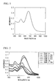
- a solution was prepared by adding 1.26 g of TDAB (tetradecylammonium bromide: compound II) to 3 ml of a CTAB (hexadecyltrimethylammonium bromide: surfactant (compound I)) solution having a concentration of 80 mM. 0.25 ml of a chlorauric acid solution having a concentration of 24mM, 0.065 ml of acetone, 0.045 ml of cyclohexane and 31.5 ⁇ l of a silver nitrate solution having a concentration of 10mM were added to that solution so as to obtain a reaction solution.
- TDAB tetradecylammonium bromide: compound II
- CTAB hexadecyltrimethylammonium bromide: surfactant (compound I)
- an ascorbic acid (AS) solution having a concentration of 40mM was added to this reaction solution so as to conduct a chemical reduction.
- AS ascorbic acid
- color of the reaction solution was changed from orange to clear.
- the clear solution was poured into a quartz cell having an optical path length of 1 cm, and was subjected to a light irradiation.
- an extra-high pressure mercury lamp 500 W was used and most of the visible light was cut off using an ultraviolet transmission filter (Sigma, UTVAF-33U).
- FIG. 1 shows an absorption spectrum of the reaction solution after the light irradiation for 15 minutes.
- TEM transmission electron microscope
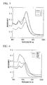
- Reaction solutions were prepared in the same manner as Embodiment 1, and the chemical reduction and the light irradiation were performed. However, instead of TDAB, another compound II was added at the same molar equivalent as that of TDAB in Embodiment 1.
- the chemical reduction using ascorbic acid and the light irradiation were conducted under the same conditions as those in Embodiment 1.
- the compounds II used in the present embodiment were the following five types ("n" indicates the number of - CH 2 - groups).
- Table 1 shows preparation conditions for the reaction solutions and light irradiation time until the change due to the light irradiation almost stopped.
- FIG. 2 shows the absorption spectra of the reaction solutions after the completion of the light irradiation.
- a chart using TDAB was shown as a comparison.
- Reaction solutions were prepared in the same manner similar as Embodiment 1, and the chemical reduction and the light irradiation were conducted. However, a different quantity of TDAB was added to one of the reaction solutions.
- Table 2 shows the preparation conditions for the reaction solutions and the light irradiation time until the change due to the light irradiation almost stopped.
- FIG. 3 shows the absorption spectra of the reaction solutions after the completion of light irradiation. As shown in FIG. 3, in each case, the absorption spectrum having two absorption peaks, which were distinctive to the gold nanorods, was obtained. Furthermore, according to the TEM observation, it could be also confirmed that the gold nanorods were generated in all the solutions. In comparison with Embodiment 1, with regard to the sample (No.
- Reaction solutions were prepared in the same manner similar as Embodiment 1, and the chemical reduction and the light irradiation were conducted. However, instead of the compound II, anionic surfactants were each added to the reaction solutions, and solutions containing CTAB and the anionic surfactant were prepared.
- the anionic surfactants in use were as follows. Table 3 shows the preparation conditions for the reaction solutions and the light irradiation time until the change due to the light irradiation stopped. Furthermore, FIG. 4 shows the absorption spectra of the reaction solutions after the completion of the light irradiation.
- Reaction solutions were prepared in the same manner similar as Embodiment 1, and the chemical reduction and the light irradiation were conducted. However, the compound II was not added to the reaction solutions, and solutions which did not contain any other surfactant besides CTAB were prepared. 31.5 ⁇ l, 100 ⁇ l, 150 ⁇ l and 200 ⁇ l of silver nitrate solutions having a concentration of 10mM were each added to one of these solutions, and the reaction solutions were prepared.
- the chemical reduction by ascorbic acid and the light irradiation were conducted under the same conditions as those in Embodiment 1. Ultraviolet rays were radiated for 30 minutes.
- FIG. 5 shows the absorption spectra of the reaction solutions after the light irradiation.
- Reaction solutions were prepared in the same manner similar as Embodiment 1, and the chemical reduction and the light irradiation were conducted.
- a CTAB solution having a concentration of 160mM was used.
- 200 ⁇ l of a silver nitrate solution having a concentration of 10 mM was added to the reaction solutions.
- a solution containing compound II (TDAB) (1.26 mg) and a solution not containing compound II were prepared, and the chemical reduction by ascorbic acid and the light irradiation for 15 minutes were conducted under the same conditions as those in Embodiment 1.
- FIG. 6 shows the absorption spectra of the reaction solutions after the light irradiation.
- the reaction solutions were prepared in the same manner as Embodiment 1, and the chemical reduction and the light irradiation were conducted. However, addition amount of silver was 200 ⁇ l.
- the solution was poured into a quartz cell having an optical path length of 1 mm, and ultraviolet rays under the same condition as that in Embodiment 1 were radiated from a side of the cell, and at the same time, a change of the absorption spectrum over time was measured. For the spectrum measurement, a multi-channel spectroscope was used.
- FIG. 7 shows the changes of the absorption spectra of the reaction solutions caused by a difference of the light irradiation time.
- Reaction solutions were prepared in the same manner similar as Embodiment 7, and the chemical reduction and the light irradiation were conducted.
- the light irradiation was conducted in both of a condition in which nitrogen was introduced to the reaction solution so as to bubble the solution and a condition in which no nitrogen was introduced, and a comparison was made between the absorption spectrum of the solution which was subjected to the nitrogen bubbling and that of the solution which was not subjected.
- measurements were conducted using a multi-channel spectroscope at the same time of the light irradiation.
- FIG. 8 shows a chart in which the absorbancies of the peaks of the longitudinal absorption were plotted relative to the light irradiation time.
- Reaction solutions were prepared by adding 0.25 ml of a chlorauric acid solution having a concentration of 24 mM, 0.065 ml of acetone, 0.045 ml of cyclohexane and 20.0 ml of a silver nitrate solution having a concentration of 10 mM to 3 ml of a CTAB solution having a concentration of 480mM.
- 0.2 ml of an ascorbic acid solution having a concentration of 40 mM was added to the reaction solution so as to conduct a chemical reduction, and then light was radiated into the solution. For the light irradiation, light of 10 mW/cm 2 was directly radiated into the reaction solution for 10 minutes.
- FIG. 9 shows one case in which after completion of the light irradiation into the reaction solution, the solution was left stationary for one hour, and then the solution was transferred to a storage container.
- FIG. 10 shows another case in which the solution was transferred immediately after the irradiation without leaving stationary.
- a solution was preparedby adding 1.26 mg of TDAB (compound II) to 3 ml of a CTAB solution having a concentration of 480 mM. 0.25 ml of a silver nitrate solution having a concentration of 24 mM, 0.065 ml of acetone and 0.045 ml of cyclohexane were added to this solution so as to obtain a reaction solution. After 0.2 ml of an ascorbic acid solution having a concentration of 40 mM was added to this reaction solution so aso to conduct a chemical reduction, and then light was radiated into this chemically reduced solution. For the light irradiation, light of 10 mW/cm 2 was directly radiated into the reaction solution for 10 minutes.
- FIG. 11 shows the absorption spectrum of the reaction solution after its being left stationary. As shown in the chart, the spectrum was obtained which had a peak (at or in a vicinity of 400 nm) resulting from spherical silver fine particles along with a peak (at or in a vicinity of 470 nm) resulting from rod-shaped particles (silver nanorods).
- a reaction solution was prepared by adding 0.25 ml of a chlorauric acid solution having a concentration of 24 mM, 0.065 ml of acetone, 0.045 ml of cyclohexane and 200 ⁇ l of a silver nitrate solution having a concentration of 10 mM to 3 ml of a CTAB (hexadecyltrimethylammonium bromide) solution having a concentration of 80 mM.
- CTAB hexadecyltrimethylammonium bromide
- 0.2 ml of an ascorbic acid (AS) solution having a concentration of 40mM to this reaction solution so as to conduct a chemical reduction.
- AS ascorbic acid
- the clear solution was poured into a quartz cell having an optical path length of 1 mm, and ultraviolet rays from an extra-high pressure mercury lamp (500 W), which were made to be monochromatic by a spectroscope (JOBIN YVON, HIOUV), were radiated for 15 minutes.
- Wavelengths of the ultraviolet rays were 280 nm (2.1 mW/cm 2 ), 289 nm (2.2 mW/cm 2 ), 297 nm (4.7 mW/cm 2 ), 303 nm (7.47 mW/cm 2 ), 315 nm (8.3 mW/cm 2 ) and 365 nm (11.0 mW/cm 2 ), respectively.
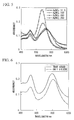
- FIG. 12 shows the absorption spectra after the ultraviolet irradiation which were standardized such that irradiation energy intensities be 6.1 mW.
- FIG. 13 shows a chart in which the absorption peaks resulted from the major axis of the gold nanorods were plotted relative to the wavelength of the radiated ultraviolet rays (action spectrum). As shown in the chart, it was confirmed that a generation efficiency of the gold nanorods increased dramatically from a vicinity of 310 nm.
- a reaction solution was prepared by adding 34 ml of a chlorauric acid solution having a concentration of 240mM, 6 ml of acetone, 1 ml of cyclohexane and 25 ml of a silver nitrate solution having a concentration of 10 mM to 400 ml of a CTAB (hexadecyl trimethyl ammonium bromide) solution having a concentration of 500 mM.
- 33 ml of an ascorbic acid solution having a concentration of 40 mM was added to this reaction solution so as to conduct a chemical reduction. Immediately after the ascorbic acid solution was added, color of the reaction solution was changed from orange to clear.
- the maximum absorption wavelength of the solution A was 880 nm and the absorbency was 1.6
- the maximum absorption wavelength of the solution B was 867 nm and the absorbency was 2.9. It was confirmed that in the case in which the non-radiated chlorauric acid solution and the reducing agent were mixed into the light-radiated solution A and the mixed solution was left stationary in a dark place, the gold nanorods could be manufactured catalytically while the solution was left stationary without radiating light.
- metal nanorods can be manufactured quickly and easily. Furthermore, a generation ratio of spherical metal nano-particles, which are by-products, is small; therefore, any fractionation and purification after the reaction are unnecessary. In addition, a configuration of the metal nanorods is easily controlled; thereby metal nanorods can be manufactured of which spectral characteristics in a wide wavelength region from the visible light to the near-infrared ray are controlled. Therefore, it is suitable for an industrial manufacturing.
Landscapes
- Chemical & Material Sciences (AREA)
- Engineering & Computer Science (AREA)
- Nanotechnology (AREA)
- Crystallography & Structural Chemistry (AREA)
- Materials Engineering (AREA)
- Organic Chemistry (AREA)
- Metallurgy (AREA)
- Chemical Kinetics & Catalysis (AREA)
- General Chemical & Material Sciences (AREA)
- Inorganic Chemistry (AREA)
- Condensed Matter Physics & Semiconductors (AREA)
- General Physics & Mathematics (AREA)
- Composite Materials (AREA)
- Physics & Mathematics (AREA)
- Manufacturing & Machinery (AREA)
- Manufacture Of Metal Powder And Suspensions Thereof (AREA)
Applications Claiming Priority (4)
| Application Number | Priority Date | Filing Date | Title |
|---|---|---|---|
| JP2003135062 | 2003-05-13 | ||
| JP2003314203 | 2003-09-05 | ||
| JP2004024006A JP4636454B2 (ja) | 2003-05-13 | 2004-01-30 | 金属ナノロッドの製造方法と用途 |
| PCT/JP2004/006804 WO2004101430A1 (fr) | 2003-05-13 | 2004-05-13 | Procede pour realiser une tige metallique nanometrique et son utilisation |
Publications (2)
| Publication Number | Publication Date |
|---|---|
| EP1623954A1 true EP1623954A1 (fr) | 2006-02-08 |
| EP1623954A4 EP1623954A4 (fr) | 2008-06-11 |
Family
ID=33458350
Family Applications (1)
| Application Number | Title | Priority Date | Filing Date |
|---|---|---|---|
| EP04732822A Withdrawn EP1623954A4 (fr) | 2003-05-13 | 2004-05-13 | Procede pour realiser une tige metallique nanometrique et son utilisation |
Country Status (7)
| Country | Link |
|---|---|
| US (2) | US7691176B2 (fr) |
| EP (1) | EP1623954A4 (fr) |
| JP (1) | JP4636454B2 (fr) |
| KR (1) | KR101162130B1 (fr) |
| CN (1) | CN1795141B (fr) |
| TW (1) | TW200510493A (fr) |
| WO (1) | WO2004101430A1 (fr) |
Cited By (8)
| Publication number | Priority date | Publication date | Assignee | Title |
|---|---|---|---|---|
| EP1769867A4 (fr) * | 2004-07-08 | 2008-06-04 | Mitsubishi Materials Corp | Procédé de fabrication de fine particule de métal, fine particule de métal produite ainsi, composition contenant ladite particule, matériau photo-absorbant, et application de celui-ci |
| EP1661648A4 (fr) * | 2003-09-05 | 2008-06-11 | Mitsubishi Materials Corp | Microparticule metallique, composition contenant ces microparticules et son procede de production de microparticules metalliques |
| WO2010129604A1 (fr) * | 2009-05-05 | 2010-11-11 | Cambrios Technologies Corporation | Films conducteurs fiables et durables comprenant des nanostructures métalliques |
| US20110185852A1 (en) * | 2006-06-21 | 2011-08-04 | Cambrios Technologies Corporation | Methods of controlling nanostructure formations and shapes |
| US8182574B2 (en) | 2003-09-05 | 2012-05-22 | Mitsubishi Materials Corporation | Metal fine particles, composition containing the same, and production method for producing metal fine particles |
| US8512438B2 (en) | 2009-08-25 | 2013-08-20 | Cambrios Technologies Corporation | Methods for controlling metal nanostructures morphology |
| US8541098B2 (en) | 2009-08-24 | 2013-09-24 | Cambrios Technology Corporation | Purification of metal nanostructures for improved haze in transparent conductors made from the same |
| US8865027B2 (en) | 2005-08-12 | 2014-10-21 | Cambrios Technologies Corporation | Nanowires-based transparent conductors |
Families Citing this family (67)
| Publication number | Priority date | Publication date | Assignee | Title |
|---|---|---|---|---|
| JP4512876B2 (ja) * | 2003-09-05 | 2010-07-28 | 三菱マテリアル株式会社 | 金属微粒子、金属微粒子を製造する方法及び金属微粒子を含有する組成物等 |
| JP4665499B2 (ja) * | 2004-12-10 | 2011-04-06 | 三菱マテリアル株式会社 | 金属微粒子とその製造方法とその含有組成物ならびにその用途 |
| US7745498B2 (en) * | 2005-04-13 | 2010-06-29 | Nanosys, Inc. | Nanowire dispersion compositions and uses thereof |
| JP5117679B2 (ja) * | 2005-04-27 | 2013-01-16 | 株式会社リコー | 多光子吸収材料を用いた色素材料、色素材料の製造方法、多光子吸収反応材料、多光子吸収反応材料の反応生成物、多光子吸収反応助剤、および色素溶液 |
| US8254227B2 (en) * | 2005-05-10 | 2012-08-28 | The Trustees Of The University Of Pennsylvania | Frequency-modulated coding and data recording and storage using plasmonic nanostructures |
| JP4852751B2 (ja) * | 2006-03-10 | 2012-01-11 | 国立大学法人九州大学 | 金属ナノワイヤーの製造方法 |
| KR100795480B1 (ko) * | 2006-04-14 | 2008-01-16 | 광주과학기술원 | 금 나노 입자 제조 방법 |
| KR101485304B1 (ko) | 2006-06-30 | 2015-01-23 | 미쓰비시 마테리알 가부시키가이샤 | 태양 전지의 전극 형성용 조성물 및 그 전극의 형성 방법, 그리고 그 형성 방법에 의해 얻어진 전극을 사용한 태양 전지 |
| JP5309521B2 (ja) | 2006-10-11 | 2013-10-09 | 三菱マテリアル株式会社 | 電極形成用組成物及びその製造方法並びに該組成物を用いた電極の形成方法 |
| US20080181851A1 (en) * | 2006-12-18 | 2008-07-31 | Samira Guccione | Photoacoustic contrast agents for molecular imaging |
| KR100873176B1 (ko) * | 2007-01-22 | 2008-12-10 | 한국생명공학연구원 | 할로겐 이온을 이용한 다양한 결정형의 금 나노입자의합성방법 |
| JP4854547B2 (ja) * | 2007-03-09 | 2012-01-18 | 独立行政法人科学技術振興機構 | 銀微粒子と核酸の複合体及びその製造方法 |
| JP5169389B2 (ja) | 2007-04-19 | 2013-03-27 | 三菱マテリアル株式会社 | 導電性反射膜の製造方法 |
| US20120164717A1 (en) * | 2007-07-18 | 2012-06-28 | Joseph Irudayaraj | Identity profiling of cell surface markers |
| CN101385978B (zh) * | 2007-09-12 | 2011-04-20 | 上海华谊丙烯酸有限公司 | 一种合成甲基丙烯醛的催化剂及其制备方法 |
| US8033715B2 (en) | 2007-11-08 | 2011-10-11 | Illinois Institute Of Technology | Nanoparticle based thermal history indicators |
| JP2009145643A (ja) * | 2007-12-14 | 2009-07-02 | Seiko Epson Corp | カラーフィルター用インク、カラーフィルター用インクセット、カラーフィルター、画像表示装置、および、電子機器 |
| JP2009221563A (ja) * | 2008-03-18 | 2009-10-01 | Ricoh Co Ltd | 金ナノロッドとその製造方法、金ナノロッドを用いた電磁波吸収体、色材、光記録材料および二光子反応材料 |
| JP2009270128A (ja) * | 2008-04-30 | 2009-11-19 | Osaka Prefecture Univ | 金ナノロッドの製造方法 |
| US7789935B2 (en) * | 2008-05-23 | 2010-09-07 | Xerox Corporation | Photochemical synthesis of metallic nanoparticles for ink applications |
| JP2009299162A (ja) * | 2008-06-16 | 2009-12-24 | Fujifilm Corp | 銀ナノワイヤー及びその製造方法、並びに水性分散物及び透明導電体 |
| US8268536B2 (en) | 2008-08-29 | 2012-09-18 | Korea University Research And Business Foundation | Electrode formation based on photo-induced reduction of metal ions in the presence of metal nanomaterials |
| KR101040323B1 (ko) * | 2008-08-29 | 2011-06-13 | 고려대학교 산학협력단 | 나노 구조체, 이를 포함하는 센서 및 그 제조방법 |
| US9574272B2 (en) * | 2008-09-02 | 2017-02-21 | Ramot At Tel-Aviv University Ltd | Metal nanowire thin-films |
| KR101042605B1 (ko) * | 2008-10-08 | 2011-06-20 | 연세대학교 산학협력단 | 금속 나노 구조체의 형성 방법 및 상기 방법에 의하여 형성된 금속 나노 구조체 |
| US20110195264A1 (en) * | 2008-10-14 | 2011-08-11 | Laird Technologies, Inc. | Acicular Metal Particles Having a High Aspect Ratio and Non-Catalytic Methods for Making the Same |
| KR101001631B1 (ko) * | 2009-06-15 | 2010-12-17 | 주식회사 아모그린텍 | 전기분해법을 이용한 은 나노 입자의 제조방법 및 그 장치 |
| WO2010147343A2 (fr) * | 2009-06-15 | 2010-12-23 | 주식회사 아모그린텍 | Procédé et appareil de production de particules d'argent de taille nanoscopique à l'aide d'une électrolyse |
| JP5690058B2 (ja) * | 2009-08-28 | 2015-03-25 | 国立大学法人九州大学 | 金ナノロッド構造体とその製造方法 |
| US20110048171A1 (en) * | 2009-08-28 | 2011-03-03 | Xerox Corporation | Continuous Reaction Process For Preparing Metallic Nanoparticles |
| CN101982774B (zh) * | 2010-09-30 | 2013-07-24 | 暨南大学 | 一种生物功能化的金纳米棒分子探针及其制备方法和应用 |
| US20120122363A1 (en) | 2010-11-16 | 2012-05-17 | Department Of The Air Force | Additives for Highly Repellent Polymeric Surfaces |
| CN102051680A (zh) * | 2011-01-21 | 2011-05-11 | 西安交通大学 | 一种小纵横比金纳米棒的快速制备方法 |
| CN103493149B (zh) * | 2011-04-28 | 2015-11-25 | 富士胶片株式会社 | 含有金属纳米线的分散液以及导电膜 |
| CN102284705A (zh) * | 2011-08-15 | 2011-12-21 | 东南大学 | 一种长径比可大范围调控的金纳米棒的制备方法 |
| CN102581299A (zh) * | 2012-02-21 | 2012-07-18 | 金淞电器(九江)有限公司 | 一种贵金属纳米粒子的光化学制备方法 |
| CN104508758B (zh) | 2012-03-01 | 2018-08-07 | 雷蒙特亚特特拉维夫大学有限公司 | 导电纳米线膜 |
| CN102590171A (zh) * | 2012-03-02 | 2012-07-18 | 南开大学 | 用于海洋油污染快速检测的系统 |
| US9006667B2 (en) | 2012-03-30 | 2015-04-14 | International Business Machines Corporation | Surface-modified fluorescent carbon nanotubes for product verification |
| US9333258B2 (en) * | 2012-05-08 | 2016-05-10 | The Regents Of The University Of California | Fine spatiotemporal control of fat removal using NIR light |
| US9040114B2 (en) * | 2012-08-29 | 2015-05-26 | Rohm And Haas Electronic Material Llc | Method of manufacturing silver miniwire films |
| JP6147860B2 (ja) | 2012-09-27 | 2017-06-14 | ロディア オペレーションズRhodia Operations | 銀ナノ構造を作製するための方法及び同方法に有用なコポリマー |
| US10543536B2 (en) | 2013-06-07 | 2020-01-28 | Lg Chem, Ltd. | Method for fabricating metal nanoparticles |
| KR101519970B1 (ko) * | 2013-07-23 | 2015-05-14 | 서강대학교산학협력단 | 액상과 액상 계면에서 덴드리머 형태의 금속 나노 구조체를 제조하는 방법 및 이에 따라 제조된 덴드리머 형태의 금속 나노 구조체 |
| JP6366988B2 (ja) * | 2014-04-25 | 2018-08-01 | 国立研究開発法人産業技術総合研究所 | 長さの揃った金又は銀ナノロッドの製造方法 |
| CN104001931B (zh) * | 2014-05-12 | 2016-01-06 | 燕山大学 | 利用棉铃虫杆状病毒核衣壳制备贵金属钯纳米棒的方法 |
| CN104132916A (zh) * | 2014-07-31 | 2014-11-05 | 湖南科技大学 | 一种检测葡萄糖和铜的含量的方法及其应用 |
| KR101700212B1 (ko) * | 2015-01-26 | 2017-01-26 | 덕산하이메탈(주) | 메탈 나노와이어의 합성방법 및 이를 통해 제조된 메탈 나노와이어 및 이를 포함하는 투광성 전극 및 유기발광소자 |
| KR101644185B1 (ko) * | 2015-01-26 | 2016-08-03 | 덕산하이메탈(주) | 코어-쉘 나노와이어의 합성방법 및 이를 통해 제조된 코어-쉘 나노와이어 및 이를 포함하는 투광성 전극 및 유기발광소자 |
| KR101700207B1 (ko) * | 2015-01-26 | 2017-01-26 | 덕산하이메탈(주) | 메탈 나노와이어의 합성방법 및 이를 통해 제조된 메탈 나노와이어 및 이를 포함하는 투광성 전극 및 유기발광소자 |
| CN104841950B (zh) * | 2015-05-22 | 2017-08-01 | 济南大学 | 一种狗骨状金纳米晶的制备方法 |
| CN106807952B (zh) * | 2015-12-01 | 2019-05-07 | 中国科学院大连化学物理研究所 | 一种合成Au25纳米球的方法及Au25纳米球 |
| EP3440904A4 (fr) | 2016-04-07 | 2019-12-11 | Technology Innovation Momentum Fund (Israel) Limited Partnership | Impression de films de nanofils |
| CN106130398B (zh) * | 2016-07-21 | 2019-10-01 | 王赞 | 一种光控热整流器以及提高热整流器热整流效率的方法 |
| CN106367510B (zh) * | 2016-09-20 | 2019-06-14 | 江南大学 | 一种用于胞内癌症标志物双重检测的卫星状纳米组装体的制备方法及应用 |
| KR102424876B1 (ko) * | 2017-04-28 | 2022-07-22 | 엘지디스플레이 주식회사 | 키랄성 금속 나노구조체를 이용한 암호화 방법 |
| CN112974829A (zh) * | 2020-12-29 | 2021-06-18 | 杭州电子科技大学 | 一种在双表面活性剂下对苯二酚还原制备金纳米棒材料的方法 |
| CN113681021A (zh) * | 2021-08-20 | 2021-11-23 | 杭州电子科技大学 | 一种基于胶束沉积作用的金纳米棒提纯方法 |
| CN114293183B (zh) * | 2021-12-16 | 2023-07-18 | 南方科技大学 | 基于上转换材料的近红外光诱导金属纳米结构生长的方法 |
| CN114890526B (zh) * | 2022-05-19 | 2023-10-03 | 北京科技大学 | 一种含氟氯污酸中分步脱除氟氯的方法 |
| CN115128059A (zh) * | 2022-06-22 | 2022-09-30 | 宁波大学 | 基于黑磷@金-银纳米复合材料的sers芯片及其制备方法 |
| CN115650998A (zh) * | 2022-10-24 | 2023-01-31 | 江苏大学 | 一种纳米荧光探针及其制备方法与应用 |
| CN116967459A (zh) * | 2023-04-11 | 2023-10-31 | 南宁师范大学 | 一种以甲氧基对苯二酚为还原剂的金纳米棒制备方法 |
| CN116571736B (zh) * | 2023-05-22 | 2026-03-27 | 无锡学院 | 一种调控金纳米棒长度的方法 |
| CN117020197B (zh) * | 2023-06-27 | 2026-03-06 | 山东大学 | 一种混合溶剂诱导的高荧光银纳米团簇及其制备方法与在led中的应用 |
| CN120961938A (zh) * | 2025-08-27 | 2025-11-18 | 苏州大学 | 一种棒状铜粉的制备方法 |
| CN121289497B (zh) * | 2025-12-11 | 2026-03-17 | 常德市国银新材料有限公司 | 用于低温烧结银浆的高分散纳米银粉生产方法 |
Family Cites Families (8)
| Publication number | Priority date | Publication date | Assignee | Title |
|---|---|---|---|---|
| JPS621826A (ja) * | 1985-06-26 | 1987-01-07 | Mitsubishi Electric Corp | 金属の析出方法 |
| JPH06102146B2 (ja) * | 1985-09-12 | 1994-12-14 | 三菱電機株式会社 | 光化学反応による金属コロイドの生成方法 |
| JPS6263603A (ja) * | 1985-09-12 | 1987-03-20 | Mitsubishi Electric Corp | 光化学反応による金属コロイドの生成方法 |
| CN1060702C (zh) * | 1995-01-16 | 2001-01-17 | 中国科学技术大学 | 纳米金属微粉的电离辐射化学氧化还原制备方法 |
| JP4178582B2 (ja) | 1998-04-08 | 2008-11-12 | 満 明石 | 金属コロイド溶液およびその製造方法 |
| JP3000000B1 (ja) | 1998-09-01 | 2000-01-17 | 科学技術振興事業団 | 金属・有機ポリマー複合構造体とその製造方法 |
| EP1215205B1 (fr) * | 2000-12-08 | 2007-11-21 | Sony Deutschland GmbH | Linker molécules multifonctionnelles accordées pour le transport électronique de charge par les structures composites organique-inorganiques et l'utilisation de ces structures |
| CN1196554C (zh) * | 2002-11-01 | 2005-04-13 | 中国科学院理化技术研究所 | 一维纳米银材料的制备方法 |
-
2004
- 2004-01-30 JP JP2004024006A patent/JP4636454B2/ja not_active Expired - Fee Related
- 2004-05-13 EP EP04732822A patent/EP1623954A4/fr not_active Withdrawn
- 2004-05-13 KR KR1020057021286A patent/KR101162130B1/ko not_active Expired - Fee Related
- 2004-05-13 TW TW093113516A patent/TW200510493A/zh not_active IP Right Cessation
- 2004-05-13 WO PCT/JP2004/006804 patent/WO2004101430A1/fr not_active Ceased
- 2004-05-13 US US10/556,498 patent/US7691176B2/en not_active Expired - Fee Related
- 2004-05-13 CN CN2004800125393A patent/CN1795141B/zh not_active Expired - Fee Related
-
2010
- 2010-02-11 US US12/704,364 patent/US7976609B2/en not_active Expired - Fee Related
Cited By (20)
| Publication number | Priority date | Publication date | Assignee | Title |
|---|---|---|---|---|
| US8182574B2 (en) | 2003-09-05 | 2012-05-22 | Mitsubishi Materials Corporation | Metal fine particles, composition containing the same, and production method for producing metal fine particles |
| EP1661648A4 (fr) * | 2003-09-05 | 2008-06-11 | Mitsubishi Materials Corp | Microparticule metallique, composition contenant ces microparticules et son procede de production de microparticules metalliques |
| EP2165791A3 (fr) * | 2003-09-05 | 2010-04-14 | Mitsubishi Materials Corporation | Microparticule métallique, composition la contenant et procédé de production de microparticule métallique |
| EP2189232A1 (fr) * | 2003-09-05 | 2010-05-26 | Mitsubishi Materials Corporation | Microparticule métallique, composition la contenant et procédé de production de microparticule métallique |
| US7527668B2 (en) | 2004-07-08 | 2009-05-05 | Mitsubishi Materials Corporation | Method for manufacturing metal fine particles, metal fine particles manufactured thereby, and composition, light absorbing material and applied products containing the same |
| EP1769867A4 (fr) * | 2004-07-08 | 2008-06-04 | Mitsubishi Materials Corp | Procédé de fabrication de fine particule de métal, fine particule de métal produite ainsi, composition contenant ladite particule, matériau photo-absorbant, et application de celui-ci |
| US8865027B2 (en) | 2005-08-12 | 2014-10-21 | Cambrios Technologies Corporation | Nanowires-based transparent conductors |
| US9899123B2 (en) | 2005-08-12 | 2018-02-20 | Jonathan S. Alden | Nanowires-based transparent conductors |
| US20110185852A1 (en) * | 2006-06-21 | 2011-08-04 | Cambrios Technologies Corporation | Methods of controlling nanostructure formations and shapes |
| US8454721B2 (en) | 2006-06-21 | 2013-06-04 | Cambrios Technologies Corporation | Methods of controlling nanostructure formations and shapes |
| US10195670B2 (en) * | 2006-06-21 | 2019-02-05 | Cambrios Film Solutions Corporation | Methods of controlling nanostructure formations and shapes |
| US9440291B2 (en) | 2006-06-21 | 2016-09-13 | Champ Great Int'l Corporation | Methods of controlling nanostructure formations and shapes |
| US10875098B2 (en) * | 2006-06-21 | 2020-12-29 | Cambrios Film Solutions Corporation | Methods of controlling nanostructure formations and shapes |
| US8709125B2 (en) * | 2006-06-21 | 2014-04-29 | Cambrios Technologies Corporation | Methods of controlling nanostructure formations and shapes |
| CN102460600B (zh) * | 2009-05-05 | 2016-06-01 | 凯博瑞奥斯技术公司 | 包含金属纳米结构的可靠且持久的导电膜 |
| CN103551566A (zh) * | 2009-05-05 | 2014-02-05 | 凯博瑞奥斯技术公司 | 包含金属纳米结构的可靠且持久的导电膜 |
| CN102460600A (zh) * | 2009-05-05 | 2012-05-16 | 凯博瑞奥斯技术公司 | 包含金属纳米结构的可靠且持久的导电膜 |
| WO2010129604A1 (fr) * | 2009-05-05 | 2010-11-11 | Cambrios Technologies Corporation | Films conducteurs fiables et durables comprenant des nanostructures métalliques |
| US8541098B2 (en) | 2009-08-24 | 2013-09-24 | Cambrios Technology Corporation | Purification of metal nanostructures for improved haze in transparent conductors made from the same |
| US8512438B2 (en) | 2009-08-25 | 2013-08-20 | Cambrios Technologies Corporation | Methods for controlling metal nanostructures morphology |
Also Published As
| Publication number | Publication date |
|---|---|
| JP4636454B2 (ja) | 2011-02-23 |
| US20100143184A1 (en) | 2010-06-10 |
| TW200510493A (en) | 2005-03-16 |
| US7976609B2 (en) | 2011-07-12 |
| EP1623954A4 (fr) | 2008-06-11 |
| KR101162130B1 (ko) | 2012-07-03 |
| TWI339674B (fr) | 2011-04-01 |
| US7691176B2 (en) | 2010-04-06 |
| CN1795141B (zh) | 2012-02-01 |
| CN1795141A (zh) | 2006-06-28 |
| JP2005097718A (ja) | 2005-04-14 |
| KR20060017776A (ko) | 2006-02-27 |
| WO2004101430A1 (fr) | 2004-11-25 |
| US20060196309A1 (en) | 2006-09-07 |
Similar Documents
| Publication | Publication Date | Title |
|---|---|---|
| US7976609B2 (en) | Method for manufacturing metal nanorods and use thereof | |
| Muhammed et al. | Growth of in situ functionalized luminescent silver nanoclusters by direct reduction and size focusing | |
| Osminkina et al. | Photoluminescent biocompatible silicon nanoparticles for cancer theranostic applications | |
| US11193034B2 (en) | Hybrid nanoparticles as photoinitiators | |
| Zhu et al. | Additive controlled synthesis of gold nanorods (GNRs) for two-photon luminescence imaging of cancer cells | |
| EP2165791B1 (fr) | Procédé de production de nanobâtonnets d'or | |
| Mishra et al. | Gold-doped silver nanoclusters with enhanced photophysical properties | |
| TWI458833B (zh) | 奈米金屬分散液及其製法 | |
| US20060266157A1 (en) | Metal fine particles, composition containing the same, and production method for producing metal fine particles | |
| Wang et al. | Synthesis of highly stable fluorescent Ag nanocluster@ polymer nanoparticles in aqueous solution | |
| EP4299524A1 (fr) | Nanoparticules semi-conductrices comprenant un composé à base d'agaus | |
| Xu et al. | Seed-mediated growth approach for rapid synthesis of high-performance red-emitting CdTe quantum dots in aqueous phase and their application in detection of highly reactive oxygen species | |
| CN101284313B (zh) | 金属微粒的制造方法及含有该微粒的组合物 | |
| Mallick et al. | Polymer-stabilized colloidal gold: a convenient method for the synthesis of nanoparticles by a UV-irradiation approach | |
| US20110111233A1 (en) | Inorganic nanoparticle labeling agent | |
| CA3241285A1 (en) | Peptide-protected gold nanocluster and use in photodynamic therapy | |
| Liu et al. | Structure, luminescence, and bioimaging of bimetallic CuAu nanoclusters | |
| KR102652626B1 (ko) | 생물 직교 촉매로서 플라즈모닉 나노구조체를 포함하는 약학적 조성물 및 이를 이용하는 증식성 질환의 예방 또는 치료 방법 | |
| TWI542710B (zh) | 光致螢光金奈米粒子及其製造方法 | |
| CN116554859A (zh) | 一种近红外光激发超微纳米团簇及其制备方法和应用 | |
| KR101076328B1 (ko) | 양성자 빔 조사를 통한 은 나노입자 합성 방법 | |
| RU2782138C1 (ru) | Способ получения квантовых точек сульфида серебра в органической оболочке | |
| JP2021509443A (ja) | ct−DNA及びBSAにおける自己組織化した銀ナノ粒子の光化学合成及び特性評価 | |
| Jorge et al. | Synthesis and Characterization of Novel Silylated Sm3+ and Eu3+ Complexes Incorporated into Mesoporous and Dense Silica Nanoparticles | |
| Cheng et al. | Ultrasensitive SERS Platform for Cisplatin Detection using Self-Assembled Gold Nanooctahedra-Silver Nanocube Core-Shell Nanoparticles |
Legal Events
| Date | Code | Title | Description |
|---|---|---|---|
| PUAI | Public reference made under article 153(3) epc to a published international application that has entered the european phase |
Free format text: ORIGINAL CODE: 0009012 |
|
| 17P | Request for examination filed |
Effective date: 20051110 |
|
| AK | Designated contracting states |
Kind code of ref document: A1 Designated state(s): DE FR GB |
|
| DAX | Request for extension of the european patent (deleted) | ||
| RBV | Designated contracting states (corrected) |
Designated state(s): DE FR GB |
|
| A4 | Supplementary search report drawn up and despatched |
Effective date: 20080515 |
|
| 17Q | First examination report despatched |
Effective date: 20081119 |
|
| GRAP | Despatch of communication of intention to grant a patent |
Free format text: ORIGINAL CODE: EPIDOSNIGR1 |
|
| RIC1 | Information provided on ipc code assigned before grant |
Ipc: B22F 9/24 20060101ALI20180627BHEP Ipc: B82Y 30/00 20110101ALI20180627BHEP Ipc: C30B 7/14 20060101ALI20180627BHEP Ipc: B82B 3/00 20060101AFI20180627BHEP Ipc: C30B 29/60 20060101ALI20180627BHEP Ipc: B22F 1/00 20060101ALN20180627BHEP Ipc: C30B 7/00 20060101ALI20180627BHEP |
|
| RIC1 | Information provided on ipc code assigned before grant |
Ipc: B22F 1/00 20060101ALN20180702BHEP Ipc: C30B 29/60 20060101ALI20180702BHEP Ipc: C30B 7/14 20060101ALI20180702BHEP Ipc: C30B 7/00 20060101ALI20180702BHEP Ipc: B22F 9/24 20060101ALI20180702BHEP Ipc: B82B 3/00 20060101AFI20180702BHEP Ipc: B82Y 30/00 20110101ALI20180702BHEP |
|
| INTG | Intention to grant announced |
Effective date: 20180725 |
|
| STAA | Information on the status of an ep patent application or granted ep patent |
Free format text: STATUS: THE APPLICATION IS DEEMED TO BE WITHDRAWN |
|
| 18D | Application deemed to be withdrawn |
Effective date: 20181205 |