EP1625946B1 - Appareil de finition pour feuilles et méthode pour le contrôler - Google Patents
Appareil de finition pour feuilles et méthode pour le contrôler Download PDFInfo
- Publication number
- EP1625946B1 EP1625946B1 EP05252570A EP05252570A EP1625946B1 EP 1625946 B1 EP1625946 B1 EP 1625946B1 EP 05252570 A EP05252570 A EP 05252570A EP 05252570 A EP05252570 A EP 05252570A EP 1625946 B1 EP1625946 B1 EP 1625946B1
- Authority
- EP
- European Patent Office
- Prior art keywords
- sheet
- sheet bundle
- stacked
- bundle
- bound
- Prior art date
- Legal status (The legal status is an assumption and is not a legal conclusion. Google has not performed a legal analysis and makes no representation as to the accuracy of the status listed.)
- Expired - Lifetime
Links
Images


Classifications
-
- B—PERFORMING OPERATIONS; TRANSPORTING
- B65—CONVEYING; PACKING; STORING; HANDLING THIN OR FILAMENTARY MATERIAL
- B65H—HANDLING THIN OR FILAMENTARY MATERIAL, e.g. SHEETS, WEBS, CABLES
- B65H31/00—Pile receivers
-
- B—PERFORMING OPERATIONS; TRANSPORTING
- B42—BOOKBINDING; ALBUMS; FILES; SPECIAL PRINTED MATTER
- B42C—BOOKBINDING
- B42C1/00—Collating or gathering sheets combined with processes for permanently attaching together sheets or signatures or for interposing inserts
- B42C1/12—Machines for both collating or gathering and permanently attaching together the sheets or signatures
-
- B—PERFORMING OPERATIONS; TRANSPORTING
- B65—CONVEYING; PACKING; STORING; HANDLING THIN OR FILAMENTARY MATERIAL
- B65H—HANDLING THIN OR FILAMENTARY MATERIAL, e.g. SHEETS, WEBS, CABLES
- B65H31/00—Pile receivers
- B65H31/04—Pile receivers with movable end support arranged to recede as pile accumulates
- B65H31/06—Pile receivers with movable end support arranged to recede as pile accumulates the articles being piled on edge
-
- B—PERFORMING OPERATIONS; TRANSPORTING
- B65—CONVEYING; PACKING; STORING; HANDLING THIN OR FILAMENTARY MATERIAL
- B65H—HANDLING THIN OR FILAMENTARY MATERIAL, e.g. SHEETS, WEBS, CABLES
- B65H31/00—Pile receivers
- B65H31/30—Arrangements for removing completed piles
- B65H31/3027—Arrangements for removing completed piles by the nip between moving belts or rollers
-
- B—PERFORMING OPERATIONS; TRANSPORTING
- B65—CONVEYING; PACKING; STORING; HANDLING THIN OR FILAMENTARY MATERIAL
- B65H—HANDLING THIN OR FILAMENTARY MATERIAL, e.g. SHEETS, WEBS, CABLES
- B65H31/00—Pile receivers
- B65H31/30—Arrangements for removing completed piles
- B65H31/3081—Arrangements for removing completed piles by acting on edge of the pile for moving it along a surface, e.g. by pushing
-
- B—PERFORMING OPERATIONS; TRANSPORTING
- B65—CONVEYING; PACKING; STORING; HANDLING THIN OR FILAMENTARY MATERIAL
- B65H—HANDLING THIN OR FILAMENTARY MATERIAL, e.g. SHEETS, WEBS, CABLES
- B65H2301/00—Handling processes for sheets or webs
- B65H2301/10—Selective handling processes
- B65H2301/16—Selective handling processes of discharge in bins, stacking, collating or gathering
- B65H2301/163—Bound or non bound, e.g. stapled or non stapled stacking mode
-
- B—PERFORMING OPERATIONS; TRANSPORTING
- B65—CONVEYING; PACKING; STORING; HANDLING THIN OR FILAMENTARY MATERIAL
- B65H—HANDLING THIN OR FILAMENTARY MATERIAL, e.g. SHEETS, WEBS, CABLES
- B65H2301/00—Handling processes for sheets or webs
- B65H2301/40—Type of handling process
- B65H2301/42—Piling, depiling, handling piles
- B65H2301/422—Handling piles, sets or stacks of articles
- B65H2301/4226—Delivering, advancing piles
- B65H2301/42262—Delivering, advancing piles by acting on surface of outermost articles of the pile, e.g. in nip between pair of belts or rollers
-
- B—PERFORMING OPERATIONS; TRANSPORTING
- B65—CONVEYING; PACKING; STORING; HANDLING THIN OR FILAMENTARY MATERIAL
- B65H—HANDLING THIN OR FILAMENTARY MATERIAL, e.g. SHEETS, WEBS, CABLES
- B65H2301/00—Handling processes for sheets or webs
- B65H2301/40—Type of handling process
- B65H2301/42—Piling, depiling, handling piles
- B65H2301/422—Handling piles, sets or stacks of articles
- B65H2301/4226—Delivering, advancing piles
- B65H2301/42266—Delivering, advancing piles by acting on edge of the pile for moving it along a surface, e.g. pushing
-
- B—PERFORMING OPERATIONS; TRANSPORTING
- B65—CONVEYING; PACKING; STORING; HANDLING THIN OR FILAMENTARY MATERIAL
- B65H—HANDLING THIN OR FILAMENTARY MATERIAL, e.g. SHEETS, WEBS, CABLES
- B65H2801/00—Application field
- B65H2801/24—Post -processing devices
- B65H2801/27—Devices located downstream of office-type machines
Definitions
- the present invention relates to a sheet finisher and control method thereof, wherein the sheet finisher that receives a sheet with an image formed thereon by an image forming apparatus such as a copier and printer, applies a process of binding to the sheet by means of a binding device, and ejects the sheet to an ejection tray.
- an image forming apparatus such as a copier and printer
- a sheet finisher In a sheet finisher, the sheets with images formed thereon by an image forming apparatus are stacked by a predetermined stacking means and are formed into a bundle of sheets, which are then provided with a process of binding to create a booklet or a document.
- This sheet finisher is widely used as a peripheral apparatus connected with an image forming apparatus.
- the disclosed sheet finishers include the apparatus provided with a punching means for punching the sheets having been stacked by the stacking means, similarly to the process of binding or stapling the sheets.
- Patent Document 3 Patent Document 3
- a frequently used means for binding a sheet bundle includes a means that uses an apparatus called a stapler for binding the ends of the sheet bundle with a wire staple, and a means for binding by heating the binding tape coated with hot melt type paste and bringing it in contact with the side edge of the sheet bundle (e.g. Patent Document 1).
- the work performed by a user using the image forming apparatus connected with a sheet finisher having the aforementioned binding means further contains the work of applying a process of binding, and the work of simply ejecting the sheets with images formed thereon, to an ejection tray and stacking them, without applying the process of binding.
- the sheet finisher is provided with a sheet conveyance path for leading the sheets coming out of an image forming apparatus to a binding means and then leading the bound sheet bundle to an ejection tray, and a sheet conveyance path for leading the aforementioned sheets directly to the ejection tray, without feeding the sheets to the binding means.
- Two sheet conveyance paths arranged in such an apparatus causes increased costs and discourages downsizing of the apparatus. For this reason, a proposal has been made to integrate two sheet conveyance paths into device (e.g. Patent Document 2)
- Integrating the sheet conveyance paths into one necessarily results in the arrangement of only the sheet conveyance path for leading the sheet to the binding means.
- a means of switching the sheet conveyance path is arranged in the vicinity of the binding means. The sheet conveyance path for applying the process of binding and the sheet conveyance path not intended to apply the process of binding are switched in response to the requirements.
- the bound sheet bundle is ejected to the ejection tray every time binding has completed. After the sheet conveyance path has been switched, the apparatus handles the next process where binding is not performed. Such an operation cycle is repeated. The switching operation frequently repeated drastically reduces the processing capability of the sheet finisher, with the result that the image forming apparatus is placed in the operation wait status more frequently.
- Patent Document 1 denotes Official Gazette of Japanese Patent Application Tokkaihei 7-89259
- Patent Document 2 denotes Official Gazette of Japanese Patent Application Tokkaihei 9-240909
- Patent Document 3 denotes Official Gazette of Japanese Patent Application Tokkaihei 5-105308
- the present invention is intended to avoid reduction of the processing capacity of a sheet finisher as described above.
- the object of the present invention is to provide a sheet finisher wherein a sheet bundle not having been subjected to the process of binding is stacked on a sheet bundle having been subjected to the process of binding, and these sheet bundles are integrated into one bundle, which is ejected to the ejection tray, thereby minimizing the frequency of switching a sheet conveyance path.
- the aforementioned object can be achieved by implementing any one of the Items (1) through (4) described below.
- a sheet bundle having been subjected to the process of binding is made to wait on the sheet stacking means, and the sheet, not having been subjected to the process of binding, coming out of the image forming apparatus is placed on the sheet bundle in the wait state.
- Control is provided in such a way that the sheet bundle and sheets are integrated as one bundle and are ejected to this ejection tray by the ejection means.
- the Item (1) reduces the frequency of switching the sheet conveyance path of the sheet finisher and minimizes reduction in the processing performances of a system composed of the image forming apparatus and sheet finisher. Further, the sheet bundle having been subjected to the process of binding and the sheet bundle not having been subjected to the process of binding constitutes one part. This part constituted in this manner is handled as one body and is ejected to the ejection tray. Such functions of the sheet finisher are provided by the Item (1).
- the sheet bundle stacked on the sheet stacking means is ejected from the sheet stacking means.
- the Item (3) avoids stacking of sheet bundles in excess of the maximum stacking capability of the sheet stacking means. This arrangement avoids incorrect binding or ejection of the sheet bundles.
- the Item (4) reduces the frequency of switching the sheet conveyance path of the sheet finisher and minimizes reduction in the processing performances of a system composed of the image forming apparatus and sheet finisher. Further, the sheet bundle having been subjected to the process of binding and the sheet bundle not having been subjected to the process of binding constitutes one part. This part constituted in this manner is handled as one body and is ejected to the ejection tray. A control method of a sheet finisher having such functions is provided by the Item (4).
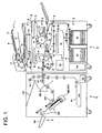
- Fig. 1 is a conceptual diagram representing an image forming system wherein the sheet finisher and image recording apparatus are connected with each other.
- the image forming apparatus A is a digital copying machine for forming an image using a known electrophotographic technology.
- An automatic document feeder 1 is installed on the top of the image forming apparatus A, which is connected with a sheet finisher B.
- the image forming apparatus A comprises an automatic document feeder 1, a reading means 2, a writing means 3, an image forming means 4, a fixing means 5, a reversing or ejecting means 6, a re-feeding means 7, a sheet conveyance means 8, a sheet feeding means 9, a control means C1 and an operation and display means E.
- the automatic document feeder 1 ensures that the documents D placed on the document platen 10 are fed one by one to a document conveyance path 11, and so that the documents are ejected to a document ejection platen 12.
- the image surface of the document D which is being carried is read by the reading means 2 at the document reading position 13.
- the document D whose first side has been read is reversed by a reversing means 14, is sent again to the document conveyance path 11 whose second side is read, is then ejected to the document ejection platen 12.
- the reading means 2 comprises a light source 21, a first mirror unit 22, a second mirror unit 23, image forming lens 24, and a CCD 25. Scanning the image of the documents D passing through the document reading position 13, the reading means 2 allows the image to be formed on the CCD 25, and converts the document image information as optical information into electrical information. The document image information converted in this manner is subjected to A/D conversion, shading correction and compression, and is stored in the memory M1 of the control means C1.
- the writing means 3 is a scanning optical system composed of a laser light source, cylindrical lens, an F ⁇ lens, a mirror and a polygon mirror. Using the laser beam changing in response to the image information read from the aforementioned memory M, the writing means 3 scans the surface of the photoconductor 41 of the image forming means 4, and forms a latent image on the surface of the photoconductor 41.
- the image forming means 4 uses a development means 42 to develop a latent image formed on the surface of a photoconductor 41 so that the latent image is turned into a toner image.
- a transfer means 43 the toner image is transferred on the sheet P fed out by a registration roller 81.
- the residual toner is removed by a cleaning means 44 from the surface of the photoconductor with the toner image having been transferred. It is electrically charged by a charging means 45 and is used in the next process of forming a latent image.
- the fixing means 5 applies heat and pressure to the sheet P carrying a toner image, by means of a heat roller 51 and a pressure roller 52 arranged opposite thereto. Then the toner image is fixed onto the sheet P.
- the sheet P with an image having been fixed thereon is sent to the sheet finisher B by an ejection roller 55.
- the sheet P When the sheet P is reversed and ejected, the sheet P is led downward by an ejection guide 57 and the trailing edge of the sheet P is pinched between reversing rollers 61 of the reversing means. Then the sheet P is reversed and is fed out to the ejection roller 55.
- the sheet P When an image is formed on both sides of the sheet P, the sheet P is fed to the re-feeding means 7 by the ejection guide 57 and a plurality of rollers. The sheet P is reversed by the reversing roller 71 and is fed again to the sheet conveyance means 8.
- the sheet conveyance means 8 conveys the sheet P fed out of the sheet feeding means 9 along the conveyance path containing a plurality of rollers and guide member. After the leading edge of the sheet P has contacted the registration roller 81, the sheet conveyance means 8 feeds out to the photoconductor 41 for receiving the toner image.
- the sheet feeding means 9 comprises a first sheet feed means 91 containing a small-capacity tray, a second sheet feed means 92 containing a large-capacity tray, and a third sheet feed means 93. These sheet feed means are provided with feeding rollers 916, 926 and 936 for feeding the sheets P mounted on each tray one by one to the sheet conveyance means 8.
- the second sheet feed means 92 and third sheet feed means 93 are provided with a top surface detecting means for detecting the top surface position of the stacked sheets. According to the top surface detection signal from this top surface detecting means, the control means C1 vertically moves the bottom of the tray carrying the sheet P.
- the operation and display means E has both the display and input functions, using the touch panel installed on the top surface of the image forming apparatus A. It is employed by the user to input an operation command to the control means C1, including the cases of setting the number of the copies to be taken, or setting whether or not the outputted copies are subjected to the process of finishing.
- the sheet finisher B comprises a distribution guide 101, a sheet conveyance means 100 containing a plurality of rollers and guide members, an intermediate stacker 200 as a sheet stacking means for stacking sheets P and forming a sheet bundle, a binding means 500 for binding the aforementioned sheet bundle (a punching means 600 for punching the sheet bundle may be additionally provided), an ejection means 300 for ejecting the sheet bundle on the intermediate stacker, an ejection tray 103 for stacking the ejected sheet bundles sequentially, an ejection platen 102 for stacking a small quantity of paper, a sheet stacking means 900 and a control means C2.
- the sheet P When the user has operated the operation and display means E to select the mode where finishing is not performed, and to select a small quantity of sheets, then the sheet P, with an image formed by the image forming apparatus A, having been fed to the sheet finisher B, is led upward by the first sheet member 101. The sheet P is then ejected to the ejection platen 102 by the sheet conveyance means 100.
- the sheet P is led downward to the intermediate stacker 200 by the first sheet member 101.
- the sheet finisher B of the present invention is also capable of placing the cover or the sheet P1 to be inserted between pages on a sheet accommodation means 900, and feeding out the accommodated sheet P1 to the intermediate stacker 200 so that it will be located within the page position of the sheet P fed from the image forming apparatus A.
- Fig. 2 is a conceptual diagram representing the vicinity of an intermediate stacker 200.
- the sheet P fed from the right (a) of the drawing is conveyed to the intermediate stacker 200 by a plurality of conveyance rollers 110, 111, 120 and 121 constituting the sheet conveyance means 100 and a plurality of guide members 150, 151, 160 and 160.
- This intermediate stacker 200 is a plate-formed member held to have an angle of about 45 degrees relative to the horizontal plane.
- the first ejection roller 330 and the second ejection roller 340 move to the position indicated by the dotted line.
- the sheet P is fed and ejected to the ejection tray 103.
- the ejection means 300 comprises a first ejection roller 330 whose position is controlled by the control means C2, a second ejection roller 340, a drive pulley 210, a driven pulley 211, an ejection belt 212, an ejection claw 213, a plurality of rollers and guide members.
- the first ejection roller 330 is kept at the position of the solid line in the drawing.
- the sheet P whose trailing edge has separated from the conveyance rollers 120 and 121 on the intermediate stacker 200 slips down along the intermediate stacker surface.
- the trailing edge collides with the contact member 201 and the movement is stopped.
- the next sheets P having been fed out slip down and sequentially stacked on the sheet P having been fed previously, with the trailing edges kept in alignment.
- the position of the sides of the sheet is regulated by the side guides (not illustrated) arranged on the side of the intermediate stacker 200.
- the edges of the sheets P are kept in alignment by the contact member 201 and side guides, and these sheets P are stacked on the intermediate stacker 200.
- the stacking amount detecting means S detects the stacking amount detecting means S.
- the outputting of the sheets P from the image forming apparatus A is suspended and the sheets P stacked on the intermediate stacker 200 are ejected to the ejection tray 103.
- the binding means of the present invention is a commonly known means called the stapler wherein the sheet bundle is bound by a wire staple.
- An adequate means other than the stapler can be used as the binding means 500.
- a notch is formed on part of the sheet stacking surface of the intermediate stacker 200, the drive pulley 210 and driven pulley 211 constituting the ejection means 300, and a plurality of ejection belts 212 turned by these pulleys are rotatably arranged.
- Part of the ejection belt 212 is provided with the ejection claw 213. Its tip generates an elliptical locus, as indicated by a one-dot chain line in the drawing.
- the end of the sheet bundle, with one of the ends bound by the binding means 500, is held by the ejection claw 213 moved by the rotation of the ejection belt 212. While slipping down sheet stacking surface of the intermediate stacker 200 is pushed obliquely upward, the sheet bundle is pinched between the rotating second ejection rollers and is ejected to the ejection tray 103.
- the ejection tray 103 is a well known tray for sequentially stacking the sheets P ejected by the second ejection rollers 340 and 341 or the sheet bundles having been subjected to the process of binding. It is vertically movable, and is controlled in such a way that the top surfaces of the stacked sheets P or sheet bundles are located always at a constant position.
- the sheet bundle having been subjected to the process of binding is ejected first. Then the positions of the first ejection roller 330 and second ejection roller 340 are shifted to the sheet-P conveyance position (indicated by the dotted line in the drawing). During this process of ejection and the process of switching the sheet conveyance path by the roller position shift, outputting of the sheets P from the image forming apparatus A is disabled. Thus, the image forming apparatus A is placed in the wait mode. Consequently, if switching of the process is performed frequently, the throughput of the system composed of the image forming apparatus A and sheet finisher B will be reduced. This creates a problem.
- a procedure of repeating alternately the process with binding and the process without binding is exemplified by a function called a subset binding function.
- the subset binding function one set of sheets is divided into plural subsets including at least one sheet and at least one sheet bundle which is subjected to binding, and is outputted.
- An example of the output is shown in Fig. 7 .
- one set of sheets is composed of one sheet not to be bound and three sheets to be bound, and three sets of sheets are outputted.
- This example includes a total of three steps of switching from a non-binding mode to a binding mode for locations between 1 st and 2 nd sheets, between 5 th and 6 th sheets, and between 9 th and 10 th sheets; and a total of two steps of switching from the binding mode to the non-binding mode for locations between 4 th and 5 th sheets, and between 8 th and 9 th sheets.
- the operation throughput is much reduced by a great number of the switching operations, as described above.
- a procedure of repeating alternately the process with punching and the process without punching is exemplified by a function called a subset punching.
- the subset punching function one set of sheets is divided into plural subsets including at least one sheet and at least one sheet bundle which is subjected to punching, and is outputted (not illustrated).
- one set of sheets is composed of one sheet not to be punched and three sheets to be punched, and three sets of sheets are outputted.
- This example includes a total of three steps of switching from a non-punching mode to a punching mode for locations between 1 st and 2 nd sheets, between 5 th and 6 th sheets, and between g th and 10 th sheets; and a total of two steps of switching from the punching mode to the non-punching mode for locations between 4 th and 5 th sheets, and between 8 th and 9 th sheets.
- the operation throughput is much reduced by a great number of the switching operations, as described above.
- the sheet bundle without having been subjected to the process of binding is formed on the bound sheet bundle formed on the intermediate stacker 200.
- These sheet bundles are integrated into one bundle, which is ejected. This control reduces the aforementioned frequency of switching and avoids reduction of the throughput of the system composed of the image forming apparatus A and sheet finisher B.
- Fig. 3 is a block diagram representing the control of an image forming system composed of the image forming apparatus A and sheet finisher B.
- the control means C1 of the image forming apparatus A is a computer system formed of a CPU, a microprocessor, a memory M1, an input and output interface I/F, a communication means, a drive circuit and others.
- the image forming apparatus A controls each means by executing the program stored in the memory M1 in advance.
- the control means C2 of the sheet finisher is smaller in size than the control means C1, but has the same configuration.
- the control means C2 exchanges information with the control means C1 using a serial communication means. It should be noted that this drawing, does not contain the block not required for the explanation of the embodiment of the present invention.
- Fig. 4 is a flowchart showing the flow of switching between the mode where binding is performed (hereinafter referred to as “staple mode”) and the mode where binding is not performed (hereinafter referred to as “non-staple mode”) in the prior art sheet finisher B, and the flow of determining the sheet feed timing.
- staple mode the mode where binding is performed
- non-staple mode the mode where binding is not performed
- Step S1 When the leading edge of the sheet P as the first page for a certain process has reached the registration roller 81 of the image forming apparatus A (Step S1), evaluation is made to see whether or not the staple mode is selected to perform the finishing process applied to the sheets P (Step S2). If the staple mode is not selected (N in Step S2), evaluation is made to determine whether or not the mode of previous processing is a staple mode (Step S3).
- a sheet feed start permission flag is set. This flag serves as a mark indicating permission for starting the feed of the sheets P in the wait mode (Step S10). This sheet feed start permission flag is referenced during execution of the program for controlling the sheet conveyance means 8.
- Step S3 If the mode of the previous mode is the staple mode (Y in Step S3), the ejection rollers 330 and 340 are shifted to predetermined positions in order to meet the next non-staple mode (Step S4), after the sheet bundle having been stapled is ejected to the ejection tray 103.
- Step S5 Upon confirmation of the termination of switching operation in response to the mode change (Y in Step S5), the aforementioned sheet feed start flag is set (Step S10).
- Step S6 If the staple mode is selected (Y in Step S2) in the evaluation of Step S2, evaluation is made to determine whether the mode of the previous processing is the staple mode or not (Step S6). If the previous mode is also the staple mode (Y in Step S6), the sheet feed start flag is set (Step S10) so that the delay time is provided (Step S7) to determine sheet feed timing. In this case, this sheet feed timing is determined in such a way that the leading page of the next processing reaches the intermediate stacker 200 after the stapled sheet bundle is ejected to the ejection tray 103.
- Step S6 If the non-staple mode is selected (N in Step S6) in the evaluation of Step S6, the ejection rollers 330 and 340 are shifted to predetermined positions in order to meet the next non-staple mode (Step S8).
- Step S10 Upon confirmation of the termination of switching operation in response to the mode change (Y in Step S9), the aforementioned sheet feed start flag is set (Step S10).
- Fig. 5 is a flowchart showing the flow of switching between the staple mode and non-staple mode in the sheet finisher B of the present invention, and the flow of determining the sheet feed timing.
- Step S21 when the leading edge of the sheet P as the first page for a certain process has reached the registration roller 81 of the image forming apparatus A (Step S21), evaluation is made to see whether or not the staple mode is selected to perform the finishing process applied to the sheets P (Step S22). If the staple mode is not selected (N in Step S22), a sheet feed start permission flag is set, independently of the previous mode of processing (Step S27). This flag serves as a mark indicating permission for starting the feed of the sheets P in the wait mode. This sheet feed start permission flag is referenced during execution of the program for controlling the sheet conveyance means 8.
- the first page of this processing is fed, independently of whether the previous mode of processing is a staple mode or not, without switching the positions of the first ejection roller 330 for handling the switching from the staple mode to the non-staple mode, and the second ejection roller 340.
- the previous mode is the non-staple mode
- processing in the non-staple mode continues to be performed.
- the previous mode is the staple mode
- a stapling process is applied to the sheets P in this processing, and they are stacked on the sheet bundle remaining in the intermediate stacker 200 without being ejected to the ejection tray.
- control means C2 of the sheet finisher B controls the ejection means 300 in such a way that the aforementioned sheet bundle is integrated with the sheets P stacked thereon, which are ejected to the ejection tray 103.
- Fig. 6 is a flowchart showing the flow of ejection the feedback sheet bundle stacked on the intermediate stacker 200, or sheet bundle and sheets.
- the sheets P to be stapled together are stacked sequentially on the intermediate stacker 200 (Step S41). If detection information has been outputted from the stacking amount detecting means S during the process of the sheets P being stacked, the control means C2 of the sheet finisher B sends the sheet feed suspension information to the control means C1 of the image forming apparatus A, whereby outputting of sheets from the image forming apparatus A is suspended.
- the sheet bundle stacked on the intermediate stacker 200 is ejected to the ejection tray 103, without being stapled. This procedure is performed as the control means C2 of the sheet finisher B controls the ejection means 300 (Step S49).
- the aforementioned sheet bundle is stapled (Step S44).
- Step S45 If the mode of processing the sheet P fed from the sheet finisher B is also the staple mode (Y in Step S45), the stapled sheet bundle located in the intermediate stacker 200 is ejected to the ejection tray 103 (Step S49).
- the mode of processing the sheet P fed from the image forming apparatus A is the non-staple mode (N in Step S45)
- the sheet P outputted in the non-staple mode is stacked on the sheet bundle, without the stapled sheet bundle in the intermediate stacker 200 being ejected.
- Step S43 When detection information has been issued from the stacking amount detecting means S as a result of stacking of the sheet P (Y in Step S47), the outputting of the sheets from the image forming apparatus A is suspended. Then the sheet bundle stacked on the intermediate stacker 200 and the sheets are put together as one and are ejected to the ejection tray 103 (Step S43).
- the control means C2 controls the ejection means 300, whereby the aforementioned two sheet bundles on the intermediate stacker 200 are integrated and are ejected to the ejection tray 103 (Step S49).
- the stapled sheet bundle and non-stapled sheet bundle are ejected as one integrated bundle.
- This arrangement eliminates the need of switching the ejection means 300 in response to the mode change, and prevents the throughput of the sheet finisher B from being reduced due to switching time.
- This arrangement further allows the process of sheet finishing wherein the document partly composed of the sheet bundles to be stapled and those not to be stapled is ejected with the sheet bundles partly integrated into one.
- the sheet finisher for stapling has been discussed.
- the present invention is also applicable to a sheet finisher equipped with a punching means for punching the sheet bundle stacked on a stacking means.
Landscapes
- Engineering & Computer Science (AREA)
- Mechanical Engineering (AREA)
- Folding Of Thin Sheet-Like Materials, Special Discharging Devices, And Others (AREA)
- Pile Receivers (AREA)
- Controlling Sheets Or Webs (AREA)
Claims (8)
- Dispositif de finition pour feuilles (B), comprenant :(a) un dispositif empileur de feuilles (200) servant à empiler des feuilles délivrées par un appareil de formation d'images afin de former une liasse de feuilles ;(b) un dispositif de liaison (500) servant à lier la liasse de feuilles empilé sur le dispositif empileur de feuilles ;(c) un dispositif d'éjection (300) servant à éjecter du dispositif de finition pour feuilles au moins l'un de la liasse de feuilles empilé sur le dispositif empileur de feuilles et de la liasse de feuilles qui a été lié ;(d) un plateau d'éjection (103) servant à empiler en séquence la liasse de feuilles éjecté ou la liasse de feuilles lié ; et(e) un dispositif de commande (C2) pour commander le dispositif d'éjection (300) afin de faire en sorte que la liasse de feuilles lié attende sur le dispositif empileur de feuilles, qu'une feuille délivrée par l'appareil et qui n'a pas été liée s'empile en séquence sur la liasse de feuilles lié et que la liasse de feuilles liée et la feuille empilée sur la liasse de feuilles lié soient éjectées d'un seul tenant sur le plateau d'éjection.
- Dispositif de finition pour feuilles selon la revendication 1, dans lequel le dispositif de commande (C2) commande le dispositif d'éjection (300) de sorte qu'avant qu'une première feuille d'une liasse de feuilles suivant à lier n'atteigne le dispositif empileur de feuilles, la liasse de feuilles liée empilée sur le dispositif empileur de feuilles et la feuille empilée sur la liasse de feuilles lié soient éjectées d'un seul tenant sur le plateau d'éjection (103).
- Dispositif de finition pour feuilles (B) selon la revendication 1, comprenant en outre un détecteur de quantité d'empilement (S) servant à détecter si une quantité de feuilles empilée sur le dispositif empileur de feuilles atteint ou non une quantité à empiler maximale admissible,
dans lequel, lorsque le dispositif de commande (C2) reçoit du détecteur de quantité d'empilement (S) l'information que la quantité des feuilles empilée sur le dispositif empileur de feuilles a atteint la quantité maximale admissible, le dispositif de commande (C2) commande le dispositif d'éjection afin que la liasse de feuilles lié empilé sur le dispositif empileur de feuilles et la feuille empilée sur la liasse de feuilles lié soient éjectés d'un seul tenant sur le plateau d'éjection (103). - Dispositif de finition pour feuilles (B) selon la revendication 1, dans lequel la liasse de feuilles lié et la feuille délivrée par l'appareil sur la liasse de feuilles lié font partie d'une seule tâche.
- Dispositif de finition pour feuilles (B) selon la revendication 1, comprenant en outre une poinçonneuse (600) servant à poinçonner la liasse de feuilles empilé sur le dispositif empileur de feuilles,
dans lequel le dispositif de commande (C2) commande le dispositif d'éjection pour faire en sorte que la liasse de feuilles poinçonné attende sur le dispositif empileur de feuilles (200), que la feuille délivrée par l'appareil et qui n'a pas été poinçonnée s'empile en séquence sur la liasse de feuilles poinçonnée et que la liasse de feuilles poinçonnée et la feuille empilée sur la liasse de feuilles poinçonnée soient éjectées d'un seul tenant sur le plateau d'éjection. - Dispositif de finition pour feuilles (B) selon la revendication 5, dans lequel le dispositif de commande (C2) commande le dispositif d'éjection de sorte qu'avant qu'une première feuille d'une liasse de feuilles suivante à poinçonner n'atteigne le dispositif empileur de feuilles (200), la liasse de feuilles poinçonnée empilée sur le dispositif empileur de feuilles et la feuille empilée sur la liasse de feuilles poinçonné soient éjectées d'un seul tenant sur le plateau d'éjection.
- Dispositif de finition pour feuilles (B) selon la revendication 5, comprenant en outre un détecteur de quantité d'empilement (S) servant à détecter si une quantité de feuilles empilée sur le dispositif empileur de feuilles atteint ou non une quantité à empiler maximale admissible,
dans lequel, lorsque le dispositif de commande (C2) reçoit du détecteur de quantité d'empilement l'information que la quantité de feuilles empilée sur le dispositif empileur de feuilles a atteint la quantité maximale admissible, le dispositif de commande (C2) commande le dispositif d'éjection (300) de sorte que la liasse de feuilles poinçonnée empilée sur le dispositif empileur de feuilles et la feuille empilée sur la liasse de feuilles poinçonnée sont éjectées d'un seul tenant sur le plateau d'éjection. - Procédé de commande pour un dispositif de finition pour feuilles, comprenant les étapes consistant à :(a) empiler des feuilles délivrées par un appareil de formation d'images sur un dispositif empileur de feuilles pour former une liasse de feuilles ;(b) lier la liasse de feuilles empilé sur le dispositif empileur de feuilles par un dispositif de liaison ;(c) éjecter au moins l'un de la liasse de feuilles empilée sur le dispositif empileur de feuilles et de la liasse de feuilles liée provenant du dispositif de finition pour feuilles ;(d) empiler en séquence la liasse de feuilles éjectée ou la liasse de feuilles liée sur un plateau d'éjection ; et(e) commander la liasse de feuilles lié pour faire en sorte qu'elle attende sur le dispositif empileur de feuilles et qu'une feuille délivrée par l'appareil et qui n'a pas été liée s'empile sur la liasse de feuilles liée, tandis que la liasse de feuilles liée et la feuille qui n'a pas été liée sont éjectées d'un seul tenant sur le plateau d'éjection par le dispositif d'éjection.
Applications Claiming Priority (1)
| Application Number | Priority Date | Filing Date | Title |
|---|---|---|---|
| JP2004225297A JP4123204B2 (ja) | 2004-08-02 | 2004-08-02 | 用紙後処理装置、及びその制御方法 |
Publications (3)
| Publication Number | Publication Date |
|---|---|
| EP1625946A2 EP1625946A2 (fr) | 2006-02-15 |
| EP1625946A3 EP1625946A3 (fr) | 2008-01-09 |
| EP1625946B1 true EP1625946B1 (fr) | 2010-12-29 |
Family
ID=35457785
Family Applications (1)
| Application Number | Title | Priority Date | Filing Date |
|---|---|---|---|
| EP05252570A Expired - Lifetime EP1625946B1 (fr) | 2004-08-02 | 2005-04-25 | Appareil de finition pour feuilles et méthode pour le contrôler |
Country Status (5)
| Country | Link |
|---|---|
| US (1) | US7201368B2 (fr) |
| EP (1) | EP1625946B1 (fr) |
| JP (1) | JP4123204B2 (fr) |
| CN (1) | CN100456148C (fr) |
| DE (1) | DE602005025572D1 (fr) |
Families Citing this family (13)
| Publication number | Priority date | Publication date | Assignee | Title |
|---|---|---|---|---|
| EP1785776B1 (fr) * | 2005-11-09 | 2011-01-05 | Konica Minolta Business Technologies, Inc. | Appareil de formation d'image et unité de formation et de transport d'une pile de feuilles |
| US7798480B2 (en) | 2006-12-25 | 2010-09-21 | Ricoh Company, Ltd. | Sheet processing apparatus and sheet conveyance method |
| JP5169524B2 (ja) * | 2008-06-20 | 2013-03-27 | コニカミノルタビジネステクノロジーズ株式会社 | 切欠き形成装置、製本装置及び製本システム |
| JP4609538B2 (ja) * | 2008-07-01 | 2011-01-12 | コニカミノルタビジネステクノロジーズ株式会社 | 切欠き形成装置、製本装置及び製本システム |
| JP5098942B2 (ja) * | 2008-10-14 | 2012-12-12 | コニカミノルタビジネステクノロジーズ株式会社 | 後処理装置 |
| JP4823347B2 (ja) * | 2009-10-02 | 2011-11-24 | キヤノンファインテック株式会社 | シート処理装置及び画像形成装置 |
| JP5479420B2 (ja) * | 2011-08-29 | 2014-04-23 | シャープ株式会社 | 後処理装置及び用紙処理装置 |
| WO2013121023A1 (fr) | 2012-02-17 | 2013-08-22 | Greif International Holding Bv | Verrou de fixation à profil bas d'un seul tenant |
| JP6273922B2 (ja) * | 2014-03-11 | 2018-02-07 | 株式会社リコー | 自動原稿搬送装置、画像読取装置及び画像形成装置 |
| JP7030419B2 (ja) * | 2017-04-06 | 2022-03-07 | 株式会社東芝 | シート処理装置 |
| JP6690594B2 (ja) * | 2017-04-20 | 2020-04-28 | 京セラドキュメントソリューションズ株式会社 | 後処理装置 |
| JP2022044240A (ja) * | 2020-09-07 | 2022-03-17 | キヤノンファインテックニスカ株式会社 | シート圧着綴じ処理装置 |
| JP7600736B2 (ja) * | 2021-02-15 | 2024-12-17 | セイコーエプソン株式会社 | 後処理装置 |
Family Cites Families (13)
| Publication number | Priority date | Publication date | Assignee | Title |
|---|---|---|---|---|
| US4424963A (en) * | 1981-09-11 | 1984-01-10 | International Business Machines Corporation | Finisher--exit pocket module for copier |
| US5114130A (en) * | 1987-01-23 | 1992-05-19 | Konica Corporation | Recorded sheet handling apparatus |
| US4974823A (en) * | 1988-01-12 | 1990-12-04 | Minolta Camera Kabushiki Kaisha | Sorter-finisher with a sheet binding function and a method of operating thereof |
| JPH05105308A (ja) | 1991-10-15 | 1993-04-27 | Minolta Camera Co Ltd | 画像形成装置 |
| JP2698746B2 (ja) | 1993-07-30 | 1998-01-19 | キヤノン株式会社 | 製本装置 |
| JP3316654B2 (ja) * | 1994-02-14 | 2002-08-19 | コニカ株式会社 | シート後処理装置 |
| US5639080A (en) * | 1995-10-25 | 1997-06-17 | Xerox Corporation | System for handling purged sheets in the output of a printer |
| JPH09240909A (ja) | 1996-03-07 | 1997-09-16 | Konica Corp | シート後処理装置 |
| JPH10279169A (ja) * | 1997-03-31 | 1998-10-20 | Nisca Corp | フィニッシャー装置及びフィニッシャー装置の整合手段 |
| US7021616B2 (en) * | 2001-09-07 | 2006-04-04 | Canon Kabushiki Kaisha | Vertical transporting sheet treating apparatus |
| JP4240909B2 (ja) * | 2002-05-15 | 2009-03-18 | キヤノン株式会社 | シート後処理装置及びこの装置を備えた画像形成装置 |
| JP3595803B2 (ja) * | 2002-05-20 | 2004-12-02 | ニスカ株式会社 | シート後処理装置及び画像形成装置 |
| JP4143446B2 (ja) * | 2003-03-07 | 2008-09-03 | キヤノンファインテック株式会社 | シート処理装置及び該装置を備えた画像形成装置 |
-
2004
- 2004-08-02 JP JP2004225297A patent/JP4123204B2/ja not_active Expired - Fee Related
-
2005
- 2005-04-19 US US11/109,889 patent/US7201368B2/en not_active Expired - Fee Related
- 2005-04-22 CN CNB200510067698XA patent/CN100456148C/zh not_active Expired - Lifetime
- 2005-04-25 DE DE602005025572T patent/DE602005025572D1/de not_active Expired - Lifetime
- 2005-04-25 EP EP05252570A patent/EP1625946B1/fr not_active Expired - Lifetime
Also Published As
| Publication number | Publication date |
|---|---|
| EP1625946A2 (fr) | 2006-02-15 |
| US20060022395A1 (en) | 2006-02-02 |
| DE602005025572D1 (de) | 2011-02-10 |
| JP4123204B2 (ja) | 2008-07-23 |
| EP1625946A3 (fr) | 2008-01-09 |
| CN1734358A (zh) | 2006-02-15 |
| CN100456148C (zh) | 2009-01-28 |
| JP2006044833A (ja) | 2006-02-16 |
| US7201368B2 (en) | 2007-04-10 |
Similar Documents
| Publication | Publication Date | Title |
|---|---|---|
| JP6261233B2 (ja) | シート処理装置及び画像形成装置 | |
| EP2465797B1 (fr) | Appareil de traitement de feuilles, système de formation d'images et procédé de traitement de feuilles | |
| EP2026138B1 (fr) | Appareil et système de formation d'images | |
| JP5716353B2 (ja) | 排紙トレイ装置並びに画像形成システム | |
| EP1625946B1 (fr) | Appareil de finition pour feuilles et méthode pour le contrôler | |
| US7413176B2 (en) | Sheet finisher | |
| JP5925157B2 (ja) | シート積載装置及びシート処理装置並びに画像形成装置 | |
| US11198583B2 (en) | Sheet discharge device, and image forming system | |
| US8774702B2 (en) | Sheet post-processing apparatus and image forming apparatus having the same | |
| US7377511B2 (en) | Sheet stacking apparatus | |
| CN105016119A (zh) | 片材收纳装置以及图像形成系统 | |
| JP4434800B2 (ja) | シート処理装置 | |
| JP7545655B2 (ja) | 綴じ装置、後処理装置、及び、画像形成システム | |
| JP4684929B2 (ja) | 後処理装置及び画像形成システム | |
| JP5950646B2 (ja) | シート処理装置及び画像形成装置 | |
| CN101526769A (zh) | 后处理装置 | |
| JP4155915B2 (ja) | シート後処理装置及び画像形成装置 | |
| JP2015000785A (ja) | シート処理装置、及び画像形成システム | |
| JP2008297098A (ja) | シート処理装置及び画像形成装置 | |
| JP2007084270A (ja) | シート処理装置、および画像形成装置 | |
| JP4259451B2 (ja) | 画像形成システム及び後処理装置 | |
| JP2004035207A (ja) | 挿入シートの供給装置、シート処理装置、および画像形成装置 | |
| JPH05591A (ja) | シート処理方法 | |
| JP2017026852A (ja) | 画像形成装置及び画像形成装置の制御方法 | |
| JP2003204418A (ja) | シート処理装置及び画像形成装置 |
Legal Events
| Date | Code | Title | Description |
|---|---|---|---|
| PUAI | Public reference made under article 153(3) epc to a published international application that has entered the european phase |
Free format text: ORIGINAL CODE: 0009012 |
|
| AK | Designated contracting states |
Kind code of ref document: A2 Designated state(s): AT BE BG CH CY CZ DE DK EE ES FI FR GB GR HU IE IS IT LI LT LU MC NL PL PT RO SE SI SK TR |
|
| AX | Request for extension of the european patent |
Extension state: AL BA HR LV MK YU |
|
| PUAL | Search report despatched |
Free format text: ORIGINAL CODE: 0009013 |
|
| AK | Designated contracting states |
Kind code of ref document: A3 Designated state(s): AT BE BG CH CY CZ DE DK EE ES FI FR GB GR HU IE IS IT LI LT LU MC NL PL PT RO SE SI SK TR |
|
| AX | Request for extension of the european patent |
Extension state: AL BA HR LV MK YU |
|
| RIC1 | Information provided on ipc code assigned before grant |
Ipc: B65H 31/30 20060101ALI20071205BHEP Ipc: B42C 1/12 20060101AFI20051221BHEP |
|
| 17P | Request for examination filed |
Effective date: 20080613 |
|
| AKX | Designation fees paid |
Designated state(s): DE FR GB |
|
| GRAP | Despatch of communication of intention to grant a patent |
Free format text: ORIGINAL CODE: EPIDOSNIGR1 |
|
| RIN1 | Information on inventor provided before grant (corrected) |
Inventor name: USHIO, MASARU,C/O KONICA MINOLTA BUSINESS TECHN. I Inventor name: HOSOI, KENICHI,C/O KONICA MINOLTA BUS. TECHN. INC. Inventor name: TANIGAMI, SHINYA,C/O KONICA MINOLTA BUS. TECHN. IN |
|
| GRAS | Grant fee paid |
Free format text: ORIGINAL CODE: EPIDOSNIGR3 |
|
| GRAA | (expected) grant |
Free format text: ORIGINAL CODE: 0009210 |
|
| AK | Designated contracting states |
Kind code of ref document: B1 Designated state(s): DE FR GB |
|
| REG | Reference to a national code |
Ref country code: GB Ref legal event code: FG4D |
|
| REF | Corresponds to: |
Ref document number: 602005025572 Country of ref document: DE Date of ref document: 20110210 Kind code of ref document: P |
|
| REG | Reference to a national code |
Ref country code: DE Ref legal event code: R096 Ref document number: 602005025572 Country of ref document: DE Effective date: 20110210 |
|
| PLBE | No opposition filed within time limit |
Free format text: ORIGINAL CODE: 0009261 |
|
| STAA | Information on the status of an ep patent application or granted ep patent |
Free format text: STATUS: NO OPPOSITION FILED WITHIN TIME LIMIT |
|
| 26N | No opposition filed |
Effective date: 20110930 |
|
| REG | Reference to a national code |
Ref country code: DE Ref legal event code: R097 Ref document number: 602005025572 Country of ref document: DE Effective date: 20110930 |
|
| REG | Reference to a national code |
Ref country code: FR Ref legal event code: PLFP Year of fee payment: 12 |
|
| REG | Reference to a national code |
Ref country code: FR Ref legal event code: PLFP Year of fee payment: 13 |
|
| REG | Reference to a national code |
Ref country code: FR Ref legal event code: PLFP Year of fee payment: 14 |
|
| P01 | Opt-out of the competence of the unified patent court (upc) registered |
Effective date: 20230510 |
|
| PGFP | Annual fee paid to national office [announced via postgrant information from national office to epo] |
Ref country code: GB Payment date: 20240307 Year of fee payment: 20 |
|
| PGFP | Annual fee paid to national office [announced via postgrant information from national office to epo] |
Ref country code: FR Payment date: 20240308 Year of fee payment: 20 |
|
| PGFP | Annual fee paid to national office [announced via postgrant information from national office to epo] |
Ref country code: DE Payment date: 20240306 Year of fee payment: 20 |
|
| REG | Reference to a national code |
Ref country code: DE Ref legal event code: R071 Ref document number: 602005025572 Country of ref document: DE |
|
| REG | Reference to a national code |
Ref country code: GB Ref legal event code: PE20 Expiry date: 20250424 |
|
| PG25 | Lapsed in a contracting state [announced via postgrant information from national office to epo] |
Ref country code: GB Free format text: LAPSE BECAUSE OF EXPIRATION OF PROTECTION Effective date: 20250424 |