EP1634742A1 - Befestigungsvorrichtung für umkehrbare Schienen von Fensterhebern mit zwei Schienen - Google Patents
Befestigungsvorrichtung für umkehrbare Schienen von Fensterhebern mit zwei Schienen Download PDFInfo
- Publication number
- EP1634742A1 EP1634742A1 EP04381034A EP04381034A EP1634742A1 EP 1634742 A1 EP1634742 A1 EP 1634742A1 EP 04381034 A EP04381034 A EP 04381034A EP 04381034 A EP04381034 A EP 04381034A EP 1634742 A1 EP1634742 A1 EP 1634742A1
- Authority
- EP
- European Patent Office
- Prior art keywords
- hook
- securing
- window
- dual rail
- rails
- Prior art date
- Legal status (The legal status is an assumption and is not a legal conclusion. Google has not performed a legal analysis and makes no representation as to the accuracy of the status listed.)
- Granted
Links
Images


Classifications
-
- E—FIXED CONSTRUCTIONS
- E05—LOCKS; KEYS; WINDOW OR DOOR FITTINGS; SAFES
- E05F—DEVICES FOR MOVING WINGS INTO OPEN OR CLOSED POSITION; CHECKS FOR WINGS; WING FITTINGS NOT OTHERWISE PROVIDED FOR, CONCERNED WITH THE FUNCTIONING OF THE WING
- E05F11/00—Man-operated mechanisms for operating wings, including those which also operate the fastening
- E05F11/38—Man-operated mechanisms for operating wings, including those which also operate the fastening for sliding windows, e.g. vehicle windows, to be opened or closed by vertical movement
- E05F11/48—Man-operated mechanisms for operating wings, including those which also operate the fastening for sliding windows, e.g. vehicle windows, to be opened or closed by vertical movement operated by cords or chains or other flexible elongated pulling elements, e.g. tapes
- E05F11/481—Man-operated mechanisms for operating wings, including those which also operate the fastening for sliding windows, e.g. vehicle windows, to be opened or closed by vertical movement operated by cords or chains or other flexible elongated pulling elements, e.g. tapes for vehicle windows
- E05F11/483—Man-operated mechanisms for operating wings, including those which also operate the fastening for sliding windows, e.g. vehicle windows, to be opened or closed by vertical movement operated by cords or chains or other flexible elongated pulling elements, e.g. tapes for vehicle windows by cables
- E05F11/488—Man-operated mechanisms for operating wings, including those which also operate the fastening for sliding windows, e.g. vehicle windows, to be opened or closed by vertical movement operated by cords or chains or other flexible elongated pulling elements, e.g. tapes for vehicle windows by cables with two cable connections to the window glass
-
- E—FIXED CONSTRUCTIONS
- E05—LOCKS; KEYS; WINDOW OR DOOR FITTINGS; SAFES
- E05F—DEVICES FOR MOVING WINGS INTO OPEN OR CLOSED POSITION; CHECKS FOR WINGS; WING FITTINGS NOT OTHERWISE PROVIDED FOR, CONCERNED WITH THE FUNCTIONING OF THE WING
- E05F11/00—Man-operated mechanisms for operating wings, including those which also operate the fastening
- E05F11/38—Man-operated mechanisms for operating wings, including those which also operate the fastening for sliding windows, e.g. vehicle windows, to be opened or closed by vertical movement
- E05F11/382—Man-operated mechanisms for operating wings, including those which also operate the fastening for sliding windows, e.g. vehicle windows, to be opened or closed by vertical movement for vehicle windows
-
- E—FIXED CONSTRUCTIONS
- E05—LOCKS; KEYS; WINDOW OR DOOR FITTINGS; SAFES
- E05Y—INDEXING SCHEME ASSOCIATED WITH SUBCLASSES E05D AND E05F, RELATING TO CONSTRUCTION ELEMENTS, ELECTRIC CONTROL, POWER SUPPLY, POWER SIGNAL OR TRANSMISSION, USER INTERFACES, MOUNTING OR COUPLING, DETAILS, ACCESSORIES, AUXILIARY OPERATIONS NOT OTHERWISE PROVIDED FOR, APPLICATION THEREOF
- E05Y2201/00—Constructional elements; Accessories therefor
- E05Y2201/60—Suspension or transmission members; Accessories therefor
- E05Y2201/622—Suspension or transmission members elements
- E05Y2201/684—Rails; Tracks
-
- E—FIXED CONSTRUCTIONS
- E05—LOCKS; KEYS; WINDOW OR DOOR FITTINGS; SAFES
- E05Y—INDEXING SCHEME ASSOCIATED WITH SUBCLASSES E05D AND E05F, RELATING TO CONSTRUCTION ELEMENTS, ELECTRIC CONTROL, POWER SUPPLY, POWER SIGNAL OR TRANSMISSION, USER INTERFACES, MOUNTING OR COUPLING, DETAILS, ACCESSORIES, AUXILIARY OPERATIONS NOT OTHERWISE PROVIDED FOR, APPLICATION THEREOF
- E05Y2600/00—Mounting or coupling arrangements for elements provided for in this subclass
- E05Y2600/10—Adjustable
-
- E—FIXED CONSTRUCTIONS
- E05—LOCKS; KEYS; WINDOW OR DOOR FITTINGS; SAFES
- E05Y—INDEXING SCHEME ASSOCIATED WITH SUBCLASSES E05D AND E05F, RELATING TO CONSTRUCTION ELEMENTS, ELECTRIC CONTROL, POWER SUPPLY, POWER SIGNAL OR TRANSMISSION, USER INTERFACES, MOUNTING OR COUPLING, DETAILS, ACCESSORIES, AUXILIARY OPERATIONS NOT OTHERWISE PROVIDED FOR, APPLICATION THEREOF
- E05Y2600/00—Mounting or coupling arrangements for elements provided for in this subclass
- E05Y2600/50—Mounting methods; Positioning
- E05Y2600/52—Toolless
- E05Y2600/528—Hooking, e.g. using bayonets; Locking
-
- E—FIXED CONSTRUCTIONS
- E05—LOCKS; KEYS; WINDOW OR DOOR FITTINGS; SAFES
- E05Y—INDEXING SCHEME ASSOCIATED WITH SUBCLASSES E05D AND E05F, RELATING TO CONSTRUCTION ELEMENTS, ELECTRIC CONTROL, POWER SUPPLY, POWER SIGNAL OR TRANSMISSION, USER INTERFACES, MOUNTING OR COUPLING, DETAILS, ACCESSORIES, AUXILIARY OPERATIONS NOT OTHERWISE PROVIDED FOR, APPLICATION THEREOF
- E05Y2600/00—Mounting or coupling arrangements for elements provided for in this subclass
- E05Y2600/50—Mounting methods; Positioning
- E05Y2600/56—Positioning, e.g. re-positioning, or pre-mounting
-
- E—FIXED CONSTRUCTIONS
- E05—LOCKS; KEYS; WINDOW OR DOOR FITTINGS; SAFES
- E05Y—INDEXING SCHEME ASSOCIATED WITH SUBCLASSES E05D AND E05F, RELATING TO CONSTRUCTION ELEMENTS, ELECTRIC CONTROL, POWER SUPPLY, POWER SIGNAL OR TRANSMISSION, USER INTERFACES, MOUNTING OR COUPLING, DETAILS, ACCESSORIES, AUXILIARY OPERATIONS NOT OTHERWISE PROVIDED FOR, APPLICATION THEREOF
- E05Y2800/00—Details, accessories and auxiliary operations not otherwise provided for
- E05Y2800/15—Applicability
- E05Y2800/17—Universally applicable
- E05Y2800/172—Universally applicable on different wing or frame locations
- E05Y2800/174—Universally applicable on different wing or frame locations on the left or right side
-
- E—FIXED CONSTRUCTIONS
- E05—LOCKS; KEYS; WINDOW OR DOOR FITTINGS; SAFES
- E05Y—INDEXING SCHEME ASSOCIATED WITH SUBCLASSES E05D AND E05F, RELATING TO CONSTRUCTION ELEMENTS, ELECTRIC CONTROL, POWER SUPPLY, POWER SIGNAL OR TRANSMISSION, USER INTERFACES, MOUNTING OR COUPLING, DETAILS, ACCESSORIES, AUXILIARY OPERATIONS NOT OTHERWISE PROVIDED FOR, APPLICATION THEREOF
- E05Y2900/00—Application of doors, windows, wings or fittings thereof
- E05Y2900/50—Application of doors, windows, wings or fittings thereof for vehicles
- E05Y2900/53—Type of wing
- E05Y2900/55—Windows
Definitions
- the present invention refers to a means of securing for reversible rails of dual rail window regulators of those intended to permit the pre-assembly of the window regulators on the door of the vehicle, in such a way that the use is possible of the same rail in two operative positions: a first position of the rail that will be considered without rotation and a second position rotated through 180° which will be termed reversed.
- This means of securing therefore has a design capable of being used both in a first position and in its reversed position in such a way that it is possible to make use of a single rail for the front and rear sides understanding as the front side the location in which the left rail is situated in the window regulator assembly and as the rear side that which is located on the right side.
- This invention is characterised in the combination of some hooks, which maintain their operability after being rotated, located on a window regulator rail together with some windows or cavities in which the hooks are housed and secured.
- the windows or cavities have an area that in turn can be broken down into two areas, a first area for entering the hook plus a second area for receiving the root of the hook.
- the configuration of the window for a first position and the configuration for its reversal are designed to receive the hook of the rail before and after respectively carrying out a rotation through 180° of the window regulator rail.
- a pre-assembly is carried out of each of the rails on the door box using pre-assembly elements.
- the rails After the rails are pre-assembled in their operating position, they are fastened to the door structure so that the worker does not have to use additional elements for fastening the rails like for example using his hands, it is sufficient to perform the fastening because the rail is perfectly positioned.
- This pre-assembly requires having two different rails, one for the front side and another for the rear side.
- hangers in the trade, consists of some protuberances which are part of the rails and which are fabricated by means partial stamping followed by bending.
- hooks are intended to enter into a simple window or cavity made in the door structure. Once the hook has entered into the cavity and descended until coming to rest on the lower edge of this same cavity, the definitive fastening is carried out by means of screwing, riveting or other means.
- the present invention discloses a configuration of the securing means such that its functionality is assured in a first position and in the position that corresponds to a rotation through 180° of the rail, permitting window regulator rails to be designed that are good for front and rear mounting.
- the present invention consists of some means of securing reversible rails of dual rail window regulators of those obtained for example by partial stamping and subsequent bending, or the rails could be made for example by means of a process of aluminium injection, in which the hook would emerge from the actual injection, it being possible to use other methods for the production thereof.
- the means of securing has the property of maintaining its functionality in two positions which correspond to a rotation through 180° of the rail allowing the use indifferently of a same rail for the front and for the rear.
- the means of securing of this invention consists mainly of a hook with a special configuration located in the window regulator rail and the window which admits said hook located in the door structure.
- the window does not accept a rotation, instead the relationship between one hook position and its reverse is in most cases one of vertical symmetry although, as will be seen in an example of the invention, this condition is not strictly necessary.
- the means of securing consists of a support which can be obtained for example by means of stamping and subsequent single or multiple bending, by means of injection, or other manufacturing processes.
- the manner of obtaining the means of securing is not an object of this invention, but the form which it adopts to achieve the objective pursued: the possibility of making use of the same rail in two positions, one rotated through 180° with respect to the other.
- this support will be called a "hook” understanding that it will have the configuration proper of the invention and that it must not be confused with the hooks of the state of the art habitually called "hangers”.
- This hook has two segments which will be distinguished in the course of the description, a first segment that will be termed the root, and a second segment that will be termed the butt.
- the root emerges approximately perpendicular to the surface where the hook is configured and constitutes the element which supports the vertical loads (those of greater magnitude), resting on the edge of the window stamped in the door structure where it is housed.
- Essentially perpendicular is said because manufacturing procedures like for example stamping give rise to small variations which have to be taken into account in practice, but this is no reason for not considering the position of the root to be essentially perpendicular.
- this root On the extremity of this root is the second segment or butt.
- This butt is a continuation of the root which has or has not a fold in the separation between the two segments and the function of which is that of preventing the hook from coming out once introduced in the window. It absorbs the loads perpendicular to the guide during the pre-assembly stage.
- the configurations of the hook can be varied and are delimited only by the restriction that the application of a rotation through 180° of the rail gives rise to a hook which with its corresponding window, once in position, continues being functional.
- the hook continues being functional because its last segment or butt, once in position, is arranged behind the rail and outside the projection of the window providing the desired retention. It is to be pointed out that in the case of the "hangers" mentioned in the background, the hooks when rotated do enter in the window, but the retention is not achieved since with the configuration of the hook and the window the possibility does not exist of the butt being located outside the front projection of the window.
- the second segment or butt can additionally have a small insertion angle which facilitates the engagement of the hook in the window.
- this angle can be obtained either by not completing the second 90° fold or by defining near the extremity a third fold which facilitates the entrance of the extremity.
- the intention is only to define the form of the hook with its different bends independently of whether such bends or folds are obtained by bending, stamping, injection in a mould or other manufacturing procedures.
- this is configured by means of stamping giving rise to a cavity which will be considered divided at least into two areas, a first for entrance of the hook and a second which houses the hook in its operative position.
- the configuration of the window will L-shaped.
- the first area has to be at least coincident with the projection of the hook on the surface where the window is situated. This condition allows the hook to be introduced frontally.
- the root of the hook is located inside the window. If we consider the section of the root according to the intermediate plane of the window, the form of this section is that which the second area of the window must adopt to secure the hook.
- This second area prolongs the first in its lower part. Considering the position of the section of the root in the entrance to the window, the most advantageous configuration of the window will locate this second continuation exactly under the section. Thus the insertion of the hook will imply a first movement of insertion of the hook in the window and a vertical displacement for its fastening.
- One window is not obtained from the other according to a rotation of 180.
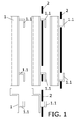
- Figure 1 is a schematic representation (and therefore without rounding radii) of the state of the art wherein the impossibility is shown of using a "hanger" type hook in its reversed position.
- the upper part of the figure shows the rail (1) in elevation and the lower part is a top plan (view seen from above) of the rail (1).
- the central elevation is that which represents the hooks (1.1) directed downwards.
- the central representation shows the rail (1) installed in the door structure (2) (section in black).
- the assembly kinematics consists of a first insertion of each of the hooks (1.1) into its corresponding window and a second downward movement which leaves the rail (1) resting on the bottom edge of the window.
- the representation on the right shows the same rail (1) rotated through 180° with its hooks (1.1) inserted in each window.
- the vertical and downward direction of the action of gravity prevents this securing from being functional.
- FIG 2 a perspective is shown in outline of a segment of rail (1) for window regulators with a means of securing consisting of a hook (1.2) according to the present invention.
- the trihedron is also represented which determines the axes of coordinates as they have been taken in this description.
- the z-axis is the vertical axis
- the y-axis will be taken as perpendicular to the main surface of the rail (1) from which emerges the hook (1.2)
- the x-axis is prolonged horizontally and parallel to this same surface.
- the hook (1.2) is formed by a partial stamping in the rail (1) plus a double bend according to axes parallel to the z-axis: a first bend that projects according to the y-axis, outwards, giving rise to what in the description has been termed the first segment (1.2.1) or root, and after the second fold is the second segment (1.2.2) or butt.
- the first segment is prolonged parallel to the y-axis and the second segment is mainly contained in the x-z plane.
- the word "mainly” is used since it can have a third fold (1.2.3) such as is shown in figure 7, also according to an axis parallel to the z-axis, which gives a small angle of inclination on the end of the hook (1.2) to allow easier entry into the corresponding window or cavity of the door structure.
- the cavity (2.1) has been defined by means of a dashed line in which in turn it is possible to distinguish two areas: an upper first area (2.1.1) and a lower second area (2.1.2) of smaller dimensions.
- the first area (2.1.1) corresponds at least to the projection of the hook (1.2) on a plane parallel to the plane with x-z coordinates giving rise to a cavity (2.1.1) which is capable of receiving the hook (1.2) when in the first operation it is inserted in the door structure.
- This section corresponds to the first segment (1.2.1) of the hook (1.2) which is that which will rest on the rim of the cavity or window (2.1) supporting the vertical loads of the rail (1).
- the window has a second area (2.1.2) which prolongs the first (2.1.1).
- This second area (2.1.2) coincides with the section of the hook (1.2) and is where the latter (1.2) is housed definitively after the downward vertical displacement.
- the assembly kinematics required for the installation of the rail (1) is the following:
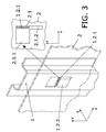
- Figure 3 is a representation of the same hook (1.2) rotated through 180° according to the y-axis by rotating the rail which holds it. A configuration results from this rotation which is equivalent to a symmetry with respect to a plane parallel to the y-z coordinates plane.
- the window or cavity (2.1) which receives the front rail has a configuration symmetrical to the window which receives the rear rail (the rear rail being the same rail as the front one to which a rotation of 180° has been applied with respect to the y-axis) with respect to the same y-z plane. It is necessary to point out that the cavity (2.1) does not have a configuration that corresponds to a rotation of 180°. This aspect is irrelevant since the important thing is that the rail (1) admits a rotation of 180° and the fastening means maintains its functionality.
- the configuration of the cavity (2.1) on the door structure (2) is what the hook requires and does not affect the advantages of the invention.
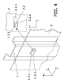
- This second example is represented in figures 4 and 5.
- the hook (1.3) is now constituted by means of a double fold. Observe that with the numbering 1.1, 1.2 and 1.3 diverse configurations of the hook are identified, the first belonging to the state of the art.
- This second segment (1.3.2) is prolonged toward one side and it is that which will serve as a butt.
- the cavity (2.2) or window is of smaller dimensions since the projection (2.2.1) of the hook on a plane parallel to the plane with x-z coordinates only has the thickness of the metal sheet with respect to the height of the cavity.
- the hatched section of the root (1.3.1) is also shown according to the middle plane of the sheet metal of the door structure where the cavity (2.2) where the hook (1.3) enters is located.
- a vertical displacement of this section (1.3.1) defines the continuation (2.2.2) of the first area (2.2.1) which completes the hollow of the cavity.
- the rail (1) after the rotation through 180° with respect to the y-axis has its hook (1.3) according to a symmetry with respect to a plane parallel to the plane with y-z coordinates. It is true that the symmetry is not established considering the cavity that remains after the stamping, however this cavity has no purpose whatever from the functional point of view. The cavity is the result of the stamping on obtaining the material from the actual metal sheet of the rail (1) and this could even not exist in the event of using another manufacturing procedure. It can be affirmed therefore that the hook (1.3) establishes such a symmetry.
- the cavity (2.2) also maintains a symmetrical relationship according to the y-z plane with that corresponding to a hook (1.3) rotated through 180°.
- the assembly kinematics is also coincident with that of the first example.
- this second area (2.1, 2.2) is immediately under where the section of the root (1.2.1, 1.3.1) of the hook is located so that the assembly kinematics, after the entry of the hook (1.2, 1.3) consists only of a downward vertical movement.
- Figure 6 shows schematically the configuration of the window for a hook (1.2) like that of the first example.
- the entry of the segment of the root (1.2.1) into the second area requires a horizontal displacement.
- This displacement has to be defined equally both in the cavity of the front rail (1) and in the rear one, since the assembly kinematics consists of a series of movements common to the two rails.
- This third example represented in figure 8 can be considered as a variation with respect to the second example. For this reason each of the parts of the hook (1.4) of this third example are identified with the same numeric references as those employed in the second example except that use is made of the reference 1.4 instead of 1.3 to distinguish one example of embodiment from the other.
- the hook (1.4) is likewise configured in as an L-shape with a first segment (1.4.1) which is prolonged according to the y-axis and a second segment (1.4.2) coplanar with the first one (1.4.1).
- the first area has a coincident bent configuration, at least the same, with the projection according to the y-axis of the hook on the x-z plane, and the second area (2.3.2) located under the first one with a configuration coincident with the section of the root (1.4.1) of the hook (1.4).
- this hook configuration falls within the invention since on being rotated through 180° it continues to be operative provided the window that receives the rotated hook has a first area configured according to the projection on the x-z plane of the hook in its new position.
Landscapes
- Window Of Vehicle (AREA)
- Power-Operated Mechanisms For Wings (AREA)
- Curtains And Furnishings For Windows Or Doors (AREA)
Priority Applications (4)
| Application Number | Priority Date | Filing Date | Title |
|---|---|---|---|
| DE602004012855T DE602004012855T2 (de) | 2004-09-14 | 2004-09-14 | Befestigungsvorrichtung für umkehrbare Schienen von Fensterhebern mit zwei Schienen |
| AT04381034T ATE391035T1 (de) | 2004-09-14 | 2004-09-14 | Befestigungsvorrichtung für umkehrbare schienen von fensterhebern mit zwei schienen |
| ES04381034T ES2303034T3 (es) | 2004-09-14 | 2004-09-14 | Medio de fijacion para carriles reversibles de elevalunas de doble carril. |
| EP04381034A EP1634742B1 (de) | 2004-09-14 | 2004-09-14 | Befestigungsvorrichtung für umkehrbare Schienen von Fensterhebern mit zwei Schienen |
Applications Claiming Priority (1)
| Application Number | Priority Date | Filing Date | Title |
|---|---|---|---|
| EP04381034A EP1634742B1 (de) | 2004-09-14 | 2004-09-14 | Befestigungsvorrichtung für umkehrbare Schienen von Fensterhebern mit zwei Schienen |
Publications (2)
| Publication Number | Publication Date |
|---|---|
| EP1634742A1 true EP1634742A1 (de) | 2006-03-15 |
| EP1634742B1 EP1634742B1 (de) | 2008-04-02 |
Family
ID=34931923
Family Applications (1)
| Application Number | Title | Priority Date | Filing Date |
|---|---|---|---|
| EP04381034A Expired - Lifetime EP1634742B1 (de) | 2004-09-14 | 2004-09-14 | Befestigungsvorrichtung für umkehrbare Schienen von Fensterhebern mit zwei Schienen |
Country Status (4)
| Country | Link |
|---|---|
| EP (1) | EP1634742B1 (de) |
| AT (1) | ATE391035T1 (de) |
| DE (1) | DE602004012855T2 (de) |
| ES (1) | ES2303034T3 (de) |
Cited By (2)
| Publication number | Priority date | Publication date | Assignee | Title |
|---|---|---|---|---|
| EP1975360A1 (de) | 2007-03-26 | 2008-10-01 | Peugeot Citroën Automobiles Sa | Vorrichtung zum Andrucken einer Führungsschiene eines Fensterhebers vor seiner Befestigung auf der inneren Auskleidung der Fahrzeugtür |
| DE102009052761B4 (de) | 2008-11-14 | 2019-03-21 | Küster Holding GmbH | Befestigungssystem für eine Führungsschiene eines Fensterhebers |
Citations (5)
| Publication number | Priority date | Publication date | Assignee | Title |
|---|---|---|---|---|
| EP0637670A2 (de) * | 1993-08-06 | 1995-02-08 | ROLTRA MORSE S.p.A. | Fensterheberprofilschiene |
| WO2001014674A1 (es) * | 1999-08-23 | 2001-03-01 | Grupo Antolin-Ingenieria, S.A. | Carril con soportes integrados |
| JP2002160522A (ja) * | 2000-11-24 | 2002-06-04 | Oi Seisakusho Co Ltd | 自動車用ドア、および自動車用窓ガラス昇降装置の取り付け構造 |
| JP2003039948A (ja) * | 2001-07-27 | 2003-02-13 | Suzuki Motor Corp | 車両用ドア |
| WO2004065738A1 (en) * | 2003-01-24 | 2004-08-05 | Intier Automotive Closures Inc. | Window regulator |
-
2004
- 2004-09-14 AT AT04381034T patent/ATE391035T1/de not_active IP Right Cessation
- 2004-09-14 EP EP04381034A patent/EP1634742B1/de not_active Expired - Lifetime
- 2004-09-14 DE DE602004012855T patent/DE602004012855T2/de not_active Expired - Fee Related
- 2004-09-14 ES ES04381034T patent/ES2303034T3/es not_active Expired - Lifetime
Patent Citations (5)
| Publication number | Priority date | Publication date | Assignee | Title |
|---|---|---|---|---|
| EP0637670A2 (de) * | 1993-08-06 | 1995-02-08 | ROLTRA MORSE S.p.A. | Fensterheberprofilschiene |
| WO2001014674A1 (es) * | 1999-08-23 | 2001-03-01 | Grupo Antolin-Ingenieria, S.A. | Carril con soportes integrados |
| JP2002160522A (ja) * | 2000-11-24 | 2002-06-04 | Oi Seisakusho Co Ltd | 自動車用ドア、および自動車用窓ガラス昇降装置の取り付け構造 |
| JP2003039948A (ja) * | 2001-07-27 | 2003-02-13 | Suzuki Motor Corp | 車両用ドア |
| WO2004065738A1 (en) * | 2003-01-24 | 2004-08-05 | Intier Automotive Closures Inc. | Window regulator |
Non-Patent Citations (2)
| Title |
|---|
| PATENT ABSTRACTS OF JAPAN vol. 2002, no. 10 10 October 2002 (2002-10-10) * |
| PATENT ABSTRACTS OF JAPAN vol. 2003, no. 06 3 June 2003 (2003-06-03) * |
Cited By (3)
| Publication number | Priority date | Publication date | Assignee | Title |
|---|---|---|---|---|
| EP1975360A1 (de) | 2007-03-26 | 2008-10-01 | Peugeot Citroën Automobiles Sa | Vorrichtung zum Andrucken einer Führungsschiene eines Fensterhebers vor seiner Befestigung auf der inneren Auskleidung der Fahrzeugtür |
| FR2914345A1 (fr) * | 2007-03-26 | 2008-10-03 | Peugeot Citroen Automobiles Sa | Dispositif de plaquage d'un rail de guidage de leve-vitre avant sa fixation sur une doublure de porte de vehicule. |
| DE102009052761B4 (de) | 2008-11-14 | 2019-03-21 | Küster Holding GmbH | Befestigungssystem für eine Führungsschiene eines Fensterhebers |
Also Published As
| Publication number | Publication date |
|---|---|
| EP1634742B1 (de) | 2008-04-02 |
| ATE391035T1 (de) | 2008-04-15 |
| ES2303034T3 (es) | 2008-08-01 |
| DE602004012855T2 (de) | 2009-04-09 |
| DE602004012855D1 (de) | 2008-05-15 |
Similar Documents
| Publication | Publication Date | Title |
|---|---|---|
| US8801055B2 (en) | Door lock mechanism | |
| EP1634742B1 (de) | Befestigungsvorrichtung für umkehrbare Schienen von Fensterhebern mit zwei Schienen | |
| JP2003184856A (ja) | 開閉体のヒンジ構造 | |
| CN114150957B (zh) | 引擎罩铰链结构 | |
| JPH10147166A (ja) | シートの取付構造 | |
| JP2018058451A (ja) | 車両のヒンジ構造 | |
| JP3360966B2 (ja) | 展望用エレベータのかご室 | |
| JP4941816B2 (ja) | ドアミラーの取付構造 | |
| JP2007126070A (ja) | 車両の室内外への部品の取付け構造 | |
| JPH0444422Y2 (de) | ||
| CN201326296Y (zh) | 车辆用外门把手的固定装置 | |
| CN221920638U (zh) | 铰链结构及车辆 | |
| CN222572048U (zh) | 车门内板结构、车门总成及车辆 | |
| JP2599829Y2 (ja) | 車両用ドア | |
| CN223689483U (zh) | 后背门锁安装总成及车辆 | |
| JPS6130903Y2 (de) | ||
| JPH06171366A (ja) | 自動車のドア | |
| JPH0642361U (ja) | 車両のドア | |
| KR0125312Y1 (ko) | 자동차 윈도우그라스 정지구조 | |
| JP2570470Y2 (ja) | 室内機の室内パネル取付構造 | |
| JP3390588B2 (ja) | 自動車のドアに関する盗難防止構造 | |
| JP2006205926A (ja) | 窓体 | |
| JPH10175446A (ja) | 自動車のドア取付構造 | |
| CN106427487B (zh) | 一种汽车前风窗安装结构及汽车 | |
| JP3707382B2 (ja) | ガラス昇降式ドアの構造 |
Legal Events
| Date | Code | Title | Description |
|---|---|---|---|
| PUAI | Public reference made under article 153(3) epc to a published international application that has entered the european phase |
Free format text: ORIGINAL CODE: 0009012 |
|
| AK | Designated contracting states |
Kind code of ref document: A1 Designated state(s): AT BE BG CH CY CZ DE DK EE ES FI FR GB GR HU IE IT LI LU MC NL PL PT RO SE SI SK TR |
|
| AX | Request for extension of the european patent |
Extension state: AL HR LT LV MK |
|
| 17P | Request for examination filed |
Effective date: 20060818 |
|
| AKX | Designation fees paid |
Designated state(s): AT BE BG CH CY CZ DE DK EE ES FI FR GB GR HU IE IT LI LU MC NL PL PT RO SE SI SK TR |
|
| 17Q | First examination report despatched |
Effective date: 20070713 |
|
| GRAP | Despatch of communication of intention to grant a patent |
Free format text: ORIGINAL CODE: EPIDOSNIGR1 |
|
| GRAS | Grant fee paid |
Free format text: ORIGINAL CODE: EPIDOSNIGR3 |
|
| GRAA | (expected) grant |
Free format text: ORIGINAL CODE: 0009210 |
|
| AK | Designated contracting states |
Kind code of ref document: B1 Designated state(s): AT BE BG CH CY CZ DE DK EE ES FI FR GB GR HU IE IT LI LU MC NL PL PT RO SE SI SK TR |
|
| REG | Reference to a national code |
Ref country code: GB Ref legal event code: FG4D |
|
| REG | Reference to a national code |
Ref country code: CH Ref legal event code: EP Ref country code: IE Ref legal event code: FG4D |
|
| REF | Corresponds to: |
Ref document number: 602004012855 Country of ref document: DE Date of ref document: 20080515 Kind code of ref document: P |
|
| REG | Reference to a national code |
Ref country code: ES Ref legal event code: FG2A Ref document number: 2303034 Country of ref document: ES Kind code of ref document: T3 |
|
| PG25 | Lapsed in a contracting state [announced via postgrant information from national office to epo] |
Ref country code: SI Free format text: LAPSE BECAUSE OF FAILURE TO SUBMIT A TRANSLATION OF THE DESCRIPTION OR TO PAY THE FEE WITHIN THE PRESCRIBED TIME-LIMIT Effective date: 20080402 |
|
| NLV1 | Nl: lapsed or annulled due to failure to fulfill the requirements of art. 29p and 29m of the patents act | ||
| PG25 | Lapsed in a contracting state [announced via postgrant information from national office to epo] |
Ref country code: FI Free format text: LAPSE BECAUSE OF FAILURE TO SUBMIT A TRANSLATION OF THE DESCRIPTION OR TO PAY THE FEE WITHIN THE PRESCRIBED TIME-LIMIT Effective date: 20080402 Ref country code: BG Free format text: LAPSE BECAUSE OF FAILURE TO SUBMIT A TRANSLATION OF THE DESCRIPTION OR TO PAY THE FEE WITHIN THE PRESCRIBED TIME-LIMIT Effective date: 20080702 Ref country code: PT Free format text: LAPSE BECAUSE OF FAILURE TO SUBMIT A TRANSLATION OF THE DESCRIPTION OR TO PAY THE FEE WITHIN THE PRESCRIBED TIME-LIMIT Effective date: 20080903 Ref country code: NL Free format text: LAPSE BECAUSE OF FAILURE TO SUBMIT A TRANSLATION OF THE DESCRIPTION OR TO PAY THE FEE WITHIN THE PRESCRIBED TIME-LIMIT Effective date: 20080402 |
|
| PG25 | Lapsed in a contracting state [announced via postgrant information from national office to epo] |
Ref country code: AT Free format text: LAPSE BECAUSE OF FAILURE TO SUBMIT A TRANSLATION OF THE DESCRIPTION OR TO PAY THE FEE WITHIN THE PRESCRIBED TIME-LIMIT Effective date: 20080402 Ref country code: PL Free format text: LAPSE BECAUSE OF FAILURE TO SUBMIT A TRANSLATION OF THE DESCRIPTION OR TO PAY THE FEE WITHIN THE PRESCRIBED TIME-LIMIT Effective date: 20080402 |
|
| ET | Fr: translation filed | ||
| PG25 | Lapsed in a contracting state [announced via postgrant information from national office to epo] |
Ref country code: CZ Free format text: LAPSE BECAUSE OF FAILURE TO SUBMIT A TRANSLATION OF THE DESCRIPTION OR TO PAY THE FEE WITHIN THE PRESCRIBED TIME-LIMIT Effective date: 20080402 Ref country code: DK Free format text: LAPSE BECAUSE OF FAILURE TO SUBMIT A TRANSLATION OF THE DESCRIPTION OR TO PAY THE FEE WITHIN THE PRESCRIBED TIME-LIMIT Effective date: 20080402 Ref country code: SE Free format text: LAPSE BECAUSE OF FAILURE TO SUBMIT A TRANSLATION OF THE DESCRIPTION OR TO PAY THE FEE WITHIN THE PRESCRIBED TIME-LIMIT Effective date: 20080702 |
|
| PLBE | No opposition filed within time limit |
Free format text: ORIGINAL CODE: 0009261 |
|
| STAA | Information on the status of an ep patent application or granted ep patent |
Free format text: STATUS: NO OPPOSITION FILED WITHIN TIME LIMIT |
|
| PG25 | Lapsed in a contracting state [announced via postgrant information from national office to epo] |
Ref country code: RO Free format text: LAPSE BECAUSE OF FAILURE TO SUBMIT A TRANSLATION OF THE DESCRIPTION OR TO PAY THE FEE WITHIN THE PRESCRIBED TIME-LIMIT Effective date: 20080402 Ref country code: BE Free format text: LAPSE BECAUSE OF FAILURE TO SUBMIT A TRANSLATION OF THE DESCRIPTION OR TO PAY THE FEE WITHIN THE PRESCRIBED TIME-LIMIT Effective date: 20080402 Ref country code: SK Free format text: LAPSE BECAUSE OF FAILURE TO SUBMIT A TRANSLATION OF THE DESCRIPTION OR TO PAY THE FEE WITHIN THE PRESCRIBED TIME-LIMIT Effective date: 20080402 |
|
| 26N | No opposition filed |
Effective date: 20090106 |
|
| PG25 | Lapsed in a contracting state [announced via postgrant information from national office to epo] |
Ref country code: EE Free format text: LAPSE BECAUSE OF FAILURE TO SUBMIT A TRANSLATION OF THE DESCRIPTION OR TO PAY THE FEE WITHIN THE PRESCRIBED TIME-LIMIT Effective date: 20080402 Ref country code: MC Free format text: LAPSE BECAUSE OF NON-PAYMENT OF DUE FEES Effective date: 20080930 |
|
| REG | Reference to a national code |
Ref country code: CH Ref legal event code: PL |
|
| GBPC | Gb: european patent ceased through non-payment of renewal fee |
Effective date: 20080914 |
|
| PG25 | Lapsed in a contracting state [announced via postgrant information from national office to epo] |
Ref country code: IE Free format text: LAPSE BECAUSE OF NON-PAYMENT OF DUE FEES Effective date: 20080915 |
|
| PG25 | Lapsed in a contracting state [announced via postgrant information from national office to epo] |
Ref country code: IT Free format text: LAPSE BECAUSE OF FAILURE TO SUBMIT A TRANSLATION OF THE DESCRIPTION OR TO PAY THE FEE WITHIN THE PRESCRIBED TIME-LIMIT Effective date: 20080402 Ref country code: DE Free format text: LAPSE BECAUSE OF NON-PAYMENT OF DUE FEES Effective date: 20090401 |
|
| PG25 | Lapsed in a contracting state [announced via postgrant information from national office to epo] |
Ref country code: CY Free format text: LAPSE BECAUSE OF FAILURE TO SUBMIT A TRANSLATION OF THE DESCRIPTION OR TO PAY THE FEE WITHIN THE PRESCRIBED TIME-LIMIT Effective date: 20080402 |
|
| PG25 | Lapsed in a contracting state [announced via postgrant information from national office to epo] |
Ref country code: CH Free format text: LAPSE BECAUSE OF NON-PAYMENT OF DUE FEES Effective date: 20080930 Ref country code: LI Free format text: LAPSE BECAUSE OF NON-PAYMENT OF DUE FEES Effective date: 20080930 |
|
| PG25 | Lapsed in a contracting state [announced via postgrant information from national office to epo] |
Ref country code: GB Free format text: LAPSE BECAUSE OF NON-PAYMENT OF DUE FEES Effective date: 20080914 |
|
| PG25 | Lapsed in a contracting state [announced via postgrant information from national office to epo] |
Ref country code: HU Free format text: LAPSE BECAUSE OF FAILURE TO SUBMIT A TRANSLATION OF THE DESCRIPTION OR TO PAY THE FEE WITHIN THE PRESCRIBED TIME-LIMIT Effective date: 20081003 Ref country code: LU Free format text: LAPSE BECAUSE OF NON-PAYMENT OF DUE FEES Effective date: 20080914 |
|
| PG25 | Lapsed in a contracting state [announced via postgrant information from national office to epo] |
Ref country code: TR Free format text: LAPSE BECAUSE OF FAILURE TO SUBMIT A TRANSLATION OF THE DESCRIPTION OR TO PAY THE FEE WITHIN THE PRESCRIBED TIME-LIMIT Effective date: 20080402 |
|
| PG25 | Lapsed in a contracting state [announced via postgrant information from national office to epo] |
Ref country code: GR Free format text: LAPSE BECAUSE OF FAILURE TO SUBMIT A TRANSLATION OF THE DESCRIPTION OR TO PAY THE FEE WITHIN THE PRESCRIBED TIME-LIMIT Effective date: 20080703 |
|
| PGFP | Annual fee paid to national office [announced via postgrant information from national office to epo] |
Ref country code: ES Payment date: 20130722 Year of fee payment: 10 |
|
| PGFP | Annual fee paid to national office [announced via postgrant information from national office to epo] |
Ref country code: FR Payment date: 20130730 Year of fee payment: 10 |
|
| REG | Reference to a national code |
Ref country code: FR Ref legal event code: ST Effective date: 20150529 |
|
| PG25 | Lapsed in a contracting state [announced via postgrant information from national office to epo] |
Ref country code: FR Free format text: LAPSE BECAUSE OF NON-PAYMENT OF DUE FEES Effective date: 20140930 |
|
| REG | Reference to a national code |
Ref country code: ES Ref legal event code: FD2A Effective date: 20160105 |
|
| PG25 | Lapsed in a contracting state [announced via postgrant information from national office to epo] |
Ref country code: ES Free format text: LAPSE BECAUSE OF NON-PAYMENT OF DUE FEES Effective date: 20140915 |