EP1635129A2 - Climatiseur - Google Patents
Climatiseur Download PDFInfo
- Publication number
- EP1635129A2 EP1635129A2 EP05019588A EP05019588A EP1635129A2 EP 1635129 A2 EP1635129 A2 EP 1635129A2 EP 05019588 A EP05019588 A EP 05019588A EP 05019588 A EP05019588 A EP 05019588A EP 1635129 A2 EP1635129 A2 EP 1635129A2
- Authority
- EP
- European Patent Office
- Prior art keywords
- heat exchanger
- interior
- absolute value
- interior heat
- air
- Prior art date
- Legal status (The legal status is an assumption and is not a legal conclusion. Google has not performed a legal analysis and makes no representation as to the accuracy of the status listed.)
- Granted
Links
Images

Classifications
-
- F—MECHANICAL ENGINEERING; LIGHTING; HEATING; WEAPONS; BLASTING
- F25—REFRIGERATION OR COOLING; COMBINED HEATING AND REFRIGERATION SYSTEMS; HEAT PUMP SYSTEMS; MANUFACTURE OR STORAGE OF ICE; LIQUEFACTION SOLIDIFICATION OF GASES
- F25B—REFRIGERATION MACHINES, PLANTS OR SYSTEMS; COMBINED HEATING AND REFRIGERATION SYSTEMS; HEAT PUMP SYSTEMS
- F25B13/00—Compression machines, plants or systems, with reversible cycle
-
- F—MECHANICAL ENGINEERING; LIGHTING; HEATING; WEAPONS; BLASTING
- F25—REFRIGERATION OR COOLING; COMBINED HEATING AND REFRIGERATION SYSTEMS; HEAT PUMP SYSTEMS; MANUFACTURE OR STORAGE OF ICE; LIQUEFACTION SOLIDIFICATION OF GASES
- F25B—REFRIGERATION MACHINES, PLANTS OR SYSTEMS; COMBINED HEATING AND REFRIGERATION SYSTEMS; HEAT PUMP SYSTEMS
- F25B2313/00—Compression machines, plants or systems with reversible cycle not otherwise provided for
- F25B2313/007—Compression machines, plants or systems with reversible cycle not otherwise provided for three pipes connecting the outdoor side to the indoor side with multiple indoor units
-
- F—MECHANICAL ENGINEERING; LIGHTING; HEATING; WEAPONS; BLASTING
- F25—REFRIGERATION OR COOLING; COMBINED HEATING AND REFRIGERATION SYSTEMS; HEAT PUMP SYSTEMS; MANUFACTURE OR STORAGE OF ICE; LIQUEFACTION SOLIDIFICATION OF GASES
- F25B—REFRIGERATION MACHINES, PLANTS OR SYSTEMS; COMBINED HEATING AND REFRIGERATION SYSTEMS; HEAT PUMP SYSTEMS
- F25B2313/00—Compression machines, plants or systems with reversible cycle not otherwise provided for
- F25B2313/023—Compression machines, plants or systems with reversible cycle not otherwise provided for using multiple indoor units
- F25B2313/0231—Compression machines, plants or systems with reversible cycle not otherwise provided for using multiple indoor units with simultaneous cooling and heating
-
- F—MECHANICAL ENGINEERING; LIGHTING; HEATING; WEAPONS; BLASTING
- F25—REFRIGERATION OR COOLING; COMBINED HEATING AND REFRIGERATION SYSTEMS; HEAT PUMP SYSTEMS; MANUFACTURE OR STORAGE OF ICE; LIQUEFACTION SOLIDIFICATION OF GASES
- F25B—REFRIGERATION MACHINES, PLANTS OR SYSTEMS; COMBINED HEATING AND REFRIGERATION SYSTEMS; HEAT PUMP SYSTEMS
- F25B2313/00—Compression machines, plants or systems with reversible cycle not otherwise provided for
- F25B2313/025—Compression machines, plants or systems with reversible cycle not otherwise provided for using multiple outdoor units
-
- F—MECHANICAL ENGINEERING; LIGHTING; HEATING; WEAPONS; BLASTING
- F25—REFRIGERATION OR COOLING; COMBINED HEATING AND REFRIGERATION SYSTEMS; HEAT PUMP SYSTEMS; MANUFACTURE OR STORAGE OF ICE; LIQUEFACTION SOLIDIFICATION OF GASES
- F25B—REFRIGERATION MACHINES, PLANTS OR SYSTEMS; COMBINED HEATING AND REFRIGERATION SYSTEMS; HEAT PUMP SYSTEMS
- F25B2700/00—Sensing or detecting of parameters; Sensors therefor
- F25B2700/21—Temperatures
- F25B2700/2106—Temperatures of fresh outdoor air
Definitions
- the present invention relates to an air conditioner including a first interior heat exchanger for heating an air with a refrigerant, a second interior heat exchanger for cooling the air with the refrigerant, and an exterior heat exchanger for required one of taking a heat energy into the refrigerant and radiating the heat energy from the refrigerant as occasion demands.
- a gaseous refrigerant pressurized by a compressor is fed to an interior heat exchanger for heating a room air so that the gaseous refrigerant is condensed to change to a liquid refrigerant, and a gaseous refrigerant pressurized by another compressor is fed to an exterior heat exchanger to be condensed and subsequently fed to another interior heat exchanger for cooling the room air so that the refrigerant condensed to be liquefied by the exterior heat exchanger is evaporated in the another interior heat exchanger.
- An object of the present invention is to provide an air conditioner by which an operating efficiency is improved with preventing or restraining an excessive cooling capacity or performance of the first interior heat exchanger and an insufficient heating capacity or performance of the second interior heat exchanger when a temperature of an exterior air is deemed to be not more than a predetermined temperature to cause an excessive heating performance for the exterior air of the exterior heat exchanger with decreasing the heating capacity or performance of the second interior heat exchanger.
- an air conditioner comprising, an exterior heat exchanger capable of performing a heat exchange between a refrigerant and an exterior air and including an adjustable valve whose opening area (for passing the refrigerant through the adjustable valve) is variable so that the adjustable valve is usable as desired (or selected) one of an expansion valve for the refrigerant to use the exterior heat exchanger as an evaporator and a passage for the refrigerant to use the exterior heat exchanger as a condenser, a first interior heat exchanger capable of performing a heat exchange between the refrigerant and an interior air to be cooled (in such a manner that a difference between an actual temperature of the interior air to be cooled and a desirable temperature of the interior air to be cooled is automatically or manually decreased, minimized or kept within a desirable range, with a change of a rate of heat exchange energy amount for cooling with respect to a time proceeding, that is, a change of the heat exchange energy amount for cooling per every unit time in accordance with the difference between the actual temperature of the interior
- the below mentioned various controls does not need necessarily to be performed with calculation in the absolute values(s), and may be performed when the physical conditions or situations defined with using the absolute values(s) are actually satisfied or fulfilled, irrespective of whether or not the calculation in the absolute values(s) is performed. That is, the absolute values(s) is used to definitely clarify the physical conditions or situations on which the control is performed, but is not used to restrict the scopes of the below mentioned various controls to respective calculating manners with using the absolute values(s).
- valve means sets the flow course of the refrigerant at the cooling main course when a desirable amount in absolute value of thermal energy per unit time to be exchanged by the first interior heat exchanger is greater than a desirable amount in absolute value of thermal energy per unit time to be exchanged by the second interior heat exchanger, and sets the flow course of the refrigerant at the heating main course when the desirable amount in absolute value of thermal energy per unit time to be exchanged by the second interior heat exchanger is greater than the desirable amount in absolute value of thermal energy per unit time to be exchanged by the first interior heat exchanger.
- valve means changes the flow course of the refrigerant from the cooling main course to the heating main course when a temperature of the exterior air is not more than a predetermined temperature, and a difference in absolute value between a desirable amount in absolute value of thermal energy per unit time to be exchanged by the first interior heat exchanger and a desirable amount in absolute value of thermal energy per unit time to be exchanged by the second interior heat exchanger is not more than a predetermined value.
- valve means changes the flow course of the refrigerant from the cooling main course to the heating main course when a difference in absolute value between a desirable amount in absolute value of thermal energy per unit time to be exchanged by the first interior heat exchanger and a desirable amount in absolute value of heat energy per unit time to be exchanged by the second interior heat exchanger is not more than a predetermined value, and a difference in absolute value between an amount in absolute value of heat energy per unit time actually exchanged by the first interior heat exchanger and an amount in absolute value of heat energy per unit time actually exchanged by the second interior heat exchanger less than the amount in absolute value of heat energy per unit time actually exchanged by the first interior heat exchanger is more than a predetermined reference value.
- a difference in absolute value between an actual temperature of the interior air to be cooled by the first interior heat exchanger and a desirable temperature of the interior air to be cooled by the first interior heat exchanger lower than the actual temperature of the interior air to be cooled by the first interior heat exchanger is a value corresponding to the desirable amount in absolute value of thermal energy per unit time to be exchanged by the first interior heat exchanger
- a difference in absolute value between a desirable temperature of the interior air to be heated by the second interior heat exchanger and an actual temperature of the interior air to be heated by the second interior heat exchanger lower than the desirable temperature of the interior air to be heated by the second interior heat exchanger is a value corresponding to the desirable amount in absolute value of thermal energy per unit time to be exchanged by the second interior heat exchanger.
- a product of a flow rate of the interior air flowing through the first interior heat exchanger and a difference in absolute value between an actual temperature of the interior air to be cooled by the first interior heat exchanger and a desirable temperature of the interior air to be cooled by the first interior heat exchanger lower than the actual temperature of the interior air to be cooled by the first interior heat exchanger is a value corresponding to the desirable amount in absolute value of thermal energy per unit time to be exchanged by the first interior heat exchanger
- a product of a flow rate of the interior air flowing through the second interior heat exchanger and a difference in absolute value between an actual temperature of the interior air to be heated by the second interior heat exchanger and a desirable temperature of the interior air to be heated by the second interior heat exchanger higher than the actual temperature of the interior air to be heated by the second interior heat exchanger is a value corresponding to the desirable amount in absolute value of thermal
- the desirable amount in absolute value of thermal energy per unit time to be exchanged by the at least one of the first and second interior heat exchangers is a total amount of desirable amounts in absolute value of thermal energy per unit time to be exchanged by the interior sub-heat exchangers respectively.
- a pressure of the refrigerant evaporated by the first interior heat exchanger is less than a first comparison value and a pressure of the refrigerant condensed by the second interior heat exchanger is less than a second comparison value, that the difference in absolute value between the amount in absolute value of heat energy per unit time actually exchanged by the first interior heat exchanger and the amount in absolute value of heat energy per unit time actually exchanged by the second interior heat exchanger less than the amount in absolute value of heat energy per unit time actually exchanged by the first interior heat exchanger is more than the predetermined reference value.
- the difference in absolute value in temperature between the interior air to be taken into the first interior heat exchanger and the interior air discharged from the first interior heat exchanger is the smallest one of differences in absolute value in temperature between the interior airs to be taken into the respective first interior sub-heat exchangers and the interior airs discharged from the respective first interior sub-heat exchangers.
- the second interior heat exchanger has a plurality of second interior sub-heat exchangers connected in parallel to each other, and the difference in absolute value in temperature between the interior air to be taken into the second interior heat exchanger and the interior air discharged from the second interior heat exchanger is the greatest one of differences in absolute value in temperature between the interior airs to be taken into the respective second interior sub-heat exchangers and the interior airs discharged from the respective second interior sub-heat exchangers.
- a difference in temperature in absolute value between the interior air to be taken into the first interior heat exchanger and the interior air discharged from the first interior heat exchanger is a value corresponding to the amount in absolute value of heat energy per unit time actually exchanged by the first interior heat exchanger
- a difference in temperature in absolute value between the interior air to be taken into the second interior heat exchanger and the interior air discharged from the second interior heat exchanger is a value corresponding to the amount in absolute value of heat energy per unit time actually exchanged by the second interior heat exchanger.
- a product of a flow rate of the interior air flowing through the first interior heat exchanger and a difference in temperature in absolute value between the interior air to be taken into the first interior heat exchanger and the interior air discharged from the first interior heat exchanger is a value corresponding to the amount in absolute value of heat energy per unit time actually exchanged by the first interior heat exchanger
- a product of a flow rate of the interior air flowing through the second interior heat exchanger and a difference in temperature in absolute value between the interior air to be taken into the second interior heat exchanger and the interior air discharged from the second interior heat exchanger is a value corresponding to the amount in absolute value of heat energy per unit time actually exchanged by the second interior heat exchanger.
- a difference in temperature in absolute value between the refrigerant taken into the first interior heat exchanger and the refrigerant discharged from the first interior heat exchanger is a value corresponding to the amount in absolute value of heat energy per unit time actually exchanged by the first interior heat exchanger
- a difference in temperature in absolute value between the refrigerant taken into the second interior heat exchanger and the refrigerant discharged from the second interior heat exchanger is a value corresponding to the amount in absolute value of heat energy per unit time actually exchanged by the second interior heat exchanger.
- a product of a mass flow rate of the refrigerant flowing through the first interior heat exchanger and a difference in temperature in absolute value between the refrigerant taken into the first interior heat exchanger and the refrigerant discharged from the first interior heat exchanger is a value corresponding to the amount in absolute value of heat energy per unit time actually exchanged by the first interior heat exchanger
- a product of a mass flow rate of the refrigerant flowing through the second interior heat exchanger and a difference in temperature in absolute value between the refrigerant taken into the second interior heat exchanger and the refrigerant discharged from the second interior heat exchanger is a value corresponding to the amount in absolute value of heat energy per unit time actually exchanged by the second interior heat exchanger.
- the exterior heat exchanger has a thermistor for measuring a temperature of the refrigerant in the exterior heat exchanger, and at which the exterior heat exchanger is used the evaporator condition or condenser condition is detected from the temperature of the refrigerant measured by the thermistor so that when the measured temperature of the refrigerant is lower than a predetermined temperature, the exterior heat exchanger is deemed to be used as the evaporator, and when the measured temperature of the refrigerant is not lower than the predetermined temperature, the exterior heat exchanger is deemed to be used as the condenser. It is preferable that the detected conditions of the four-way valve and exterior heat exchanger are indicated on at least one of a remote controller for controlling the air
- An air conditioner may comprise an exterior unit having a compressor (1), a plurality of four-way valves (3a, 3b) connected to the compressor to change a flow direction of a refrigerant, a plurality of exterior heat exchangers (2a, 2b), and exterior electronic expansion valves (4a, 4b) connected to the exterior heat exchangers respectively, and a plurality of interior units having respective interior heat exchangers, respective interior electronic expansion valves and respective shut-off valves and connected to the exterior heat exchangers through a pipe for refrigerant of gas state and a pipe for refrigerant of liquid state wherein a refrigerant cycle having one of the interior units operable to cool an interior air and the other one of the interior units operable to heat the interior air is formed, and an operation of the air conditioner is changed to a cooling main mode with using the exterior heat exchanger as a condenser when a cooling load is greater than a heating load, and to a heating main mode with using the exterior heat exchanger as an evaporator when the heating load
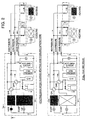
- Figs. 1 and 2 show a refrigerating cycle capable of simultaneously heating and cooling
- an upper drawing of fig. 1 shows a full cooling mode
- a lower drawing thereof shows a cooling main mode during simultaneous heating and cooling operations
- an upper drawing of fig. 2 shows a heating main mode during simultaneous heating and cooling operations
- a lower drawing thereof shows a full heating mode
- an arrow mark shows a flow of a refrigerant.
- the refrigerating cycle is constituted by a compressor 1, a plurality of exterior heat exchangers 2a and 2b, exterior electronically controlled expansion valves 4a and 4b attached to the exterior heat exchangers 2a and 2b, a check valve 5, an exterior unit including four-way valves 3a and 3b for changing a refrigerant flowing route, and at least two, for example, k interior units which are connected to the exterior unit through gas and liquid pipes and include respective interior heat exchangers 6a and 6b with respective interior electronically controlled expansion valves 7a and 7b and respective pairs of valves 8a and 9a and valves 8b and 9b (one filled with black is closed, and one filled with white is opened).
- the gas refrigerant discharged from the compressor 1 is fed to the exterior heat exchanger 2b and interior heat exchanger 6b as condensers so that it is changed to the liquid refrigerant through the heat exchange, and subsequently the liquid refrigerant is fed to the interior heat exchanger 6a as an evaporator.
- the liquid refrigerant is vaporized in the interior heat exchanger 6a, and the vaporized refrigerant is recovered into the compressor 1.
- the refrigerant discharged from the compressor 1 flows into the interior heat exchanger 6b as the condenser to perform the heat exchange, and the liquefied refrigerant is fed to the exterior heat exchanger 2a and interior heat exchanger 6a as the evaporator, and the refrigerant vaporized by the heat exchange by them returns to the compressor 1.
- a heat exchange energy amount thermally exchanged by the interior heat exchanger 6b as the condenser is balanced with a heat exchange energy amount thermally exchanged by the interior heat exchanger 6a and exterior heat exchanger 2a as the evaporator.
- an intended purpose and/or capacity of the exterior heat exchanger is changed to drive both the interior room heater and interior room cooler, and a difference in amount of exchanged thermal energy between the interior cooling and the interior heating is compensated by the exterior heat exchanger to form the refrigerating cycle.
- an exterior heat exchange amount Qo for other than a thermal input from the compressor is not necessary, and may be zero, so that if the exterior heat exchange amount Qo by the exterior heat exchanger is more than zero as performed in the prior art, the heat exchange amount Qci of the interior heat exchanger as the condenser is decreased by the heat exchange amount Qco of the exterior heat exchanger as the condenser when the cooling main mode. Further, in the heating main mode, the heat exchange amount Qei of the interior heat exchanger as the evaporator is decreased by the heat exchange amount Qeo of the exterior heat exchanger as the evaporator. When the exterior temperature is significantly low or high to increase the heat exchange amount by the exterior heat exchanger, an effect thereby increases.
- the heat exchange amount of the interior heat exchanger for cooling the room air and the heat exchange amount of the interior heat exchanger for heating the room air are balanced with each other except for the power Pc applied by the compressor to the refrigerant, an enthalpy necessary for the required cooling capacity is supplied from the interior heat exchanger 6b for heating the room air.
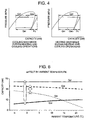
- the refrigerant flows through the exterior unit, the high pressure and high temperature gas refrigerant flows through the exterior heat exchanger 2b to generate the heat exchange amount Qco radiated from the exterior heat exchanger as the condenser.
- the heat exchange amount Qt of the heat energy absorbing side in the refrigerating cycle is kept unchanged, since the enthalpy necessary for the required cooling capacity is a total amount of the heat exchange amount Qco of the exterior heat exchanger as the condenser and the heat exchange amount Qci of the interior heat exchanger as the condenser, the heat exchange amount Qci of the interior heat exchanger as the condenser is smaller than the heat exchange amount Qt of the heat energy absorbing side by the heat exchange amount Qco of the exterior heat exchanger as the condenser.
- This situation occurs when the ambient temperature is low to accelerate the heat radiation of the exterior heat exchanger 2b as the condenser. Therefore, an efficiency of operation for simultaneous heating and cooling is low.
- the heat exchange amount Qci of the interior heat exchanger as the condenser becomes great.
- the input power Pc from the compressor when Qt is kept unchanged, the heat exchange amount Qei of the interior heat exchanger as the evaporator and the input power Pc from the compressor change inversely with respect to each other, so that the heat exchange amount Qei of the interior heat exchanger as the evaporator is decreased by the input power Pc from the compressor.
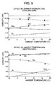
- the heat exchange amount Qeo of the exterior heat exchanger as the evaporator exists and the heat exchange amount Qt of the heat energy emitting side in the refrigerating cycle is kept unchanged, since the enthalpy difference necessary for the required heating capacity is a total amount of the heat exchange amount Qeo of the exterior heat exchanger as the evaporator, the heat exchange amount Qei of the interior heat exchanger as the evaporator and the input power Pc from the compressor, the heat exchange amount Qei of the interior heat exchanger as the evaporator is smaller than the heat exchange amount Qt of the heat energy emitting side by the heat exchange amount Qeo of the exterior heat exchanger as the evaporator.
- the heat exchange amount Qeo of the exterior heat exchanger as the evaporator and the heat exchange amount Qei of the interior heat exchanger as the evaporator change inversely with respect to each other, so that the heat exchange amount Qei of the interior heat exchanger as the evaporator is decreased by the heat exchange amount Qeo of the exterior heat exchanger as the evaporator,
- This situation occurs when the ambient temperature is high to accelerate the heat absorption of the exterior heat exchanger as the evaporator, and increase the heat exchange amount Qeo of the exterior heat exchanger as the evaporator, the heat exchange amount Qei of the interior heat exchanger as the evaporator is decreased. Therefore, an efficiency of operation for simultaneous heating and cooling is low.
- the heating capacity is insufficient at the low ambient temperature in the cooling main mode, and cooling capacity is insufficient at the high ambient temperature in the heating main mode, so that an input power for the compressor needs to be increased to compensate this insufficiency of the capacity, and an operating efficiency during simultaneous heating and cooling is decreased.
- the operating mode is changed between the heating main mode and cooling main mode in accordance with a detection of insufficiency of the heating or cooling capacity on the basis of a decision value for each of the capacity of the interior heat exchanger for cooling the room air and the capacity of the interior heat exchanger for heating the room air, in addition to a judgment on the basis of a rate between the cooling load and heating load.
- the insufficiency of the heating capacity is detected so that the cooling main mode is replaced by the heating main mode in which the exterior heat exchanger is used as the evaporator forming the refrigerating cycle.
- the heat exchange amount of the exterior heat exchanger is decreased to prevent the condensing pressure from decreasing, so that the capacity for heating the room air is maintained, and an excessive decrease of the evaporating pressure is prevented. Therefore, the cooling capacity is restrained from becoming excessive when the ambient temperature is low, and the efficiency for simultaneous heating and cooling is increased.
- the heat exchange amount Qco of the exterior heat exchanger as the condenser is zero, the heat exchange is performed only by the interior heat exchanger as the evaporator and the interior heat exchanger as the condenser, so that the heat radiation or heat absorption added by the exterior heat exchanger does not exist and the whole of the heat energy circulates between the interior heat exchangers to increase the operating efficiency.
- the operating efficiency in simultaneous heating and cooling is indicated by COP (5) calculated by formula 1
- the heat exchange amounts in the modes are calculated by formula 2 and 3 respectively.
- the operating efficiency (the cooling main mode) and the operating efficiency (the heating main mode) are calculated along the formulas 4 and 5.
- a change from the cooling main mode to the heating main mode is brought about in the following condition.
- a change from the heating main mode to the cooling main mode is brought about in the following condition.
- the operating mode is changed to the heating main mode.
- the operating mode is changed to the heating main mode. (condition C7-3) ⁇ Tcmin / ⁇ Thmax > 2.3 (and preferably at least four minute elapse after changing the operating mode)
- the operating mode is changed from the cooling main mode to the heating main mode to improve a margin or spare operating capacity, an amenity and the operating efficiency.
- the cooling capacitance is insufficient and the heating capacitance is excessive, the operating mode is changed from the heating main mode to the cooling main mode.
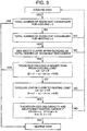
- Fig. 3 shows a control flow chart for change from the cooling main mode to the heating main mode on the basis of the condition (C7-1), and at first, during the cooling main mode, a number of the interior heat exchanger(s) being operating to cool the air is detected, and when the number of the interior heat exchanger(s) being operating to cool the air is zero, the operating mode is changed to the heating main mode.
- the load for cooling the room air and the load for heating the room air are measured.
- the load for cooling the room air and the load for heating the room air are measured, and subsequently when the load for cooling the room air is smaller the load for heating the room air, that is, L H (the total amount of the heat exchange amounts of the cooling loads of the interior heat exchanger(s) for cooling the air) - L R (the total amount of the heat exchange amounts of the heating loads of the interior heat exchanger(s) for heating the air) is smaller than a predetermined value B, the operating mode is changed to the heating main mode.
- the load for cooling the room air and the load for heating the room air are measured, and when the the load for cooling the room air and the load for heating the room air are substantially equal to each other and ⁇ Tcmin > 12 and ⁇ Thmax ⁇ 15, the operating mode is changed from the cooling main mode to the heating main mode.
- the operating efficiency for simultaneous heating and cooling is improved, and the performed operating mode is indicated on a remote controller for controlling the exterior heat exchanger and/or the interior heat exchangers.
- a detection of the operating mode to be indicated is performed from conditions of the four-way valves 3a and 3b and the exterior heat exchangers (evaporators or condensers) 2a and 2b.
- the four-way valves 3a and 3b ON/OFF situations thereof are detected from electric currents of the four-way valve coils, and regarding the exterior heat exchangers 2a and 2b, the refrigerant temperatures are measured by thermistors attached to inlets of the exterior heat exchangers, so that when the temperature is high, they are deemed to be the condensers and when the temperature is low, they are deemed to be the evaporators. From a combination of the using purposes of these four-way valves and the exterior heat exchangers, which operating mode is selected is detected.
- the efficiency of simultaneous heating and cooling is increased to improve an yearly power consumption efficiency such as an year-round power consumption efficiency determined along JIS C 9612 and JRA4055 so that CO 2 discharge is decreased and an amount of the refrigerant used in the air conditioner is decreased.
Landscapes
- Engineering & Computer Science (AREA)
- Physics & Mathematics (AREA)
- Mechanical Engineering (AREA)
- Thermal Sciences (AREA)
- General Engineering & Computer Science (AREA)
- Air Conditioning Control Device (AREA)
- Compression-Type Refrigeration Machines With Reversible Cycles (AREA)
- Air Filters, Heat-Exchange Apparatuses, And Housings Of Air-Conditioning Units (AREA)
Applications Claiming Priority (1)
| Application Number | Priority Date | Filing Date | Title |
|---|---|---|---|
| JP2004260403A JP4399667B2 (ja) | 2004-09-08 | 2004-09-08 | 空気調和機 |
Publications (3)
| Publication Number | Publication Date |
|---|---|
| EP1635129A2 true EP1635129A2 (fr) | 2006-03-15 |
| EP1635129A3 EP1635129A3 (fr) | 2017-01-11 |
| EP1635129B1 EP1635129B1 (fr) | 2018-11-21 |
Family
ID=35473110
Family Applications (1)
| Application Number | Title | Priority Date | Filing Date |
|---|---|---|---|
| EP05019588.2A Expired - Lifetime EP1635129B1 (fr) | 2004-09-08 | 2005-09-08 | Climatiseur |
Country Status (3)
| Country | Link |
|---|---|
| EP (1) | EP1635129B1 (fr) |
| JP (1) | JP4399667B2 (fr) |
| ES (1) | ES2699190T3 (fr) |
Cited By (8)
| Publication number | Priority date | Publication date | Assignee | Title |
|---|---|---|---|---|
| EP1703230A3 (fr) * | 2005-02-17 | 2009-02-25 | LG Electronics Inc. | Appareil de climatisation d'air à fonctions multiples et son procédé de commande |
| WO2009103470A1 (fr) * | 2008-02-21 | 2009-08-27 | Carrier Corporation | Système de réfrigération |
| GB2422653B (en) * | 2005-01-10 | 2011-03-02 | Arctic Circle Ltd | Refrigeration apparatus having a heating capability during cold weather |
| CN102102920A (zh) * | 2009-12-22 | 2011-06-22 | 三星电子株式会社 | 热泵设备及其室外单元 |
| CN104515195A (zh) * | 2013-09-26 | 2015-04-15 | 海尔集团公司 | 风冷多联机及其控制方法 |
| EP2006615A3 (fr) * | 2007-06-22 | 2015-05-20 | Samsung Electronics Co., Ltd. | Climatiseur d'air multiple pour refroidir/réchauffer simultanément l'air de la pièce et son procédé de contrôle |
| US9939180B2 (en) | 2014-05-28 | 2018-04-10 | Daikin Industries, Ltd. | Heat-recovery-type refrigeration apparatus |
| EP3845830A1 (fr) * | 2019-12-30 | 2021-07-07 | LG Electronics Inc. | Appareil de conditionnement d'air |
Families Citing this family (12)
| Publication number | Priority date | Publication date | Assignee | Title |
|---|---|---|---|---|
| KR101176482B1 (ko) | 2006-10-19 | 2012-08-22 | 엘지전자 주식회사 | 냉난방 동시형 멀티 공기조화기 |
| JP2011002138A (ja) * | 2009-06-17 | 2011-01-06 | Shinko Kogyo Co Ltd | 冷暖房を選択しうるヒートポンプ空調機 |
| WO2012172605A1 (fr) | 2011-06-16 | 2012-12-20 | 三菱電機株式会社 | Climatiseur |
| JP5677571B2 (ja) * | 2011-06-16 | 2015-02-25 | 三菱電機株式会社 | 空気調和装置 |
| JP2015224832A (ja) * | 2014-05-28 | 2015-12-14 | ダイキン工業株式会社 | 冷凍装置 |
| WO2016009488A1 (fr) * | 2014-07-14 | 2016-01-21 | 三菱電機株式会社 | Appareil de climatisation |
| JP6723640B2 (ja) * | 2016-04-19 | 2020-07-15 | 日立ジョンソンコントロールズ空調株式会社 | 空気調和機 |
| JPWO2018066025A1 (ja) * | 2016-10-03 | 2019-06-24 | 東芝キヤリア株式会社 | 空気調和装置 |
| CN112032912A (zh) * | 2020-08-17 | 2020-12-04 | 青岛海尔空调电子有限公司 | 多联式空调系统的控制方法 |
| US12480696B2 (en) * | 2021-04-22 | 2025-11-25 | Mitsubishi Electric Corporation | Refrigeration cycle apparatus |
| JPWO2024154323A1 (fr) * | 2023-01-20 | 2024-07-25 | ||
| WO2024171384A1 (fr) * | 2023-02-16 | 2024-08-22 | 東芝キヤリア株式会社 | Unité extérieure de climatiseur et climatiseur |
Family Cites Families (6)
| Publication number | Priority date | Publication date | Assignee | Title |
|---|---|---|---|---|
| JPH0359362A (ja) * | 1989-07-28 | 1991-03-14 | Toshiba Corp | 空気調和機 |
| JP2955401B2 (ja) * | 1991-07-23 | 1999-10-04 | 東芝エー・ブイ・イー株式会社 | 空気調和機 |
| JP2974179B2 (ja) * | 1991-10-09 | 1999-11-08 | 松下冷機株式会社 | 多室型空気調和機 |
| JPH05149605A (ja) * | 1991-11-30 | 1993-06-15 | Toshiba Corp | 空気調和機 |
| KR100459137B1 (ko) * | 2002-08-24 | 2004-12-03 | 엘지전자 주식회사 | 냉난방 동시형 멀티공기조화기 |
| KR100504509B1 (ko) * | 2003-01-16 | 2005-08-03 | 엘지전자 주식회사 | 차단 가능한 다중 분배기를 갖는 냉난방 동시형멀티공기조화기 |
-
2004
- 2004-09-08 JP JP2004260403A patent/JP4399667B2/ja not_active Expired - Fee Related
-
2005
- 2005-09-08 ES ES05019588T patent/ES2699190T3/es not_active Expired - Lifetime
- 2005-09-08 EP EP05019588.2A patent/EP1635129B1/fr not_active Expired - Lifetime
Cited By (12)
| Publication number | Priority date | Publication date | Assignee | Title |
|---|---|---|---|---|
| GB2422653B (en) * | 2005-01-10 | 2011-03-02 | Arctic Circle Ltd | Refrigeration apparatus having a heating capability during cold weather |
| EP1703230A3 (fr) * | 2005-02-17 | 2009-02-25 | LG Electronics Inc. | Appareil de climatisation d'air à fonctions multiples et son procédé de commande |
| US7587909B2 (en) | 2005-02-17 | 2009-09-15 | Lg Electronics Inc. | Multi type air-conditioner and control method thereof |
| EP2006615A3 (fr) * | 2007-06-22 | 2015-05-20 | Samsung Electronics Co., Ltd. | Climatiseur d'air multiple pour refroidir/réchauffer simultanément l'air de la pièce et son procédé de contrôle |
| WO2009103470A1 (fr) * | 2008-02-21 | 2009-08-27 | Carrier Corporation | Système de réfrigération |
| CN102102920A (zh) * | 2009-12-22 | 2011-06-22 | 三星电子株式会社 | 热泵设备及其室外单元 |
| CN102102920B (zh) * | 2009-12-22 | 2014-09-10 | 三星电子株式会社 | 热泵设备及其室外单元 |
| EP2339268A3 (fr) * | 2009-12-22 | 2017-05-03 | Samsung Electronics Co., Ltd. | Appareil à pompe cardiaque et unité d'extérieur correspondante |
| CN104515195A (zh) * | 2013-09-26 | 2015-04-15 | 海尔集团公司 | 风冷多联机及其控制方法 |
| US9939180B2 (en) | 2014-05-28 | 2018-04-10 | Daikin Industries, Ltd. | Heat-recovery-type refrigeration apparatus |
| EP3845830A1 (fr) * | 2019-12-30 | 2021-07-07 | LG Electronics Inc. | Appareil de conditionnement d'air |
| US11725855B2 (en) | 2019-12-30 | 2023-08-15 | Lg Electronics Inc. | Air conditioning apparatus |
Also Published As
| Publication number | Publication date |
|---|---|
| EP1635129B1 (fr) | 2018-11-21 |
| EP1635129A3 (fr) | 2017-01-11 |
| ES2699190T3 (es) | 2019-02-07 |
| JP2006078026A (ja) | 2006-03-23 |
| JP4399667B2 (ja) | 2010-01-20 |
Similar Documents
| Publication | Publication Date | Title |
|---|---|---|
| EP1635129B1 (fr) | Climatiseur | |
| US11774154B2 (en) | Systems and methods for controlling a refrigeration system | |
| EP3699514B1 (fr) | Systèmes et procédés pour commander un système de réfrigération | |
| JP6053826B2 (ja) | 空気調和装置 | |
| JP5642207B2 (ja) | 冷凍サイクル装置及び冷凍サイクル制御方法 | |
| AU2007208694B2 (en) | Air conditioner | |
| US20090158761A1 (en) | Refrigerator and air conditioner | |
| US20170328604A1 (en) | A method for operating a vapour compression system with a receiver | |
| EP2930450B1 (fr) | Dispositif de conditionnement de l'air | |
| JP2007198642A (ja) | 空気調和装置 | |
| CN112432397B (zh) | 空调系统及其变频器防凝露控制方法 | |
| US10928107B2 (en) | Method for operating a vapour compression system with heat recovery | |
| EP1709373B1 (fr) | Optimisation de la compression de vapeur transcritique par maximisation de la capacité de chauffage. | |
| CN100545551C (zh) | 空调机的过热度控制系统及其方法 | |
| CN102401450A (zh) | 空调及其控制方法 | |
| WO2012090579A1 (fr) | Système de source de chaleur et procédé de commande pour celui-ci | |
| US20220011028A1 (en) | Refrigeration cycle device | |
| CN100593099C (zh) | 空气调节装置 | |
| JP2960218B2 (ja) | 吸収式冷暖房機の制御方法 | |
| Zhou et al. | Performance improvement of alternate temperature systems with ice storage-based internal water loop | |
| JP2013053780A (ja) | 空気調和機 | |
| US12504211B2 (en) | Air conditioner | |
| US6865904B2 (en) | Combined regeneration heating and cooling system | |
| US20240230193A9 (en) | Air conditioner | |
| EP4310416B1 (fr) | Système de climatisation multiple hybride |
Legal Events
| Date | Code | Title | Description |
|---|---|---|---|
| PUAI | Public reference made under article 153(3) epc to a published international application that has entered the european phase |
Free format text: ORIGINAL CODE: 0009012 |
|
| AK | Designated contracting states |
Kind code of ref document: A2 Designated state(s): AT BE BG CH CY CZ DE DK EE ES FI FR GB GR HU IE IS IT LI LT LU LV MC NL PL PT RO SE SI SK TR |
|
| AX | Request for extension of the european patent |
Extension state: AL BA HR MK YU |
|
| 17P | Request for examination filed |
Effective date: 20080328 |
|
| RAP1 | Party data changed (applicant data changed or rights of an application transferred) |
Owner name: HITACHI APPLIANCES, INC. |
|
| RAP1 | Party data changed (applicant data changed or rights of an application transferred) |
Owner name: JOHNSON CONTROLS-HITACHI AIR CONDITIONING TECHNOLO |
|
| PUAL | Search report despatched |
Free format text: ORIGINAL CODE: 0009013 |
|
| AK | Designated contracting states |
Kind code of ref document: A3 Designated state(s): AT BE BG CH CY CZ DE DK EE ES FI FR GB GR HU IE IS IT LI LT LU LV MC NL PL PT RO SE SI SK TR |
|
| AX | Request for extension of the european patent |
Extension state: AL BA HR MK YU |
|
| RIC1 | Information provided on ipc code assigned before grant |
Ipc: F25B 13/00 20060101AFI20161202BHEP |
|
| AKX | Designation fees paid |
Designated state(s): DE ES GB |
|
| AXX | Extension fees paid |
Extension state: AL Extension state: MK Extension state: BA Extension state: HR Extension state: YU |
|
| STAA | Information on the status of an ep patent application or granted ep patent |
Free format text: STATUS: EXAMINATION IS IN PROGRESS |
|
| 17Q | First examination report despatched |
Effective date: 20171214 |
|
| RAP1 | Party data changed (applicant data changed or rights of an application transferred) |
Owner name: HITACHI-JOHNSON CONTROLS AIR CONDITIONING, INC. |
|
| GRAP | Despatch of communication of intention to grant a patent |
Free format text: ORIGINAL CODE: EPIDOSNIGR1 |
|
| STAA | Information on the status of an ep patent application or granted ep patent |
Free format text: STATUS: GRANT OF PATENT IS INTENDED |
|
| INTG | Intention to grant announced |
Effective date: 20180720 |
|
| GRAS | Grant fee paid |
Free format text: ORIGINAL CODE: EPIDOSNIGR3 |
|
| GRAA | (expected) grant |
Free format text: ORIGINAL CODE: 0009210 |
|
| STAA | Information on the status of an ep patent application or granted ep patent |
Free format text: STATUS: THE PATENT HAS BEEN GRANTED |
|
| AK | Designated contracting states |
Kind code of ref document: B1 Designated state(s): DE ES GB |
|
| REG | Reference to a national code |
Ref country code: DE Ref legal event code: R096 Ref document number: 602005055009 Country of ref document: DE |
|
| REG | Reference to a national code |
Ref country code: ES Ref legal event code: FG2A Ref document number: 2699190 Country of ref document: ES Kind code of ref document: T3 Effective date: 20190207 |
|
| REG | Reference to a national code |
Ref country code: DE Ref legal event code: R097 Ref document number: 602005055009 Country of ref document: DE |
|
| PLBE | No opposition filed within time limit |
Free format text: ORIGINAL CODE: 0009261 |
|
| STAA | Information on the status of an ep patent application or granted ep patent |
Free format text: STATUS: NO OPPOSITION FILED WITHIN TIME LIMIT |
|
| 26N | No opposition filed |
Effective date: 20190822 |
|
| PGFP | Annual fee paid to national office [announced via postgrant information from national office to epo] |
Ref country code: GB Payment date: 20210820 Year of fee payment: 17 Ref country code: DE Payment date: 20210818 Year of fee payment: 17 |
|
| PGFP | Annual fee paid to national office [announced via postgrant information from national office to epo] |
Ref country code: ES Payment date: 20211001 Year of fee payment: 17 |
|
| REG | Reference to a national code |
Ref country code: DE Ref legal event code: R119 Ref document number: 602005055009 Country of ref document: DE |
|
| GBPC | Gb: european patent ceased through non-payment of renewal fee |
Effective date: 20220908 |
|
| PG25 | Lapsed in a contracting state [announced via postgrant information from national office to epo] |
Ref country code: DE Free format text: LAPSE BECAUSE OF NON-PAYMENT OF DUE FEES Effective date: 20230401 |
|
| REG | Reference to a national code |
Ref country code: ES Ref legal event code: FD2A Effective date: 20231027 |
|
| PG25 | Lapsed in a contracting state [announced via postgrant information from national office to epo] |
Ref country code: GB Free format text: LAPSE BECAUSE OF NON-PAYMENT OF DUE FEES Effective date: 20220908 |
|
| PG25 | Lapsed in a contracting state [announced via postgrant information from national office to epo] |
Ref country code: ES Free format text: LAPSE BECAUSE OF NON-PAYMENT OF DUE FEES Effective date: 20220909 |
|
| PG25 | Lapsed in a contracting state [announced via postgrant information from national office to epo] |
Ref country code: ES Free format text: LAPSE BECAUSE OF NON-PAYMENT OF DUE FEES Effective date: 20220909 |