EP1640200B1 - Dispositif de verrouillage pour toit de véhicule - Google Patents
Dispositif de verrouillage pour toit de véhicule Download PDFInfo
- Publication number
- EP1640200B1 EP1640200B1 EP20050015181 EP05015181A EP1640200B1 EP 1640200 B1 EP1640200 B1 EP 1640200B1 EP 20050015181 EP20050015181 EP 20050015181 EP 05015181 A EP05015181 A EP 05015181A EP 1640200 B1 EP1640200 B1 EP 1640200B1
- Authority
- EP
- European Patent Office
- Prior art keywords
- gear mechanism
- hook
- convertible top
- worm
- gear
- Prior art date
- Legal status (The legal status is an assumption and is not a legal conclusion. Google has not performed a legal analysis and makes no representation as to the accuracy of the status listed.)
- Expired - Lifetime
Links
Images




Classifications
-
- B—PERFORMING OPERATIONS; TRANSPORTING
- B60—VEHICLES IN GENERAL
- B60J—WINDOWS, WINDSCREENS, NON-FIXED ROOFS, DOORS, OR SIMILAR DEVICES FOR VEHICLES; REMOVABLE EXTERNAL PROTECTIVE COVERINGS SPECIALLY ADAPTED FOR VEHICLES
- B60J7/00—Non-fixed roofs; Roofs with movable panels, e.g. rotary sunroofs
- B60J7/185—Locking arrangements
- B60J7/1851—Locking arrangements for locking the foldable soft- or hard-top to the windshield header
-
- Y—GENERAL TAGGING OF NEW TECHNOLOGICAL DEVELOPMENTS; GENERAL TAGGING OF CROSS-SECTIONAL TECHNOLOGIES SPANNING OVER SEVERAL SECTIONS OF THE IPC; TECHNICAL SUBJECTS COVERED BY FORMER USPC CROSS-REFERENCE ART COLLECTIONS [XRACs] AND DIGESTS
- Y10—TECHNICAL SUBJECTS COVERED BY FORMER USPC
- Y10S—TECHNICAL SUBJECTS COVERED BY FORMER USPC CROSS-REFERENCE ART COLLECTIONS [XRACs] AND DIGESTS
- Y10S292/00—Closure fasteners
- Y10S292/05—Automobile top latches
-
- Y—GENERAL TAGGING OF NEW TECHNOLOGICAL DEVELOPMENTS; GENERAL TAGGING OF CROSS-SECTIONAL TECHNOLOGIES SPANNING OVER SEVERAL SECTIONS OF THE IPC; TECHNICAL SUBJECTS COVERED BY FORMER USPC CROSS-REFERENCE ART COLLECTIONS [XRACs] AND DIGESTS
- Y10—TECHNICAL SUBJECTS COVERED BY FORMER USPC
- Y10T—TECHNICAL SUBJECTS COVERED BY FORMER US CLASSIFICATION
- Y10T292/00—Closure fasteners
- Y10T292/08—Bolts
- Y10T292/1043—Swinging
- Y10T292/1044—Multiple head
- Y10T292/1045—Operating means
- Y10T292/1047—Closure
-
- Y—GENERAL TAGGING OF NEW TECHNOLOGICAL DEVELOPMENTS; GENERAL TAGGING OF CROSS-SECTIONAL TECHNOLOGIES SPANNING OVER SEVERAL SECTIONS OF THE IPC; TECHNICAL SUBJECTS COVERED BY FORMER USPC CROSS-REFERENCE ART COLLECTIONS [XRACs] AND DIGESTS
- Y10—TECHNICAL SUBJECTS COVERED BY FORMER USPC
- Y10T—TECHNICAL SUBJECTS COVERED BY FORMER US CLASSIFICATION
- Y10T292/00—Closure fasteners
- Y10T292/08—Bolts
- Y10T292/1043—Swinging
- Y10T292/1075—Operating means
- Y10T292/1082—Motor
-
- Y—GENERAL TAGGING OF NEW TECHNOLOGICAL DEVELOPMENTS; GENERAL TAGGING OF CROSS-SECTIONAL TECHNOLOGIES SPANNING OVER SEVERAL SECTIONS OF THE IPC; TECHNICAL SUBJECTS COVERED BY FORMER USPC CROSS-REFERENCE ART COLLECTIONS [XRACs] AND DIGESTS
- Y10—TECHNICAL SUBJECTS COVERED BY FORMER USPC
- Y10T—TECHNICAL SUBJECTS COVERED BY FORMER US CLASSIFICATION
- Y10T292/00—Closure fasteners
- Y10T292/306—Gear
- Y10T292/308—Swinging catch
Definitions
- the invention relates to a top closure for a vehicle with a gate-controlled locking hook, which is displaceable via guide means from a closed position to an open position, wherein the closure hook cooperates with at least one hook guide, which is in operative connection with a motor-gear unit.
- a good function having convertible top closure of the type mentioned is from the DE 197 21 229 A1 out.
- a geared motor extending in the vehicle longitudinal direction is arranged on one side of the locking hook and connected via a transverse transmission element with a downstream gear unit, which extends on the opposite side of the locking hook.
- the gear unit is formed by a two-stage spur gear.
- the DE 103 00 881 A1 shows a convertible top closure for a vehicle, with a backdrop-controlled, extending in the vehicle longitudinal direction closure hook which is displaceable via guide means from a closed position to an open position, wherein the closure hook cooperates with at least one hook guide, which extends with a running only on one longitudinal side of the locking hook motor Gear unit is in operative connection.
- the electric motor of the motor-gear unit runs parallel to a longitudinal center plane of the vehicle and there is only provided a two-stage gear unit.
- the object of the invention is to develop a top closure of the aforementioned type so that it has a simplified structure and a more compact design.
- the motor-gear unit extending only on one longitudinal side of the closure hook has a simplified structure, wherein a compact design is achieved by the aligned perpendicular to the longitudinal center plane of the vehicle electric motor and the triply geared gear unit ,
- a compact design is achieved by the aligned perpendicular to the longitudinal center plane of the vehicle electric motor and the triply geared gear unit .
- Through the backdrop-controlled locking hook and the special design of the slide track is also an enlarged Holweg des Top cover achieved in the X direction.
- the arrangement of an emergency operating screw, which sets a ring gear of the planetary gear in normal operation of the top closure a relatively simple manual emergency operation for the top cover is created.
- the combination bevel gear, worm gear and planetary gear can represent a relatively high overall ratio.
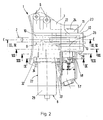
- a convertible top closure 1 serves for securing a convertible top via a movable closure hook 2 to a receptacle 4 arranged on a windscreen frame 3, the convertible top closure 1 having a dimensionally stable front Top frame 5 of the top is connected by screw means which are held in holes 6 of the top closure 1.
- the top closure 1 comprises a fixed to the underside of the front dimensionally rigid top frame 5 base support 7, in its closed position (locking position A) with the windshield frame 3 operatively connected locking hooks 2 and a motor-gear unit 8 for moving the locking hook 2 from the closed position in the Open position (unlocking position B) and vice versa.
- a central, electric motor driven top closure 1 is provided, by means of which the convertible top is pulled in the longitudinal direction of the passenger car against the windshield frame 3 and held in the cocked top position.
- the basic carrier 7 formed, for example, by an aluminum die casting has spaced, extending in the vehicle longitudinal direction and vertically aligned bearing webs 9, 10, 11 for fixing the motor-gear unit 8 and for storage of hook guides 12, 13.
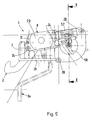
- the closure hook 2 is provided in a front region 14 with a plastic extrusion coating 15, for example made of POM ( Fig. 3 and 4 ).
- a slotted guide 16 is provided for the closure hook 2, wherein a laterally offset clamping pin 17 of the closure hook 2 cooperates with at least one slide track 18 of the base support 7.
- the composite of several juxtaposed web sections slide track 18 is gem. the Fig. 3 and 4 formed by the outer boundary of an arranged on the bearing webs 9, 10 opening 19.
- the entry curves for the front hood section 5 and the front end of the locking hook 2 are in Fig. 4 shown by dashed lines, wherein the inlet curve C the hood section 5 and the inlet curve D are assigned to the locking hook 2.
- the captured between the spaced bearing webs 9, 10 closure hook 2 is pressed by a spring element 20 and a pressure roller 21 from below against the slide track 18.
- the spring element 20 is formed in the embodiment by a double leg spring, which is mounted on a transverse pin of the base support 7. At a transverse overhead end of the double leg spring sits the pressure roller 21, which presses from below against the locking hook 2, whereby the laterally projecting clamping pin 17 is pressed against the slide track 18.
- the rear end of the closure hook 2 cooperates with at least one hook guide 12, 13.
- two differently shaped hook guides 12, 13 are provided for the closure hook 2.
- the motor-gear unit 8 facing away from the hook guide 12 is formed by an elongated drive lever 22 which is connected at its one end via a transverse rivet pin 23 with the rear end of the locking hook 2.
- the other front end of the drive lever 22 is rotatably connected to a hinge pin 24 which is accommodated on the one hand on the central bearing web 10 and on the other hand on the outer bearing web 11.
- the drive lever 22 is placed in the space between the two bearing webs 10, 11.
- the motor gear unit 8 facing hook guide 13 has a disc-shaped contour and is connected via the common rivet pin 23 with the rear end of the locking hook 2 and a polygonal 25 (hexagon) with the transmission output shaft 26 force-transmitting.
- the hook guide 12, 13 is pivoted in the opening and closing operation of the convertible top closure 1 by approximately 160 °, wherein on the base support 7 mechanical stops are formed for both end positions.
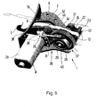
- the motor-gear unit 8 is formed by a prefabricated module 27 which is mounted from one side on an outer bearing web 9 of the base support 7 and secured by a plurality of screws 28 thereto.
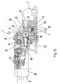
- the motor-gear unit 8 comprises a transverse to the longitudinal center plane E-E of the vehicle aligned electric motor 29, which cooperates via a threefold geared transmission unit 30 with a hook guide 12, 13 for the locking hook 2.
- the motor-gear unit 8 seen in the direction of travel is provided on the left side on the base support 7.
- the electric motor 29 is brought via a rectangular abutment flange 31 to the outside of a multi-part gear housing 32, 33 and fixedly connected by screws 34 ( Fig. 1 ).
- the gear unit 30 is composed of a bevel gear 35, an associated worm gear 36 and a downstream planetary gear 37 together, all gears 35, 36, 37 are housed in the common multi-part gear housing 32, 33.
- the bevel gear 35 comprises a drive bevel gear 39 arranged on an output shaft 38 of the electric motor 29 and a driven bevel gear 41 shrunk on a worm shaft 40, wherein a 90 ° deflection of the force flow takes place by means of the bevel gear set.
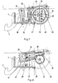
- the output shaft 38 of the electric motor 29 extends approximately at right angles to the longitudinal center plane EE of the vehicle and is oriented approximately horizontally, whereas the worm shaft 40 extends parallel and at a distance from the longitudinal center plane EE. Seen in longitudinal section ( Fig. 8 ), the worm shaft 40 slightly increases toward the rear.
- the worm shaft 40 is supported by two rotationally fixed bearings 42, 43 in the gear housing 32, 33.
- an elongated worm 44 is arranged, which drives an underlying worm wheel 45 of the worm gear 36.
- the worm gear transmits the torque to a sun gear 46 of the planetary gear 37, wherein the sun gear 46 is freely rotatably mounted on the transmission output shaft 26.
- the worm wheel 45 is mounted on the sun gear 46 and rotationally connected thereto.
- the cross to the Vehicle longitudinal center plane EE extending transmission output shaft 26 is mounted at its one end in the transmission housing 32, 33. The opposite end of the transmission output shaft 26 is rotatably mounted on the bearing web 9 of the base support 7.
- the planetary gear 37 comprises, in addition to the sun gear 46, a plurality of planetary gears 48 rotatably mounted on a planet carrier 47 and an outer ring gear 49 (FIG. Fig. 7 ).
- the ring gear 49 has an internal toothing 50 and in addition an external toothing 51.
- the ring gear 49 is held, since the external teeth 51 of the ring gear 49 meshes with a standing arranged emergency operating screw 52.
- the emergency operating screw 52 extends in the space between the driven bevel gear 41 and the ring gear 49.
- the emergency operating screw 52 is mounted in the gear housing 32, 33 and has at its lower, the passenger compartment end facing a polygonal socket 53, in the passenger compartment ago a cranked Notbet2011 institutes negotiatel 54th is pluggable.
- the Notbet2011 tos slaughterl 54 is clipped in the embodiment inside a non-illustrated cover of the base support 7, wherein the cover is placed from the passenger compartment forth on the base support 7.
- the inner sun gear 46 drives the outer planet gears 48, wherein the planetary gears 48 additionally mesh with the internal teeth 50 of the fixed ring gear 49.
- the planet gears 48 are each mounted on transverse needle rollers 55 of the planet carrier 47.
- the planet carrier 47 is seated on a polygonal 56 (eg hexagon) of the transmission output shaft 26. Directly next to the polygon for the planet carrier 47 on the transmission output shaft 26 another polygon 25 (eg hex) for the hook guide 13 is arranged.
- the needle rollers 55 of the planet carrier 47 engage in the hook guide 13 and thereby transmit the torque to the hook guide 13. This is coupled via a polygon with the transmission output shaft 26.
- the transmission output shaft 26 rotates as fast as the hook guide 12, 13.
- the hook guide 12, 13 transmits the force on the locking hook 2 due to a lever arm.
- the shutdown of the electric motor 29 and the query whether the convertible top 1 has reached an end position is realized via a switch assembly 57.
- the switch assembly 57 is seated on the gear housing 32, 33.
- Via a cam plate 58 which is fixed on the rotationally fixed end on the transmission output shaft 26, micro switch for indicating the end position in the switch assembly 57 are driven.
Landscapes
- Engineering & Computer Science (AREA)
- Mechanical Engineering (AREA)
- Lock And Its Accessories (AREA)
- Gear Transmission (AREA)
Claims (7)
- Dispositif (1) de verrouillage de capote pour un véhicule, avec un crochet de verrouillage (2) s'étendant dans la direction longitudinale du véhicule, commandé par coulisse et pouvant être déplacé d'une position fermée dans une position ouverte par l'intermédiaire de moyens de guidage (17, 18), sachant que le crochet de verrouillage (2) coopère avec au moins un guide de crochet (12, 13) qui est fonctionnellement relié à un ensemble moteur-transmission (8) s'étendant sur un seul côté longitudinal du crochet de verrouillage (2), et sachant que la capote est, au moyen du dispositif (1) de verrouillage de capote, tirée dans la direction longitudinale de la voiture particulière contre le cadre de pare-brise (3) et maintenue en position tendue, caractérisé en ce que l'ensemble moteur-transmission (8) comprend un moteur électrique (29) orienté transversalement au plan médian longitudinal (E-E) du véhicule, qui coopère par l'intermédiaire d'un ensemble de transmission (30) à triple démultiplication avec un guide de crochet (12, 13) du crochet de verrouillage (2), en ce que l'ensemble de transmission (30) est composé d'un engrenage conique (35), d'un engrenage (36) à vis sans fin relié au précédent et d'un engrenage planétaire (37) relié en aval, les engrenages (35, 36, 37) étant tous logés dans un boîtier d'engrenages commun (32, 33) en plusieurs parties, et en ce que l'engrenage conique (35) comprend une roue conique menante (39) disposée sur un arbre de sortie (38) du moteur électrique (29) et une roue conique de sortie (41) frettée sur un arbre (40) de vis sans fin, sachant que le jeu de roues coniques (39, 41) effectue un renvoi du flux de force à 90°.
- Dispositif de verrouillage de capote selon la revendication 1, caractérisé en ce que l'arbre (40) de vis sans fin est monté dans le boîtier d'engrenages (32, 33) par l'intermédiaire de deux paliers (42, 43) bloqués en rotation, et en ce qu'une vis sans fin (44), qui entraîne une roue à vis (45) de l'engrenage (36) à vis sans fin, est disposée à l'extrémité de l'arbre (40) de vis sans fin qui est opposée à la roue conique de sortie (41).
- Dispositif de verrouillage de capote selon les revendications 1 et 2, caractérisé en ce que le jeu de roues (44, 45) de l'engrenage (36) à vis sans fin transmet le couple à une roue solaire (46) de l'engrenage planétaire (37) qui est montée librement rotative sur un arbre (26) de sortie de transmission.
- Dispositif de verrouillage de capote selon l'une des revendications précédentes, caractérisé en ce qu'une couronne (49) de l'engrenage planétaire (37) est, pendant le fonctionnement normal du dispositif (1) de verrouillage de capote, immobilisée par une vis sans fin (52) d'actionnement de secours.
- Dispositif de verrouillage de capote selon l'une des revendications précédentes, caractérisé en ce que la sortie de l'engrenage planétaire (37) s'effectue par l'intermédiaire d'un porte-satellites (47) qui transmet le couple directement sur le guide de crochet (12, 13).
- Dispositif de verrouillage de capote selon l'une des revendications précédentes, caractérisé en ce que le guide de crochet (12, 13) est relié à un arbre (26) de sortie de transmission par l'intermédiaire d'un multipans.
- Dispositif de verrouillage de capote selon l'une des revendications précédentes, caractérisé en ce que le crochet de verrouillage (2) commandé par coulisse est pressé par en dessous contre une coulisse (18) par l'intermédiaire d'un ressort (20) à double branche et d'un galet de pression (21).
Applications Claiming Priority (1)
| Application Number | Priority Date | Filing Date | Title |
|---|---|---|---|
| DE200410046098 DE102004046098A1 (de) | 2004-09-23 | 2004-09-23 | Verdeckverschluss für ein Fahrzeug |
Publications (2)
| Publication Number | Publication Date |
|---|---|
| EP1640200A1 EP1640200A1 (fr) | 2006-03-29 |
| EP1640200B1 true EP1640200B1 (fr) | 2008-03-12 |
Family
ID=34937839
Family Applications (1)
| Application Number | Title | Priority Date | Filing Date |
|---|---|---|---|
| EP20050015181 Expired - Lifetime EP1640200B1 (fr) | 2004-09-23 | 2005-07-13 | Dispositif de verrouillage pour toit de véhicule |
Country Status (3)
| Country | Link |
|---|---|
| US (1) | US7407201B2 (fr) |
| EP (1) | EP1640200B1 (fr) |
| DE (2) | DE102004046098A1 (fr) |
Cited By (3)
| Publication number | Priority date | Publication date | Assignee | Title |
|---|---|---|---|---|
| DE102010044702A1 (de) | 2010-09-08 | 2012-03-08 | Magna Car Top Systems Gmbh | Verschlusseinrichtung |
| DE102010044700A1 (de) | 2010-09-08 | 2012-03-08 | Magna Car Top Systems Gmbh | Verschlusseinrichtung |
| DE102010044704A1 (de) | 2010-09-08 | 2012-03-08 | Magna Car Top Systems Gmbh | Verschlusseinrichtung |
Families Citing this family (14)
| Publication number | Priority date | Publication date | Assignee | Title |
|---|---|---|---|---|
| DE10357100B4 (de) * | 2003-12-06 | 2005-10-20 | Karmann Gmbh W | Cabriolet-Fahrzeug |
| DE102004044908B3 (de) * | 2004-09-14 | 2006-06-14 | Wilhelm Karmann Gmbh | Cabriolet-Fahrzeug |
| DE102007021083A1 (de) * | 2007-05-03 | 2008-11-06 | Webasto Ag | Verriegelungsvorrichtung für eine Dachabdeckung bei einem Fahrzeug |
| DE102008003880B4 (de) * | 2008-01-10 | 2013-05-29 | Magna Car Top Systems Gmbh | Verschluss für ein bewegliches Dach |
| DE102010014490A1 (de) | 2010-04-10 | 2011-10-13 | Magna Car Top Systems Gmbh | Antriebsgetriebe für einen Verdeckverschluss |
| DE102010035286A1 (de) | 2010-08-25 | 2012-03-01 | Magna Car Top Systems Gmbh | Verstellantrieb mit Notbetätigung |
| KR101199146B1 (ko) | 2010-12-06 | 2012-11-12 | 현대자동차주식회사 | 오픈카용 루프장치 |
| US9221378B2 (en) * | 2012-11-20 | 2015-12-29 | AL-KO Kober A.G. | Slide-out room mechanism for a vehicle |
| DE102015120267B4 (de) * | 2015-11-23 | 2022-04-28 | Webasto-Edscha Cabrio GmbH | Verschlussvorrichtung mit Verschlusshaken |
| JP6595939B2 (ja) * | 2016-03-18 | 2019-10-23 | ベバスト ジャパン株式会社 | ルーフロック装置 |
| JP6197902B2 (ja) * | 2016-03-18 | 2017-09-20 | マツダ株式会社 | 自動車の開閉体ロック構造 |
| JP6726494B2 (ja) * | 2016-03-18 | 2020-07-22 | マツダ株式会社 | 自動車の開閉体ロック構造、及び自動車の開閉体ロック方法 |
| DE102016124451B4 (de) * | 2016-12-15 | 2023-12-21 | Webasto-Edscha Cabrio GmbH | Verschlussvorrichtung mit Verschlusshaken und verfahrbarem Schlitten |
| DE102018110634B4 (de) * | 2018-05-03 | 2025-03-20 | Webasto SE | Verschlussvorrichtung mit Lenkeranordnung und Schlitten |
Family Cites Families (15)
| Publication number | Priority date | Publication date | Assignee | Title |
|---|---|---|---|---|
| SE448701B (sv) * | 1983-12-17 | 1987-03-16 | Webasto Werk Baier Kg W | Anordning for styrning av skjutrorelsen och uppfellningsrorelsen hos luckan vid med taklucka forsedda fordon |
| US4709950A (en) * | 1984-06-21 | 1987-12-01 | American Device Manufacturing Co. | Crash bar door locking device |
| US4796932A (en) * | 1987-09-22 | 1989-01-10 | Hoover Universal, Inc. | Remote release and pull-down unit |
| US5058939A (en) * | 1990-11-28 | 1991-10-22 | Asc Incorporated | Power latch system |
| GB9418895D0 (en) * | 1994-09-20 | 1994-11-09 | Lucas Ind Plc | Lock mechanism |
| US5772274A (en) * | 1995-01-31 | 1998-06-30 | Asc Incorporated | Motorized drive system for a convertible roof of an automotive vehicle |
| DE19721229B4 (de) * | 1997-05-21 | 2005-05-04 | Dr.Ing.H.C. F. Porsche Ag | Verschluß für ein Verdeck eines Fahrzeuges, insbesondere eines Personenkraftwagens |
| JPH11334379A (ja) * | 1998-05-27 | 1999-12-07 | Asmo Co Ltd | アクチュエータ |
| DE10000002C2 (de) * | 2000-01-01 | 2002-06-27 | Webasto Vehicle Sys Int Gmbh | Verriegelungsvorrichtung für ein Klappverdeck |
| US6550825B2 (en) * | 2000-06-06 | 2003-04-22 | Delphi Technologies, Inc. | Cinching door latch with planetary release mechanism |
| JP4617582B2 (ja) * | 2001-02-23 | 2011-01-26 | アイシン精機株式会社 | 車両用ドア操作装置の駆動用モータ装置及び車両用ドアクローザ装置 |
| FR2835870B1 (fr) * | 2002-02-14 | 2005-03-11 | Airbus France | Systeme de fermeture interpose entre deux elements |
| DE10300883B3 (de) * | 2003-01-13 | 2004-03-11 | Dr.Ing.H.C. F. Porsche Ag | Abdeckung für einen Verschluß eines Verdecks |
| DE10300882B4 (de) * | 2003-01-13 | 2005-07-21 | Dr.Ing.H.C. F. Porsche Ag | Verdeckverschluss eines Fahrzeugs |
| DE10300881A1 (de) * | 2003-01-13 | 2004-07-29 | Gross, Beatrix | Antriebseinheit zur Bewegung von Komponenten eines Kraftfahrzeugs |
-
2004
- 2004-09-23 DE DE200410046098 patent/DE102004046098A1/de not_active Withdrawn
-
2005
- 2005-07-13 EP EP20050015181 patent/EP1640200B1/fr not_active Expired - Lifetime
- 2005-07-13 DE DE200550003177 patent/DE502005003177D1/de not_active Expired - Lifetime
- 2005-08-15 US US11/203,114 patent/US7407201B2/en not_active Expired - Lifetime
Cited By (8)
| Publication number | Priority date | Publication date | Assignee | Title |
|---|---|---|---|---|
| DE102010044702A1 (de) | 2010-09-08 | 2012-03-08 | Magna Car Top Systems Gmbh | Verschlusseinrichtung |
| DE102010044700A1 (de) | 2010-09-08 | 2012-03-08 | Magna Car Top Systems Gmbh | Verschlusseinrichtung |
| DE102010044704A1 (de) | 2010-09-08 | 2012-03-08 | Magna Car Top Systems Gmbh | Verschlusseinrichtung |
| EP2428379A1 (fr) | 2010-09-08 | 2012-03-14 | Magna Car Top Systems GmbH | Dispositif de verrouillage |
| EP2428381A2 (fr) | 2010-09-08 | 2012-03-14 | Magna Car Top Systems GmbH | Dispositif de verrouillage |
| EP2428380A2 (fr) | 2010-09-08 | 2012-03-14 | Magna Car Top Systems GmbH | Dispositif de verrouillage |
| DE102010044700B4 (de) * | 2010-09-08 | 2015-07-09 | Magna Car Top Systems Gmbh | Verschlusseinrichtung |
| DE102010044704B4 (de) * | 2010-09-08 | 2015-07-16 | Magna Car Top Systems Gmbh | Verschlusseinrichtung |
Also Published As
| Publication number | Publication date |
|---|---|
| DE102004046098A1 (de) | 2006-04-06 |
| US20060061109A1 (en) | 2006-03-23 |
| EP1640200A1 (fr) | 2006-03-29 |
| US7407201B2 (en) | 2008-08-05 |
| DE502005003177D1 (de) | 2008-04-24 |
Similar Documents
| Publication | Publication Date | Title |
|---|---|---|
| EP1640200B1 (fr) | Dispositif de verrouillage pour toit de véhicule | |
| EP0760304B1 (fr) | Capote pour véhicule, en particulier pour véhicule automobile | |
| EP2065260B1 (fr) | Dispositif de protection de bordure de portière | |
| EP2423022B1 (fr) | Mécanisme d'entraînement muni d'un actionnement d'urgence | |
| EP1101886A2 (fr) | Serrure de porte pour véhicule automobile | |
| DE102006025383B3 (de) | Bordmonitoreinrichtung | |
| WO2015024555A1 (fr) | Fermeture pour portière de véhicule automobile | |
| EP0837209A2 (fr) | Porte pivotante et coulissante pour véhicules | |
| DE3420016C2 (fr) | ||
| DE19721229A1 (de) | Verschluß für ein Verdeck eines Fahrzeuges, insbesondere eines Personenkraftwagens | |
| DE102008003880B4 (de) | Verschluss für ein bewegliches Dach | |
| EP2428380B1 (fr) | Dispositif de verrouillage | |
| EP1767388A2 (fr) | Porte pivotante-coulissante pour véhicules de transport de personnes | |
| DE202005015166U1 (de) | Schwenkschiebetür für Fahrzeuge, insbesondere Fahrgasttür für Fahrzeuge des öffentlichen Personennahverkehrs | |
| WO2022084146A1 (fr) | Entraînement de portière pour système de portière coulissante de véhicule | |
| EP2223817B1 (fr) | Dispositif de fermeture pour un toit du type cabriolet | |
| DE19702083C1 (de) | Türsystem, insbesondere für ein Passagierflugzeug | |
| EP3805496B1 (fr) | Verrouillage à pênes pivotants pour un système de porte | |
| DE4101288A1 (de) | Spoilerdach fuer fahrzeuge | |
| DE102007024570B4 (de) | Scharnier für eine Kraftfahrzeugtür | |
| DE3878644T2 (de) | Schiebedach fuer ein kraftfahrzeug. | |
| AT408735B (de) | Betätigungsanordnung für schwenkbare teile an fahrzeugen | |
| EP1200287B1 (fr) | Retroviseur escamotable de vehicules automobiles | |
| DE202022002146U1 (de) | Schwenkschiebetür für ein Fahrzeug | |
| EP1707415B1 (fr) | Cabriolet avec actionneur d'urgence manuel |
Legal Events
| Date | Code | Title | Description |
|---|---|---|---|
| PUAI | Public reference made under article 153(3) epc to a published international application that has entered the european phase |
Free format text: ORIGINAL CODE: 0009012 |
|
| AK | Designated contracting states |
Kind code of ref document: A1 Designated state(s): AT BE BG CH CY CZ DE DK EE ES FI FR GB GR HU IE IS IT LI LT LU LV MC NL PL PT RO SE SI SK TR |
|
| AX | Request for extension of the european patent |
Extension state: AL BA HR MK YU |
|
| 17P | Request for examination filed |
Effective date: 20060929 |
|
| 17Q | First examination report despatched |
Effective date: 20061102 |
|
| AKX | Designation fees paid |
Designated state(s): DE ES FR GB IT |
|
| GRAP | Despatch of communication of intention to grant a patent |
Free format text: ORIGINAL CODE: EPIDOSNIGR1 |
|
| GRAS | Grant fee paid |
Free format text: ORIGINAL CODE: EPIDOSNIGR3 |
|
| GRAA | (expected) grant |
Free format text: ORIGINAL CODE: 0009210 |
|
| RIN1 | Information on inventor provided before grant (corrected) |
Inventor name: RANFT, DETLEV Inventor name: POPP, HARTMUT Inventor name: PFERTNER, KURT |
|
| AK | Designated contracting states |
Kind code of ref document: B1 Designated state(s): DE ES FR GB IT |
|
| REG | Reference to a national code |
Ref country code: GB Ref legal event code: FG4D Free format text: NOT ENGLISH |
|
| REF | Corresponds to: |
Ref document number: 502005003177 Country of ref document: DE Date of ref document: 20080424 Kind code of ref document: P |
|
| RAP2 | Party data changed (patent owner data changed or rights of a patent transferred) |
Owner name: DR. ING. H.C. F. PORSCHE AKTIENGESELLSCHAFT |
|
| RAP2 | Party data changed (patent owner data changed or rights of a patent transferred) |
Owner name: DR. ING. H.C. F. PORSCHE AKTIENGESELLSCHAFT |
|
| ET | Fr: translation filed | ||
| PG25 | Lapsed in a contracting state [announced via postgrant information from national office to epo] |
Ref country code: ES Free format text: LAPSE BECAUSE OF FAILURE TO SUBMIT A TRANSLATION OF THE DESCRIPTION OR TO PAY THE FEE WITHIN THE PRESCRIBED TIME-LIMIT Effective date: 20080623 |
|
| PLBE | No opposition filed within time limit |
Free format text: ORIGINAL CODE: 0009261 |
|
| STAA | Information on the status of an ep patent application or granted ep patent |
Free format text: STATUS: NO OPPOSITION FILED WITHIN TIME LIMIT |
|
| 26N | No opposition filed |
Effective date: 20081215 |
|
| REG | Reference to a national code |
Ref country code: FR Ref legal event code: TP |
|
| REG | Reference to a national code |
Ref country code: FR Ref legal event code: CD |
|
| PGFP | Annual fee paid to national office [announced via postgrant information from national office to epo] |
Ref country code: FR Payment date: 20100805 Year of fee payment: 6 Ref country code: IT Payment date: 20100722 Year of fee payment: 6 |
|
| PGFP | Annual fee paid to national office [announced via postgrant information from national office to epo] |
Ref country code: GB Payment date: 20100722 Year of fee payment: 6 |
|
| REG | Reference to a national code |
Ref country code: FR Ref legal event code: TP |
|
| REG | Reference to a national code |
Ref country code: GB Ref legal event code: 732E Free format text: REGISTERED BETWEEN 20110310 AND 20110316 |
|
| REG | Reference to a national code |
Ref country code: GB Ref legal event code: 732E Free format text: REGISTERED BETWEEN 20110331 AND 20110406 |
|
| GBPC | Gb: european patent ceased through non-payment of renewal fee |
Effective date: 20110713 |
|
| REG | Reference to a national code |
Ref country code: FR Ref legal event code: ST Effective date: 20120330 |
|
| PG25 | Lapsed in a contracting state [announced via postgrant information from national office to epo] |
Ref country code: FR Free format text: LAPSE BECAUSE OF NON-PAYMENT OF DUE FEES Effective date: 20110801 |
|
| PG25 | Lapsed in a contracting state [announced via postgrant information from national office to epo] |
Ref country code: IT Free format text: LAPSE BECAUSE OF NON-PAYMENT OF DUE FEES Effective date: 20110713 |
|
| PG25 | Lapsed in a contracting state [announced via postgrant information from national office to epo] |
Ref country code: GB Free format text: LAPSE BECAUSE OF NON-PAYMENT OF DUE FEES Effective date: 20110713 |
|
| PGFP | Annual fee paid to national office [announced via postgrant information from national office to epo] |
Ref country code: DE Payment date: 20190704 Year of fee payment: 15 |
|
| REG | Reference to a national code |
Ref country code: DE Ref legal event code: R119 Ref document number: 502005003177 Country of ref document: DE |
|
| PG25 | Lapsed in a contracting state [announced via postgrant information from national office to epo] |
Ref country code: DE Free format text: LAPSE BECAUSE OF NON-PAYMENT OF DUE FEES Effective date: 20210202 |