EP1640645B1 - Dispositif d'étanchéité pour arbre - Google Patents
Dispositif d'étanchéité pour arbre Download PDFInfo
- Publication number
- EP1640645B1 EP1640645B1 EP05028506A EP05028506A EP1640645B1 EP 1640645 B1 EP1640645 B1 EP 1640645B1 EP 05028506 A EP05028506 A EP 05028506A EP 05028506 A EP05028506 A EP 05028506A EP 1640645 B1 EP1640645 B1 EP 1640645B1
- Authority
- EP
- European Patent Office
- Prior art keywords
- shaft
- sealing
- annular
- driving shaft
- cylindrical surface
- Prior art date
- Legal status (The legal status is an assumption and is not a legal conclusion. Google has not performed a legal analysis and makes no representation as to the accuracy of the status listed.)
- Expired - Lifetime
Links
Images


Classifications
-
- F—MECHANICAL ENGINEERING; LIGHTING; HEATING; WEAPONS; BLASTING
- F16—ENGINEERING ELEMENTS AND UNITS; GENERAL MEASURES FOR PRODUCING AND MAINTAINING EFFECTIVE FUNCTIONING OF MACHINES OR INSTALLATIONS; THERMAL INSULATION IN GENERAL
- F16J—PISTONS; CYLINDERS; SEALINGS
- F16J15/00—Sealings
-
- F—MECHANICAL ENGINEERING; LIGHTING; HEATING; WEAPONS; BLASTING
- F16—ENGINEERING ELEMENTS AND UNITS; GENERAL MEASURES FOR PRODUCING AND MAINTAINING EFFECTIVE FUNCTIONING OF MACHINES OR INSTALLATIONS; THERMAL INSULATION IN GENERAL
- F16J—PISTONS; CYLINDERS; SEALINGS
- F16J15/00—Sealings
- F16J15/16—Sealings between relatively-moving surfaces
- F16J15/32—Sealings between relatively-moving surfaces with elastic sealings, e.g. O-rings
- F16J15/324—Arrangements for lubrication or cooling of the sealing itself
-
- F—MECHANICAL ENGINEERING; LIGHTING; HEATING; WEAPONS; BLASTING
- F16—ENGINEERING ELEMENTS AND UNITS; GENERAL MEASURES FOR PRODUCING AND MAINTAINING EFFECTIVE FUNCTIONING OF MACHINES OR INSTALLATIONS; THERMAL INSULATION IN GENERAL
- F16J—PISTONS; CYLINDERS; SEALINGS
- F16J15/00—Sealings
- F16J15/002—Sealings comprising at least two sealings in succession
- F16J15/006—Sealings comprising at least two sealings in succession with division of the pressure
-
- F—MECHANICAL ENGINEERING; LIGHTING; HEATING; WEAPONS; BLASTING
- F16—ENGINEERING ELEMENTS AND UNITS; GENERAL MEASURES FOR PRODUCING AND MAINTAINING EFFECTIVE FUNCTIONING OF MACHINES OR INSTALLATIONS; THERMAL INSULATION IN GENERAL
- F16J—PISTONS; CYLINDERS; SEALINGS
- F16J15/00—Sealings
- F16J15/16—Sealings between relatively-moving surfaces
- F16J15/32—Sealings between relatively-moving surfaces with elastic sealings, e.g. O-rings
- F16J15/3204—Sealings between relatively-moving surfaces with elastic sealings, e.g. O-rings with at least one lip
- F16J15/3208—Sealings between relatively-moving surfaces with elastic sealings, e.g. O-rings with at least one lip provided with tension elements, e.g. elastic rings
- F16J15/3212—Sealings between relatively-moving surfaces with elastic sealings, e.g. O-rings with at least one lip provided with tension elements, e.g. elastic rings with metal springs
-
- F—MECHANICAL ENGINEERING; LIGHTING; HEATING; WEAPONS; BLASTING
- F16—ENGINEERING ELEMENTS AND UNITS; GENERAL MEASURES FOR PRODUCING AND MAINTAINING EFFECTIVE FUNCTIONING OF MACHINES OR INSTALLATIONS; THERMAL INSULATION IN GENERAL
- F16J—PISTONS; CYLINDERS; SEALINGS
- F16J15/00—Sealings
- F16J15/16—Sealings between relatively-moving surfaces
- F16J15/32—Sealings between relatively-moving surfaces with elastic sealings, e.g. O-rings
- F16J15/3204—Sealings between relatively-moving surfaces with elastic sealings, e.g. O-rings with at least one lip
- F16J15/3232—Sealings between relatively-moving surfaces with elastic sealings, e.g. O-rings with at least one lip having two or more lips
- F16J15/3236—Sealings between relatively-moving surfaces with elastic sealings, e.g. O-rings with at least one lip having two or more lips with at least one lip for each surface, e.g. U-cup packings
-
- F—MECHANICAL ENGINEERING; LIGHTING; HEATING; WEAPONS; BLASTING
- F16—ENGINEERING ELEMENTS AND UNITS; GENERAL MEASURES FOR PRODUCING AND MAINTAINING EFFECTIVE FUNCTIONING OF MACHINES OR INSTALLATIONS; THERMAL INSULATION IN GENERAL
- F16J—PISTONS; CYLINDERS; SEALINGS
- F16J15/00—Sealings
- F16J15/54—Other sealings for rotating shafts
-
- H—ELECTRICITY
- H10—SEMICONDUCTOR DEVICES; ELECTRIC SOLID-STATE DEVICES NOT OTHERWISE PROVIDED FOR
- H10P—GENERIC PROCESSES OR APPARATUS FOR THE MANUFACTURE OR TREATMENT OF DEVICES COVERED BY CLASS H10
- H10P72/00—Handling or holding of wafers, substrates or devices during manufacture or treatment thereof
- H10P72/70—Handling or holding of wafers, substrates or devices during manufacture or treatment thereof for supporting or gripping
- H10P72/76—Handling or holding of wafers, substrates or devices during manufacture or treatment thereof for supporting or gripping using mechanical means, e.g. clamps or pinches
- H10P72/7604—Handling or holding of wafers, substrates or devices during manufacture or treatment thereof for supporting or gripping using mechanical means, e.g. clamps or pinches the wafers being placed on a susceptor, stage or support
- H10P72/7626—Handling or holding of wafers, substrates or devices during manufacture or treatment thereof for supporting or gripping using mechanical means, e.g. clamps or pinches the wafers being placed on a susceptor, stage or support characterised by the construction of the shaft
-
- Y—GENERAL TAGGING OF NEW TECHNOLOGICAL DEVELOPMENTS; GENERAL TAGGING OF CROSS-SECTIONAL TECHNOLOGIES SPANNING OVER SEVERAL SECTIONS OF THE IPC; TECHNICAL SUBJECTS COVERED BY FORMER USPC CROSS-REFERENCE ART COLLECTIONS [XRACs] AND DIGESTS
- Y10—TECHNICAL SUBJECTS COVERED BY FORMER USPC
- Y10S—TECHNICAL SUBJECTS COVERED BY FORMER USPC CROSS-REFERENCE ART COLLECTIONS [XRACs] AND DIGESTS
- Y10S277/00—Seal for a joint or juncture
- Y10S277/913—Seal for fluid pressure below atmospheric, e.g. vacuum
Definitions
- the present invention relates to a shaft sealing apparatus, and more particularly to a shaft sealing apparatus for sealing the gaps between a driving shaft and other parts around the driving shaft to have the driving shaft movably extending in a vacuum chamber and operatively connected with a handling mechanism disposed in the vacuum chamber.
- EP-A-266 732 discloses a kind of shaft sealing apparatus, which comprises a cylindrical hollow seal housing, a stirrer shaft rotatably supported in the seal housing through a rolling contact bearing, a casing having the seal housing partly received therein, a plurality of sealing lips intervening between the rotation shaft and the seal housing to hermetically seal the gap between the rotation shaft and the seal housing, a set of spacer discs and bracing discs respectively axially spaced to one another in the gap between the rotation shaft and the seal housing so as to have the sealing lips peripherally guided and braced against the rolling contact bearing.
- the vacuum processing apparatus of this type is equipped with a vacuum casing formed with a vacuum chamber and a handling mechanism such as a manipulator designed to handle wafers and other substrates in the vacuum chamber.
- the vacuum processing apparatus thus constructed is operative to produce various precision products including an integrated circuit (IC), a large scale integrated circuit (LSI) and a liquid crystal display (LCD) base plate.
- IC integrated circuit
- LSI large scale integrated circuit
- LCD liquid crystal display
- the precision products produced by the vacuum processing apparatus are used for a semiconductor device, a liquid crystal display (LCD) and other objects.
- the precision products described in the above are produced in the vacuum chamber maintained at a constant vacuum level, for example, a high vacuum level (1 ⁇ 10 -1 to 1 ⁇ 10 -5 Pa) and an ultra high vacuum level (less than 1 ⁇ 10 -5 Pa), resulting from the fact that the process of producing the precision products has been progressed to obtain more excellent quality and to reduce inferior products.
- the conventional shaft sealing apparatus is, therefore, installed in the vacuum processing apparatus to have the vacuum chamber maintained at a constant vacuum level.
- the conventional shaft sealing apparatus of this type comprises a vacuum casing formed with a vacuum chamber and an opening to have the vacuum chamber held in communication with the atmosphere through the opening, a shaft housing fixedly connected with the vacuum casing, and a driving shaft received in the shaft housing to be rotatably supported by the shaft housing.
- the driving shaft has a first axial end extending in the vacuum chamber to be operatively connected with the handling mechanism disposed in the vacuum chamber, and a second axial end extending in the atmosphere to be operatively connected with an electric motor.
- the handling mechanism includes a handling member pivotally supported by the driving shaft to be operative to handle wafers and other substrates in the vacuum chamber.
- a shaft sealing apparatus which comprises a vacuum casing formed with a vacuum chamber, an opening, a shaft housing fixedly connected with the vacuum casing, a driving shaft rotatably received in the shaft housing, a plurality of sealing rings intervening between the driving shaft and the shaft housing to seal the gap between the driving shaft and the shaft housing, and air sucking means having for maintaining the pressure of the gap between adjacent two of the sealing rings at a level between the atmospheric pressure and the inner pressure of the vacuum chamber.
- the seating rings are prevented from moving toward the vacuum chamber by a plurality of stop rings each held in contact with the inner cylindrical surface of the support member and the outer cylindrical surface of the driving shaft.
- Another conventional shaft sealing apparatus of this type comprises a plurality of magnetic fluid seals intervening between the driving shaft and the shaft housing to hermetically seal the gap between the driving shaft and the shaft housing.
- the magnetic fluid seals are axially disposed in series between the driving shaft and the shaft housing, resulting from the fact that each of the magnetic fluid seals has a resistance pressure of approximately 20 kPa.
- the conventional shaft sealing apparatus described in the above encounters another problem that the conventional shaft sealing apparatus is difficult to assemble, resulting from the fact that the conventional shaft sealing apparatus is complicated in construction and thus large in size.
- the conventional shaft sealing apparatus including the magnetic fluid seals encounters further problem that the driving shaft cannot be axially movably supported by the shaft housing, resulting from the fact that the magnetic fluid seals intervene between the driving shaft and the shaft housing.
- the conventional shaft sealing apparatus comprises a driving shaft movably extending in the vacuum chamber
- the driving shaft may be replaced by a driving shaft accommodated in a vacuum chamber in order to have the vacuum chamber maintained at a constant vacuum level.
- This type of shaft sealing apparatus is disclosed in Japanese Patent Publication No. 2761438 B2 (family member of WO 9423911 ).
- the conventional shaft sealing apparatus of this type comprises a vacuum casing formed with a casing chamber and an opening, a shaft housing formed with a housing chamber and axially movably connected with the vacuum casing through a bellows unit, and a driving shaft received in the shaft housing to be rotatably supported by the shaft housing.
- the casing chamber is held in communication with the housing chamber through the opening to ensure that the casing chamber and the housing chamber collectively define a vacuum chamber.
- the driving shaft is accommodated in the vacuum chamber to be operatively connected at one end with the handling mechanism disposed in the casing chamber and at the other end with an electric motor disposed in the housing chamber.
- the handling mechanism includes a handling member pivotally supported by the driving shaft to be operative to handle wafers and other substrates in the casing chamber.
- the conventional shaft sealing apparatus thus constructed, however, encounters such a problem that the conventional shaft sealing apparatus is complicated in construction and thus increased in size, resulting from the fact that the conventional shaft sealing apparatus is required to comprise a shaft housing axially movably connected with the vacuum casing through the bellows unit.
- the conventional shaft sealing apparatus described in the above encounters another problem that the exhaust load of the vacuum chamber is increased, resulting from the fact that the vacuum chamber is increased in space to have the driving shaft, the electric motor and other parts accommodated in the vacuum chamber.
- the conventional shaft sealing apparatus described in the above encounters further problem that dust particles generated from the driving shaft, the electric motor and other parts are discharged into the vacuum chamber, resulting from the fact that the driving shaft, the electric motor and other parts are accommodated in the vacuum chamber.
- an object of the present invention to provide a shaft sealing apparatus that is excellent in characteristic to seal the gaps between a driving shaft and other parts around the driving shaft.
- the above shaft sealing apparatus may comprise a cylindrical hollow member having the driving shaft rotatably supported therein.
- the annular spring member of the sealing ring may be made of a metal wire in the form of a helical shape and is of a circular cross-section taken on the plane perpendicular to the center axis passing therethrough.
- the annular spring member of the sealing ring may be made of a metal plate in the form of an annular ring shape and is of a channel-shaped cross-section taken on the plane perpendicular to the center axis passing therethrough.
- the sealing lip of the sealing ring may be made of a synthetic resin constituted by an ultra high molecular weight compound.
- the vacuum casing may have a base portion formed with the opening to have the vacuum chamber of the vacuum casing held in communication with the atmosphere through the opening of the vacuum casing.
- the apparatus may further comprise a shaft housing in the form of a cylindrical hollow shape and fixedly connected with the base portion of the vacuum casing, the shaft housing having an inner cylindrical surface; a driving shaft in the form of a cylindrical shape and received in the shaft housing to be movably supported by the shaft housing, the driving shaft held in coaxial alignment with the shaft housing and having a first axial end extending in the vacuum chamber of the vacuum casing, and a second axial end extending in the atmosphere, and an outer cylindrical surface smaller in diameter than the inner cylindrical surface of the shaft housing.
- the sealing unit may include an annular resilient member formed with an annular groove, and an annular spring member received in the annular groove of the annular resilient member and retained by the annular resilient member, the annular resilient member of the sealing ring having a peripheral portion securely retained by the retaining member, and a sealing lip integrally formed with the peripheral portion of the annular resilient member and radially inwardly extending from the peripheral portion of the annular resilient member to be held in contact with the outer cylindrical surface of the driving shaft, the annular spring member of the sealing ring operative to impart a force to the sealing lip of the annular resilient member to ensure that the sealing lip of the annular resilient member is held in tight contact with the outer cylindrical surface of the driving shaft.
- the driving shaft may be a sleeve shaft in the form of a cylindrical hollow shape and movably received in the shaft housing to be held in coaxial alignment with the shaft housing.
- the apparatus may further comprise a center shaft in the form of a cylindrical shape and movably received in the sleeve shaft, the center shaft held in coaxial alignment with the sleeve shaft and having a first axial end extending in the vacuum chamber of the vacuum casing, a second axial end extending in the atmosphere, and an outer cylindrical surface smaller in diameter than the inner cylindrical surface of the sleeve shaft; an additional sealing unit provided on the first axial end of the sleeve shaft and held in coaxial alignment with the sleeve shaft, the additional sealing unit including a retaining member in the form of an annular ring shape and fixedly connected with the first axial end of the sleeve shaft, and a sealing ring in the form of an annular ring shape and securely retained by the retaining member of the additional
- the shaft sealing apparatus may further comprise a first labyrinth seal unit intervening between the sleeve shaft and the center shaft to be exposed to the vacuum chamber of the vacuum casing, and a second labyrinth seal unit intervening between the vacuum casing and the sleeve shaft to be exposed to the vacuum chamber of the vacuum casing, the first labyrinth seal unit including an outer ring member provided on the first axial end of the sleeve shaft, and an inner ring member provided on the first axial end of the center shaft, the outer and inner ring members of the first labyrinth seal unit collectively forming an interstice therebetween, the second labyrinth seal unit including an outer ring member provided on the base portion of the vacuum casing, and an inner ring member provided on the first axial end of the sleeve shaft, the outer and inner ring members of the second labyrinth seal unit collectively forming an interstice therebetween.
- the shaft sealing apparatus may further comprise a base member in the form of a circular shape and provided on the first axial end of the center shaft, a first fixed member in the form of an annular ring shape and provided on the first axial end of the sleeve shaft, and a second fixed member in the form of an annular ring shape and provided on the base portion of the vacuum casing, the base member and the first fixed member collectively constituting the first labyrinth seal unit, the first and second fixed members collectively constituting the second labyrinth seal unit.
- the shaft sealing apparatus 100 is available for a vacuum processing apparatus equipped with a handling mechanism.
- the shaft sealing apparatus 100 comprises a vacuum casing 110 formed with a vacuum chamber 111, and a shaft housing 120 in the form of a cylindrical hollow shape and fixedly connected with the vacuum casing 110.
- the vacuum casing 110 has a base portion 110a formed with an opening 110b to have the vacuum chamber 111 of the vacuum casing 110 held in communication with the atmosphere 112 through the opening 110b of the vacuum casing 110.
- the shaft housing 120 is fixedly connected with the base portion 110a of the vacuum casing 110 by bolts 121.
- the shaft housing 120 has an inner cylindrical surface 120a.
- the shaft sealing apparatus 100 further comprises a sleeve shaft 130 in the form of a cylindrical hollow shape and received in the shaft housing 120 to be movably supported by the shaft housing 120.
- the sleeve shaft 130 is held in coaxial alignment with the shaft housing 120 and rotatable around its own axis with respect to the shaft housing 120.
- the sleeve shaft 130 has a first axial end 130a extending in the vacuum chamber 111 of the vacuum casing 110, a second axial end, not shown, extending in the atmosphere 112, an outer cylindrical surface 130b smaller in diameter than the inner cylindrical surface 120a of the shaft housing 120, and an inner cylindrical surface 130c.
- the sleeve shaft 130 constitutes a driving shaft having an outer cylindrical surface and movably extending in the vacuum chamber 111 of the vacuum casing 112.
- shaft sealing apparatus 100 has been described in the above as comprising a sleeve shaft 130 rotatable around its own axis with respect to the shaft housing 120, the sleeve shaft 130 may be replaced by a sleeve shaft axially movable along its own axis with respect to said shaft housing 120 according to the present invention.
- the shaft sealing apparatus 100 has been described in the above as comprising a sleeve shaft 130 in the form of a cylindrical hollow shape and received in the shaft housing 120 to be held in coaxial alignment with the shaft housing 120, the sleeve shaft 130 may be replaced by a plurality of sleeve shafts each in the form of a cylindrical hollow shape and received in the shaft housing 120 to be held in coaxial alignment with the shaft housing 120 according to the present invention.
- the shaft sealing apparatus 100 further comprises a center shaft 140 in the form of a cylindrical shape and received in the sleeve shaft 130 to be movably supported by the sleeve shaft 130.
- the center shaft 140 is held in coaxial alignment with the sleeve shaft 130 and rotatable around its own axis with respect to the sleeve shaft 130.
- the center shaft 140 has a first axial end 140a extending in the vacuum chamber 111 of the vacuum casing 110, a second axial end, not shown, extending in the atmosphere 112, and an outer cylindrical surface 140b smaller in diameter than the inner cylindrical surface 130c of the sleeve shaft 130.
- the center shaft 140 constitutes a driving shaft having an outer cylindrical surface and movably extending in the vacuum chamber 111 of the vacuum casing 112. ) While the shaft sealing apparatus 100 has been described in the above as comprising a center shaft 140 rotatable around its own axis with respect to the sleeve shaft 130, the center shaft 140 may be replaced by a center shaft axially movable along its own axis with respect to said sleeve shaft 130 according to the present invention.
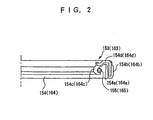
- the shaft sealing apparatus 100 further comprises a first sealing unit 150 provided on the first axial end 130a of the sleeve shaft 130 and held in axial alignment with the sleeve shaft 130.
- the first sealing unit 150 includes a retaining member 151 in the form of an annular ring shape and fixedly connected with the first axial end 130a of the sleeve shaft 130 by bolts 152, and a plurality of sealing rings 153 securely retained by the retaining member 151 of the first sealing unit 150 to be held in axial alignment with each other.
- Each of the sealing rings 153 of the first sealing unit 150 is in the form of an annular ring shape and intervenes between the center shaft 140 and the retaining member 151 of the first sealing unit 150 to hermetically seal the gap between the center shaft 140 and the retaining member 151 of the first sealing unit 150.
- the sealing rings 153 of the first sealing unit 150 are held in contact with each other.
- the retaining member 151 of the first sealing unit 150 has a first axial end 151a extending in the vacuum chamber 111 of the vacuum casing 110, a second axial end 151b held in contact with the first axial end 130a of the sleeve shaft 130, an inner cylindrical surface 151c larger in diameter than the outer cylindrical surface 140b of the center shaft 140, and an outer cylindrical surface 151d.
- the inner cylindrical surface 151c of the retaining member 151 is formed with an annular ledge 151e connected with the first axial end 151a of the retaining member 151.
- the retaining member 151 of the first sealing unit 150 forms part of the sleeve shaft 130 extending in the vacuum chamber 111 of the vacuum casing 110.
- Each of the sealing rings 153 of the first sealing unit 150 includes an annular resilient member 154 formed with an annular groove 154a, and an annular spring member 155 received in the annular groove 154a of the annular resilient member 154 and retained by the annular resilient member 154 as shown in FIG. 2 .
- the annular resilient member 154 of the sealing ring 153 has a peripheral portion 154b securely retained by the annular ledge 151e of the retaining member 151, and a sealing lip 154c integrally formed with the peripheral portion 154b of the annular resilient member 154 and radially inwardly extending from the peripheral portion 154b of the annular resilient member 154 to be held in contact with the outer cylindrical surface 140b of the center shaft 140.
- the sealing lip 154c of the annular resilient member 154 is made of a synthetic resin constituted by an ultra high molecular weight compound.
- the annular resilient member 154 of the sealing ring 153 may have a reinforcing portion 154d covered by a rubber and intervening between the peripheral portion 154b of the annular resilient member 154 and the sealing lip 154c of the annular resilient member 154 to have the resilient member 154 reinforced with the annular reinforcing portion 154d.
- the reinforcing portion 154d of the annular resilient member 154 is made of a metal plate in the form of an annular ring shape and is of an L-shaped cross-section taken on the plane perpendicular to the center axis passing therethrough.
- the annular spring member 155 of the sealing ring 153 is operative to impart a force to the sealing lip 154c of the annular resilient member 154 to ensure that the sealing lip 154c of the annular resilient member 154 is held in tight contact with the outer cylindrical surface 140b of the center shaft 140.
- the annular spring member 155 of the sealing ring 153 is made of a metal wire in the form of a helical shape and is of a circular cross-section taken on the plane perpendicular to the center axis passing therethrough.
- the annular spring member 155 thus constructed is generally called "garter spring".
- the outer cylindrical surface 140b of the center shaft 140 is smaller in surface roughness Ra defined in Japanese Industrial Standard (JIS) B 0601 than 0.1 ⁇ m, and the outer cylindrical surface 140b of the center shaft 140 is larger in Vickers hardness Hv defined in JIS Z 2244 than 650.
- JIS Japanese Industrial Standard
- the sealing lip 154c of the annular resilient member 154 may be held in contact with the outer cylindrical surface 140b of the center shaft 140 with a vacuum grease constituted by a lubricant containing fluorine.
- the first sealing unit 150 may include a plurality of sealing rings 153 each having a sealing lip 154c coated with the vacuum grease.
- the first sealing unit 150 may also include a plurality of sealing ) rings 153 each having a sealing lip 154c to have the sealing lips 154c collectively form an annular groove filled with the vacuum grease.
- the first sealing unit 150 may also include a plurality of sealing rings 153 each having a sealing lip 154c and a subsidiary sealing lip held in contact with the outer cylindrical surface 140b of the center shaft 140 to have the sealing lip 154c and the subsidiary sealing lip collectively form an annular groove filled with the vacuum grease.
- the shaft sealing apparatus 100 further comprises a first bearing 159 intervening between the center shaft 140 and the sleeve shaft 130 to have the center shaft 140 movably supported by the sleeve shaft 130 through the first bearing 159.
- the first bearing 159 is located between the sealing ring 153 of the first sealing unit 150 and the second axial end of the center shaft 140 in axially spaced-apart relationship with the sealing ring 153 of the first sealing unit 150.
- the shaft sealing apparatus 100 further comprises first driving means constituted by an electric motor, not shown.
- the electric motor is operatively connected with the second axial end of the center shaft 140 to rotate the center shaft 140 around its own axis. While the driving means has been described in the above as being constituted by an electric motor operatively connected with the second axial end of the center shaft 140, the electric motor may be replaced by a reduction gear unit and an electric motor operatively connected with the second axial end of the center shaft 140 through the reduction gear unit.
- the shaft sealing apparatus 100 further comprises a second sealing unit 160 received in the opening 110b of the vacuum casing 110 and fixedly supported by the base portion 110a of the vacuum casing 110.
- the second sealing unit 160 includes a retaining member 161 in the form of an annular ring shape and fixedly connected with the base portion 110a of the vacuum casing 110 by bolts 162, and a plurality of sealing rings 163 securely retained by the retaining member 161 of the second sealing unit 160 to be held in axial alignment with each other.
- Each of the sealing rings 163 of the second sealing unit 160 is in the form of an annular ring shape and intervenes between the retaining member 151 of the first sealing unit 150 and the retaining member 161 of the second sealing unit 160 to hermetically seal the gap between the retaining member 151 of the first sealing unit 150 and the retaining member 161 of the second sealing unit 160.
- the sealing rings 163 of the second sealing unit 160 are held in contact with each other.
- the retaining member 161 of the second sealing unit 160 has a first axial end 161 a extending in the vacuum chamber 111 of the vacuum casing 110, a second axial end 161b extending in the atmosphere 112, and an inner cylindrical surface 161c larger in diameter than the outer cylindrical surface 151d of the first sealing unit 150.
- the inner cylindrical surface 161c of the retaining member 161 is formed with an annular ledge 161e connected with the second axial end 161b of the retaining member 161.
- Each of the sealing ring 163 of the second sealing unit 160 includes an annular resilient member 164 formed with an annular groove 164a, and an annular spring member 165 received in the annular groove 164a of the annular resilient member 164 and retained by the annular resilient member 164 as shown in FIG. 2 .
- the annular resilient member 164 of the sealing ring 163 has a peripheral portion 164b securely retained by the annular ledge 161e of the retaining member 161, and a sealing lip 164c integrally formed with the peripheral portion 164b of the annular resilient member 164 and radially inwardly extending from the peripheral portion 164b of the annular resilient member 164 to be held in contact with the outer cylindrical surface 151d of the first sealing unit 150.
- the sealing lip 164c of the annular resilient member 164 is made of a synthetic resin constituted by an ultra high molecular weight compound.
- the annular resilient member 164 of the sealing ring 163 may have a reinforcing portion 164d covered by a rubber and intervening between the peripheral portion 164b of the annular resilient member 164 and the sealing lip 164c of the annular resilient member 164 to have the annular resilient member 164 reinforced with the reinforcing portion 164d.
- the reinforcing portion 164d of the annular resilient member 164 is made of a metal plate in the form of an annular ring shape and is of an L-shaped cross-section taken on the plane perpendicular to the center axis passing therethrough.
- the annular spring member 165 of the sealing ring 163 is operative to impart a force to the sealing lip 164c of the annular resilient member 164 to ensure that the sealing lip 164c of the annular resilient member 164 is held in tight contact with the outer cylindrical surface 151d of the first sealing unit 150.
- the annular spring member 165 of the sealing ring 163 is made of a metal wire in the form of a helical shape and is of a circular cross-section taken on the plane perpendicular to the center axis passing therethrough.
- the annular spring member 165 thus constructed is generally called "garter spring".
- the outer cylindrical surface 151d of the first sealing unit 150 is smaller in surface roughness Ra than 0.1 ⁇ m and larger in Vickers hardness Hv than 650.
- the sealing lip 164c of the annular resilient member 164 may be held in contact with the outer cylindrical surface 151d of the first sealing unit 150 with a vacuum grease constituted by a lubricant containing fluorine.
- the second sealing unit 160 may include a plurality of sealing rings 163 each having a sealing lip 164c coated with the vacuum grease.
- the second sealing unit 160 may also include a plurality of sealing rings 163 each having a sealing lip 164c to have the sealing lips 164c collectively form an annular groove filled with the vacuum grease.
- the second sealing unit 160 may also include a plurality of sealing rings 163 each having a sealing lip 164c and a subsidiary sealing lip held in contact with the outer cylindrical surface 151d of the first sealing unit 150 to have the sealing lip 164c and the subsidiary sealing lip collectively form an annular groove filled with the vacuum grease.
- the shaft sealing apparatus 100 further comprises a second bearing 169 intervening between the sleeve shaft 130 and the shaft housing 120 to have the sleeve shaft 130 movably supported by the shaft housing 120 through the second bearing 169.
- the second bearing 169 is located between the sealing ring 163 of the second sealing unit 160 and the second axial end of the sleeve shaft 130 in axially spaced-apart relationship with the sealing ring 163 of the second sealing unit 160.
- the shaft sealing apparatus 100 further comprises second driving means constituted by an electric motor, not shown.
- the electric motor is operatively connected with the second axial end of the sleeve shaft 130 to rotate the sleeve shaft 130 around its own axis. While the driving means has been described in the above as being constituted by an electric motor operatively connected with the second axial end of the sleeve shaft 130, the electric motor may be replaced by a reduction gear unit and an electric motor operatively connected with the second axial end of the sleeve shaft 130 through the reduction gear unit.
- the shaft sealing apparatus 100 further comprises a fixed member 180 in the form of a cylindrical hollow shape and provided on the first axial end 151a of the first sealing unit 150.
- the fixed member 180 is held in axial alignment with the sleeve shaft 130 and fixedly connected with the first axial end 151a of the first sealing unit 150 by bolts 181.
- the fixed member 180 projects from the base portion 110a of the vacuum casing 110 and extends in the vacuum chamber 111 of the vacuum casing 110 to be operatively connected with the handling mechanism, not shown.
- the fixed member 180 forms part of the sleeve shaft 130 extending in the vacuum chamber 111 of the vacuum casing 110.
- the shaft sealing apparatus 100 further comprises a base member 190 in the form of a cylindrical shape and provided on the first axial end 140a of the center shaft 140.
- the base member 190 is held in axial alignment with the center shaft 140 and fixedly connected with the first axial end 140a of the center shaft 140 by bolts 191.
- the base member 190 projects from the fixed member 180 and extends in the vacuum chamber 111 of the vacuum casing 110 to be operatively connected with the handling mechanism, not shown.
- the base member 190 forms part of the center shaft 140 extending in the vacuum chamber 111 of the vacuum casing 110.
- the handling mechanism is disposed in the vacuum chamber 111 of the vacuum casing 110 and includes a handling member pivotally supported by the fixed member 180 and the base member 190 to be operative to handle wafers and other substrates in the vacuum chamber 111 of the vacuum casing 110.
- sealing ring 153 has been described in the above as including an annular spring member 155 made of a metal wire in the form of a helical shape as shown in FIG. 2
- the annular spring member 155 may be replaced by an annular spring member made of a metal plate in the form of an annular ring shape as shown in FIG. 3 according to the present invention.
- the sealing ring 153 of the first sealing unit 150 includes an annular resilient member 156 formed with an annular groove 156a, and an annular spring member 157 received in the annular groove 156a of the annular resilient member 156 and retained by the annular resilient member 156.
- the annular resilient member 156 of the sealing ring 153 has a peripheral portion 156b securely retained by the annular ledge 151e of the retaining member 151, and a sealing lip 156c integrally formed with the peripheral portion 156b of the annular resilient member 156 and radially inwardly extending from the peripheral portion 156b of the annular resilient member 156 to be held in contact with the outer cylindrical surface 140b of the center shaft 140.
- the sealing lip 156c of the annular resilient member 156 is made of a synthetic resin constituted by an ultra high molecular weight compound.
- the annular resilient member 156 of the sealing ring 153 may have a flange portion 156d integrally formed with the peripheral portion 156b of the annular resilient member 156 and radially outwardly extending from the peripheral portion 156b of the annular resilient member 156.
- the flange portion 156d of the annular resilient member 156 is held in contact with the retaining member 151 of the first sealing unit 150 to hermetically seal the gap between the center shaft 140 and the retaining member 151 of the first sealing unit 150.
- the annular spring member 157 of the sealing ring 153 is operative to impart a force to the sealing lip 156c of the annular resilient member 156 to ensure that the sealing lip 156c of the annular resilient member 156 is held in tight contact with the outer cylindrical surface 140b of the center shaft 140.
- the annular spring member 157 of the sealing ring 153 is made of a metal plate in the form of an annular ring shape and is of a channel-shaped cross-section taken on the plane perpendicular to the center axis passing therethrough.
- the annular spring member 157 thus constructed is generally called "cantilever spring".
- the sealing ring 163 has been described in the above as including an annular spring member 165 made of a metal wire in the form of a helical shape as shown in FIG. 2
- the annular spring member 165 may be also replaced by an annular spring member made of a metal plate in the form of an annular ring shape as shown in FIG. 3 according to the present invention.
- the shaft sealing apparatus 100 may further comprise an intermediate shaft housing intervening between the shaft housing 120 and the sleeve shaft 130 according to the present invention.
- the intermediate shaft housing is axially movably supported by the shaft housing 120 and rotatably supports the sleeve shaft 130 to ensure that the sleeve shaft 130 is rotatable and axially movable with respect to the shaft housing 120.
- the following description will be directed to a method of assembling the shaft sealing apparatus 100 with reference to the drawings shown in FIGS. 4 and 5 .
- the method of assembling the shaft sealing apparatus 100 is performed through the steps including a preparing step and first to third installing steps as follows.
- the vacuum casing 110, the shaft housing 120, the sleeve shaft 130, the center shaft 140, the first bearing 159, and the second bearing 169 are prepared as a partially assembled unit as shown in FIG. 4 .
- the constructions of the vacuum casing 110, the shaft housing 120, the sleeve shaft 130, the center shaft 140, the first bearing 159, and the second bearing 169 have been described in the above as will be seen in FIG. 1 .
- the second sealing unit 160 constituted by the retaining member 161 and the sealing rings 163 securely retained by the retaining member 161 is installed in the opening 110b of the vacuum casing 110 as shown in FIG. 5 .
- the construction of the second sealing unit 160 has been described in the above as will be seen in FIG. 1 .
- the first sealing unit 150 constituted by the retaining member 151 and the sealing rings 153 securely retained by the retaining member 151 is installed on the first axial end 130a of the sleeve shaft 130 as shown in FIG. 5 .
- the construction of the first sealing unit 150 has been described in the above as will be seen in FIG. 1 .
- the fixed member 180 is installed on the first axial end 151a of the retaining member 151 of the first sealing unit 150, and the base member 190 is installed on the first axial end 140a of the center shaft 140.
- the constructions of the fixed member 180 and the base member 190 have been described in the above as will be seen in FIG. 1 .
- the shaft sealing apparatus 100 is then assembled as shown in FIG. 1 .
- the fact that the outer cylindrical surface of the driving shaft is smaller in surface roughness Ra than 0.1 ⁇ m and larger in Vickers hardness Hv than 650 leads to the fact that the first embodiment of the shaft sealing apparatus according to the present invention makes it possible (1) to be excellent in characteristic to seal the gaps between the driving shaft and other parts around the driving shaft within a tolerance (less than 1 ⁇ 10 -9 Pa m 3 /s).
- the sealing lip of the sealing ring is made of a synthetic resin constituted by an ultra high molecular weight compound leads to the fact that the first embodiment of the shaft sealing apparatus according to the present invention makes it possible (2) to check the flow of gas.
- each of the sealing units is installed in the shaft sealing apparatus leads to the fact that the first embodiment of the shaft sealing apparatus according to the present invention makes it possible (3) to be simple in construction, (4) to be reduced in size, (5) to be reduced in production cost, and (6) to be assembled with facility.
- shaft sealing apparatus 100 has been described in the above as comprising a sleeve shaft 130 received in the shaft housing 120, and a center shaft 140 received in the sleeve shaft 130 as shown in FIG. 1
- the sleeve shaft 130 and the center shaft 140 may be replaced by a driving shaft received in the shaft housing 120 according to the present invention.
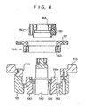
- the second embodiment directed to a driving shaft received in the shaft housing 120 is shown in FIG. 6 .
- the shaft sealing apparatus 200 comprises a driving shaft 240 in the form of a cylindrical shape and received in the shaft housing 120, not shown, to be movably supported by the shaft housing 120.
- the driving shaft 240 is held in coaxial alignment with the shaft housing 120 and rotatable around its own axis with respect to the shaft housing 120.
- the driving shaft 240 has a first axial end 240a extending in the vacuum chamber 111 of the vacuum casing 110, a second axial end, not shown, extending in the atmosphere 112, and an outer cylindrical surface 240b smaller in diameter than the inner cylindrical surface 120a of the shaft housing 120.
- the shaft sealing apparatus 200 further comprises a sealing unit 260 received in the opening 110b of the vacuum casing 110 and fixedly supported by the base portion 110a of the vacuum casing 110.
- the sealing unit 260 includes a retaining member 161 and a plurality of sealing rings 163. Each of the sealing rings 163 of the sealing unit 260 intervenes between the driving shaft 240 and the retaining member 161 of the sealing unit 260 to hermetically seal the gap between the driving shaft 240 and the retaining member 161 of the sealing unit 260.
- the sealing rings 163 of the sealing unit 260 are held in axially spaced-apart relationship with each other.
- the retaining member 161 of the sealing unit 260 has an inner cylindrical surface 161c larger in diameter than the outer cylindrical surface 240b of the driving shaft 240.
- the sealing lip 164c of the annular resilient member 164 is held in contact with the outer cylindrical surface 240b of the driving shaft 240.
- the annular spring member 165 of the sealing ring 163 is operative to impart a force to the sealing lip 164c of the annular resilient member 164 to ensure that the sealing lip 164c of the annular resilient member 164 is held in tight contact with the outer cylindrical surface 240b of the driving shaft 240.
- the outer cylindrical surface 240b of the driving shaft 240 is smaller in surface roughness Ra than 0.1 ⁇ m, and larger in Vickers hardness Hv than 650.
- the shaft sealing apparatus 200 further comprises a fixed member 280 in the form of an annular ring shape and provided on the retaining member 161 of the sealing unit 260.
- the fixed member 280 is fixedly connected with the retaining member 161 of the sealing unit 260 by bolts 281.
- the following description will be directed to a method of assembling the shaft sealing apparatus 200 with reference to the drawings shown in FIG. 6 .
- the method of assembling the shaft sealing apparatus 200 is performed through the steps including a preparing step and first and second installing steps as follows.
- the vacuum casing 110, the shaft housing 120, the driving shaft 240 are prepared as a partially assembled unit.
- the construction of the driving shaft 240 has been described in the above.
- the sealing unit 260 constituted by the retaining member 161 and the sealing rings 163 securely retained by the retaining member 161 is installed in the opening 110b of the vacuum casing 110.
- the construction of the sealing unit 260 has been described in the above.
- the fixed member 280 is installed on the retaining member 161 of the sealing unit 260.
- the construction of the fixed member 280 has been described in the above.
- the shaft sealing apparatus 200 is then assembled as shown in FIG. 6 .
- the second embodiment of the shaft sealing apparatus according to the present invention has an advantage and effect the same as that of the first embodiment of the shaft sealing apparatus according to the present invention.
- the shaft sealing apparatus 300 is available for a vacuum processing apparatus equipped with a handling mechanism.
- the shaft sealing apparatus 300 comprises a vacuum casing 310 formed with a vacuum chamber 311, and a shaft housing 320 in the form of a cylindrical hollow shape and fixedly connected with the vacuum casing 310.
- the vacuum casing 310 has a base portion 310a formed with an opening 310b to have the vacuum chamber 311 of the vacuum casing 310 held in communication with the atmosphere 312 through the opening 310b of the vacuum casing 310.
- the shaft housing 320 has a first axial end 320a extending in the vacuum chamber 311 of the vacuum casing 310, a second axial end, not shown, extending in the atmosphere 312, a flange portion 320b integrally formed with the first axial end 320a and radially outwardly extending from the first axial end 320a, and an inner cylindrical surface 320c formed with an annular ledge 320d connected with the first axial end 320a.
- the flange portion 320b of the shaft housing 320 is fixedly connected with the base portion 310a of the vacuum casing 310 by bolts 321.
- Each of the first axial end 320a of the shaft housing 320 and the flange portion 320b of the shaft housing 320 is exposed to the vacuum chamber 311 of the vacuum casing 310 to form part of the base portion 310a of the vacuum casing 310.
- the shaft sealing apparatus 300 further comprises a sleeve shaft 330 in the form of a cylindrical hollow shape and received in the shaft housing 320 to be movably supported by the shaft housing 320.
- the sleeve shaft 330 is held in coaxial alignment with the shaft housing 320 and rotatable around its own axis with respect to the shaft housing 320.
- the sleeve shaft 330 has a first axial end 330a extending in the vacuum chamber 311 of the vacuum casing 310, a second axial end, not shown, extending in the atmosphere 312, an outer cylindrical surface 330b smaller in diameter than the inner cylindrical surface 320c of the shaft housing 320, and an inner cylindrical surface 330c formed with an annular ledge 330d connected with the first axial end 330a.
- the sleeve shaft 330 constitutes a driving shaft having an outer cylindrical surface and movably extending in the vacuum chamber 311 of the vacuum casing 312.
- shaft sealing apparatus 300 has been described in the above as comprising a sleeve shaft 330 rotatable around its own axis with respect to the shaft housing 320, the sleeve shaft 330 may be replaced by a sleeve shaft axially movable ) along its own axis with respect to said shaft housing 320 according to the present invention.
- the shaft sealing apparatus 300 has been described in the above as comprising a sleeve shaft 330 in the form of a cylindrical hollow shape and received in the shaft housing 320 to be held in coaxial alignment with the shaft housing 320, the sleeve shaft 330 may be replaced by a plurality of sleeve shafts each in the form of a cylindrical hollow shape and received in the shaft housing 320 to be held in coaxial alignment with the shaft housing 320 according to the present invention.
- the shaft sealing apparatus 300 further comprises a center shaft 340 in the form of a cylindrical shape and received in the sleeve shaft 330 to be movably supported by the sleeve shaft 330.
- the center shaft 340 is held in coaxial alignment with the sleeve shaft 330 and rotatable around its own axis with respect to the sleeve shaft 330.
- the center shaft 340 has a first axial end 340a extending in the vacuum chamber 311 of the vacuum casing 310, a second axial end, not shown, extending in the atmosphere 312, and an outer cylindrical surface 340b smaller in diameter than the inner cylindrical surface 330c of the sleeve shaft 330.
- the center shaft 340 constitutes a driving shaft having an outer cylindrical surface and movably extending in the vacuum chamber 311 of the vacuum casing 312.
- the shaft sealing apparatus 300 has been described in the above as comprising a center shaft 340 rotatable around its own axis with respect to the sleeve shaft 330, the center shaft 340 may be replaced by a center shaft axially movable along its own axis with respect to said sleeve shaft 330 according to the present invention.
- the shaft sealing apparatus 300 further comprises a first sealing unit 350 received in the annular ledge 330d of the sleeve shaft 330 and fixedly supported by the sleeve shaft 330.
- the first sealing unit 350 includes a retaining member 351 in the form of an annular ring shape and fixedly supported by the sleeve shaft 330, and a plurality of sealing rings 153 securely retained by the retaining member 351 of the first sealing unit 350 to be held in axial alignment with each other.
- Each of the sealing rings 153 of the first sealing unit 350 is in the form of an annular ring shape and intervenes between the center shaft 340 and the retaining member 351 of the first sealing unit 350 to hermetically seal the gap between the center shaft 340 and the retaining member 351 of the first sealing unit 350.
- the sealing rings 153 of the first sealing unit 350 are held in contact with each other.
- the retaining member 351 of the first sealing unit 350 has a first axial end 351a extending in the vacuum chamber 311 of the vacuum casing 310, a second axial end 351b held in contact with the annular ledge 330d of the sleeve shaft 330, and an inner cylindrical surface 351c larger in diameter than the outer cylindrical surface 340b of the center shaft 340.
- the inner cylindrical surface 351c of the retaining member 351 is formed with an annular ledge 351d connected with the first axial end 351 a of the retaining member 351.
- Each of the sealing rings 153 of the first sealing unit 350 includes an annular resilient member 154 formed with an annular groove 154a, and an annular spring member 155 received in the annular groove 154a of the annular resilient member 154 and retained by the annular resilient member 154 as shown in FIG. 2 .
- the annular resilient member 154 of the sealing ring 153 has a peripheral portion 154b securely retained by the annular ledge 351d of the retaining member 351, and a sealing lip 154c integrally formed with the peripheral portion 154b of the annular resilient member 154 and radially inwardly extending from the peripheral portion 154b of the annular resilient member 154 to be held in contact with the outer cylindrical surface 340b of the center shaft 340.
- the sealing lip 154c of the annular resilient member 154 is made of a synthetic resin constituted by an ultra high molecular weight compound.
- the annular resilient member 154 of the sealing ring 153 may have a reinforcing portion 154d covered by a rubber and intervening between the peripheral portion 154b of the annular resilient member 154 and the sealing lip 154c of the annular resilient member 154 to have the resilient member 154 reinforced with the annular reinforcing portion 154d.
- the reinforcing portion 154d of the annular resilient member 154 is made of a metal plate in the form of an annular ring shape and 5 is of an L-shaped cross-section taken on the plane perpendicular to the center axis passing therethrough.
- the annular spring member 155 of the sealing ring 153 is operative to impart a force to the sealing lip 154c of the annular resilient member 154 to ensure that the sealing lip 154c of the annular resilient member 154 is held in tight contact with the outer cylindrical surface 340b of the center shaft 340.
- the annular spring member 155 of the sealing ring 153 is made of a metal wire in the form of a helical shape and is of a circular cross-section taken on the plane perpendicular to the center axis passing therethrough.
- the annular spring member 155 thus constructed is generally called "garter spring".
- the outer cylindrical surface 340b of the center shaft 340 is smaller in surface roughness Ra than 0.1 ⁇ m and larger in Vickers hardness Hv than 650.
- the sealing lip 154c of the annular resilient member 154 may be held in contact with the outer cylindrical surface 340b of the center shaft 340 with a vacuum grease constituted by a lubricant containing fluorine.
- the first sealing unit 350 may include a plurality of sealing rings 153 each having a sealing lip 154c coated with the vacuum grease.
- the first sealing unit 350 may also include a plurality of sealing rings 153 each having a sealing lip 154c to have the sealing lips 154c collectively form an annular groove filled with the vacuum grease.
- the first sealing unit 350 may also include a plurality of sealing rings 153 each having a sealing lip 154c and a subsidiary sealing lip held in contact with the outer cylindrical surface 340b of the center shaft 340 to have the sealing lip 154c and the subsidiary sealing lip collectively form an annular groove filled with the vacuum grease.
- the shaft sealing apparatus 300 further comprises a first bearing 359 ) intervening between the center shaft 340 and the sleeve shaft 330 to have the center shaft 340 movably supported by the sleeve shaft 330 through the first bearing 359.
- the first bearing 359 is located between the sealing ring 153 of the first sealing unit 350 and the second axial end of the center shaft 340 in axially spaced-apart relationship with the sealing ring 153 of the first sealing unit 350.
- the shaft sealing apparatus 300 further comprises first driving means constituted by an electric motor, not shown.
- the electric motor is operatively connected with the second axial end of the center shaft 340 to rotate the center shaft 340 around its own axis. While the driving means has been described in the above as being constituted by an electric motor operatively connected with the second axial end of the center shaft 340, the electric motor may be replaced by a reduction gear unit and an electric motor operatively connected with the second axial end of the center shaft 340 through the reduction gear unit.
- the shaft sealing apparatus 300 further comprises a second sealing unit 360 received in the annular ledge 320d of the shaft housing 320 and fixedly supported by the shaft housing 320.
- the second sealing unit 360 includes a retaining member 361 in the form of an annular ring shape and fixedly supported by the shaft housing 320, and a plurality of sealing rings 163 securely retained by the retaining member 361 of the second sealing unit 360 to be held in axial alignment with each other.
- Each of the sealing rings 163 of the second sealing unit 360 is in the form of an annular ring shape and intervenes between the sleeve shaft 330 and the retaining member 361 of the second sealing unit 360 to hermetically seal the gap between the sleeve shaft 330 and the retaining member 361 of the second sealing unit 360.
- the sealing rings 163 of the second sealing unit 360 are held in contact with each other.
- the retaining member 361 of the second sealing unit 360 has a first axial end 361a extending in the vacuum chamber 311 of the vacuum casing 310, a second axial end 361b held in contact with the annular ledge 320d of the shaft housing 320, and an inner cylindrical surface 361c larger in diameter than the outer cylindrical surface 351d of the sleeve shaft 330.
- the inner cylindrical surface 361c of the retaining member 361 is formed with an annular ledge 361d connected with the first axial end 361a of the retaining member 361.
- Each of the sealing ring 163 of the second sealing unit 360 includes an annular resilient member 164 formed with an annular groove 164a, and an annular spring member 165 received in the annular groove 164a of the annular resilient member 164 and retained by the annular resilient member 164 as shown in FIG. 2 .
- the annular resilient member 164 of the sealing ring 163 has a peripheral portion 164b securely retained by the annular ledge 361d of the retaining member 361, and a sealing lip 164c integrally formed with the peripheral portion 164b of the annular resilient member 164 and radially inwardly extending from the peripheral portion 164b of the annular resilient member 164 to be held in contact with the outer cylindrical surface 330b of the sleeve shaft 330.
- the sealing lip 164c of the annular resilient member 164 is made of a synthetic resin constituted by an ultra high molecular weight compound.
- the annular resilient member 164 of the sealing ring 163 may have a reinforcing portion 164d covered by a rubber and intervening between the peripheral portion 164b of the annular resilient member 164 and the sealing lip 164c of the annular resilient member 164 to have the annular resilient member 164 reinforced with the reinforcing portion 164d.
- the reinforcing portion 164d of the annular resilient member 164 is made of a metal plate in the form of an annular ring shape and is of an L-shaped cross-section taken on the plane perpendicular to the center axis passing therethrough.
- the annular spring member 165 of the sealing ring 163 is operative to impart a force to the sealing lip 164c of the annular resilient member 164 to ensure that the sealing lip 164c of the annular resilient member 164 is held in tight contact with the outer cylindrical surface 330b of the sleeve shaft 330.
- the annular spring member 165 of the sealing ring 163 is made of a metal wire in the form of a helical shape and is of a circular cross-section taken on the plane perpendicular to the center axis passing therethrough.
- the annular spring member 165 thus constructed is generally called "garter spring".
- the outer cylindrical surface 330b of the sleeve shaft 330 is smaller in surface roughness Ra than 0.1 ⁇ m and larger in Vickers hardness Hv than 650.
- the sealing lip 164c of the annular resilient member 164 may be held in contact with the outer cylindrical surface 330b of the sleeve shaft 330 with a vacuum ) grease constituted by a lubricant containing fluorine.
- the second sealing unit 360 may include a plurality of sealing rings 163 each having a sealing lip 164c coated with the vacuum grease.
- the second sealing unit 360 may also include a plurality of sealing rings 163 each having a sealing lip 164c to have the sealing lips 164c collectively form an annular groove filled with the vacuum grease.
- the second sealing unit 360 may also include a plurality of sealing rings 163 each having a sealing lip 164c and a subsidiary sealing lip held in contact with the outer cylindrical surface 330b of the sleeve shaft 330 to have the sealing lip 164c and the subsidiary sealing lip collectively form an annular groove filled with the vacuum grease.
- the shaft sealing apparatus 300 further comprises a second bearing 369 intervening between the sleeve shaft 330 and the shaft housing 320 to have the sleeve shaft 330 movably supported by the shaft housing 320 through the second bearing 369.
- the second bearing 369 is located between the sealing ring 163 of the second sealing unit 360 and the second axial end of the sleeve shaft 330 in axially spaced-apart relationship with the sealing ring 163 of the second sealing unit 360.
- the shaft sealing apparatus 300 further comprises second driving means constituted by an electric motor, not shown.
- the electric motor is operatively connected with the second axial end of the sleeve shaft 330 to rotate the sleeve shaft 330 around its own axis. While the driving means has been described in the above as being constituted by an electric motor operatively connected with the second axial end of the sleeve shaft 330, the electric motor may be replaced by a reduction gear unit and an electric motor operatively connected with the second axial end of the sleeve shaft 330 through the reduction gear unit.
- the shaft sealing apparatus 300 further comprises a first labyrinth seal unit 371 intervening between the sleeve shaft 330 and the center shaft 340 to be exposed to the vacuum chamber 311 of the vacuum casing 310, and a second labyrinth seal unit 372 intervening between the shaft housing 320 and the sleeve shaft 330 to be exposed to the vacuum chamber 311 of the vacuum casing 310.
- the first labyrinth seal unit 371 includes an outer ring member 373 provided on the first axial end 330a of the sleeve shaft 330, and an inner ring member 374 provided on the first axial end 340a of the center shaft 340.
- the outer and inner ring members 373 and 374 of the first labyrinth seal unit 371 collectively form an interstice 375 therebetween to be operative to prevent dust, oil and gas from passing through the interstice 375 of the first labyrinth seal unit 371.
- the second labyrinth seal unit 372 includes an outer ring member 376 provided on the first axial end 320a of the shaft housing 320, and an inner ring member 377 provided on the first axial end 330a of the sleeve shaft 330.
- the outer and inner ring members 376 and 377 of the second labyrinth seal unit 372 collectively form an interstice 378 therebetween to be operative to prevent dust, oil and gas from passing through the interstice 378 of the second labyrinth seal unit 372.
- the shaft sealing apparatus 300 further comprises a first fixed member 381 in the form of an annular ring shape and provided on the first axial end 330a of the sleeve shaft 330, a second fixed member 382 in the form of an annular ring shape and provided on the first axial end 320a of the shaft housing 320, and a base member 390 in the form of a circular shape and provided on the first axial end 340a of the center shaft 340.
- the second fixed member 382 is held in axial alignment with the shaft housing 320 and fixedly connected with the first axial end 320a of the shaft housing 320 by bolts 387.
- the second fixed member 382 has an inner portion 388 formed with a projection, and a flange portion 389 operative to prevent the sealing rings 163 of the second sealing unit 360 from moving toward the vacuum chamber 311 of the vacuum casing 310 with respect to the sleeve shaft 330.
- the inner portion 388 of the second fixed member 382 constitutes the outer ring member 376 of the second labyrinth seal unit 372.
- the second fixed member 382 projects from the base portion 310a of the vacuum casing 310 and extends in the vacuum chamber 311 of the vacuum casing 310.
- the second fixed member 382 forms part of the shaft housing 320 extending in the vacuum chamber 311 of the vacuum casing 310.
- the second fixed member 382 is fixedly connected with the retaining member 361 of the second sealing unit 360 by bolts 396 to be operative to prevent the retaining member 361 of the second sealing unit 360 from rotating around its own axis with respect to the shaft housing 320.
- the first fixed member 381 is held in axial alignment with the sleeve shaft 330 and fixedly connected with the first axial end 330a of the sleeve shaft 330 by bolts 383.
- the first fixed member 381 has an outer portion 384 formed with a pit to fit with the projection of the inner portion 388 of the second fixed member 382, an inner portion 385 formed with a projection, and a flange portion 386 operative to prevent the sealing rings 153 of the first sealing unit 350 from moving toward the vacuum chamber 311 of the vacuum casing 310 with respect to the center shaft 340.
- the outer portion 384 of the first fixed member 381 constitutes the inner ring member 377 of the second labyrinth seal unit 372.
- the inner portion 385 of the first fixed member 381 constitutes the outer ring member 373 of the first labyrinth seal unit 371.
- the first fixed member 381 projects from the first axial end 320a of the shaft housing 320 and extends in the vacuum chamber 311 of the vacuum casing 310 to be operatively connected with the handling mechanism, not shown.
- the first fixed member 381 forms part of the sleeve shaft 330 extending in the vacuum chamber 311 of the vacuum casing 310.
- the first fixed member 381 is fixedly connected with the retaining member 351 of the first sealing unit 350 by bolts 395 to be operative to prevent the retaining member 351 of the first sealing unit 350 from rotating around its own axis with respect to the sleeve shaft 330.
- the base member 390 is held in axial alignment with the center shaft 340 and fixedly connected with the first axial end 340a of the center shaft 340 by bolts 391.
- the base member 390 has an outer portion 392 formed with a pit to fit with the projection of the inner portion 385 of the first fixed member 381.
- the base member 390 projects from the first axial end 330a of the sleeve shaft 330 and extends in the vacuum chamber 311 of the vacuum casing 310 to be operatively connected with the handling mechanism, not shown.
- the base member 390 forms part of the center shaft 340 extending in the vacuum chamber 311 of the vacuum casing 310.
- the outer portion 392 of the base member 390 constitutes the inner ring member 374 of the first labyrinth seal unit 371.
- the base member 390 and the first fixed member 381 collectively constitute the first labyrinth seal unit 371, and the first and second fixed members 381 and 382 collectively constitute the second labyrinth seal unit 372.
- the handling mechanism is disposed in the vacuum chamber 311 of the vacuum casing 310 and includes a handling member pivotally supported by the first fixed member 381 and the base member 390 to be operative to handle wafers and other substrates in the vacuum chamber 311 of the vacuum casing 310.
- the sealing ring 153 has been described in the above as including an annular spring member 155 made of a metal wire in the form of a helical shape as shown in FIG. 2
- the annular spring member 155 may be replaced by an annular spring member made of a metal plate in the form of an annular ring shape as shown in FIG. 3 according to the present invention.
- the sealing ring 153 of the first sealing unit 350 includes an annular resilient member 156 formed with an annular groove 156a, and an annular spring member 157 received in the annular groove 156a of the annular resilient member 156 and retained by the annular resilient member 156.
- the annular resilient member 156 of the sealing ring 153 has a peripheral portion 156b securely retained by the annular ledge 351d of the retaining member 351, and a sealing lip 156c integrally formed with the peripheral portion 156b of the annular resilient member 156 and radially inwardly extending from the peripheral portion 156b of the annular resilient member 156 to be held in contact with the outer cylindrical surface 340b of the center shaft 340.
- the sealing lip 156c of the annular resilient member 156 is made of a synthetic resin constituted by an ultra high molecular weight compound.
- the annular resilient member 156 of the sealing ring 153 may have a flange portion 156d integrally formed with the peripheral portion 156b of the annular resilient member 156 and radially outwardly extending from the peripheral portion 156b of the annular resilient member 156.
- the flange portion 156d of the annular resilient member 156 is held in contact with the retaining member 351 of the first sealing unit 350 to hermetically seal the gap between the center shaft 340 and the retaining member 351 of the first sealing unit 350.
- the annular spring member 157 of the sealing ring 153 is operative to impart a force to the sealing lip 156c of the annular resilient member 156 to ensure that the sealing lip 156c of the annular resilient member 156 is held in tight contact with the outer cylindrical surface 340b of the center shaft 340.
- the annular spring member 157 of the sealing ring 153 is made of a metal plate in the form of an annular ring shape and is of a channel-shaped cross-section taken on the plane perpendicular to the center axis passing therethrough.
- the annular spring member 157 thus constructed is generally called "cantilever spring".
- the sealing ring 163 has been described in the above as including an annular spring member 165 made of a metal wire in the form of a helical shape as shown in FIG. 2
- the annular spring member 165 may be also replaced by an annular spring member made of a metal plate in the form of an annular ring shape as shown in FIG. 3 according to the present invention.
- the shaft sealing apparatus 300 may further comprise an intermediate shaft housing intervening between the shaft housing 320 and the sleeve shaft 330 according to the present invention.
- the intermediate shaft housing is axially movably supported by the shaft housing 320 and rotatably supports the sleeve shaft 330 to ensure that the sleeve shaft 330 is rotatable and axially movable with respect to the shaft housing 320.
- the following description will be directed to a method of assembling the shaft sealing apparatus 300 with reference to the drawing shown in FIG. 7 .
- the method of assembling the shaft sealing apparatus 300 is performed through the steps including a preparing step and first to third installing steps as follows.
- the vacuum casing 310, the shaft housing 320, the sleeve shaft 330, the center shaft 340, the first bearing 359, and the second bearing 369 are prepared as a partially assembled unit.
- the constructions of the vacuum casing 310, the shaft housing 320, the sleeve shaft 330, the center shaft 340, the first bearing 359, and the second bearing 369 have been described in the above.
- the first sealing unit 350 constituted by the retaining member 351 and the sealing rings 153 securely retained by the retaining member 351 is installed in the annular ledge 330d of the shaft housing 330
- the second sealing unit 360 constituted by the retaining member 361 and the sealing rings 163 securely retained by the retaining member 361 is installed in the annular ledge 320d of the shaft housing 320.
- the second fixed member 382 is installed on the first axial end 320a of the shaft housing 320, and the first fixed member 381 is installed on the first axial end 330a of the sleeve shaft 330.
- the second labyrinth seal unit 372 is then installed between the shaft housing 320 and the sleeve shaft 330 to be exposed to the vacuum chamber 311 of the vacuum casing 310.
- the constructions of the first and second fixed members 381 and 382, and the second labyrinth seal unit 372 have been described in the above.
- the base member 390 is installed on the first axial end 340a of the center shaft 340.
- the first labyrinth seal unit 371 is then installed between the sleeve shaft 330 and the center shaft 340 to be exposed to the vacuum chamber 311 of the vacuum casing 310.
- the constructions of the base member 390 and the first labyrinth seal unit 371 have been described in the above.
- the shaft sealing apparatus 300 is then assembled as shown in FIG. 7 .
- the fact that the outer cylindrical surface of the driving shaft is smaller in surface roughness Ra than 0.1 ⁇ m and larger in Vickers hardness Hv than 650 leads to the fact that the third embodiment of the shaft sealing apparatus according to the present invention makes it possible (1) to be excellent in characteristic to seal the gaps between the driving shaft and other parts around the driving shaft within a tolerance (less than 1 ⁇ 10 -9 Pa m 3 /s).
- the sealing lip of the sealing ring is made of a synthetic resin constituted by an ultra high molecular weight compound leads to the fact that the third embodiment of the shaft sealing apparatus according to the present invention makes it possible (2) to check the flow of gas.
- each of the sealing units is installed in the shaft sealing apparatus separately leads to the fact that the third embodiment of the shaft sealing apparatus according to the present invention makes it possible (3) to be simple in construction, (4) to be reduced in size, (5) to be reduced in production cost, (6) to be assembled with facility, (7) to eliminate the need of centering of the sealing unit, and (8) to prevent the sealing lip from breaking.
- the fact that each of the labyrinth seal units is installed in the shaft sealing apparatus leads to the fact that the third embodiment of the shaft sealing apparatus according to the present invention makes it possible (9) to prevent dust, oil and gas from passing through the interstice of the labyrinth seal unit.
- each of the base member and the first fixed member collectively constitute the first labyrinth seal unit, and the first and second fixed members collectively constitute the second labyrinth seal unit leads to the fact that the third embodiment of the shaft sealing apparatus according to the present invention makes it possible (10) to be reduced in parts count, and (11) to be reduced in size.
Landscapes
- Engineering & Computer Science (AREA)
- General Engineering & Computer Science (AREA)
- Mechanical Engineering (AREA)
- Sealing With Elastic Sealing Lips (AREA)
- Sealing Devices (AREA)
- Sealing Of Bearings (AREA)
- Heat Treatment Of Articles (AREA)
- Vacuum Packaging (AREA)
- Container, Conveyance, Adherence, Positioning, Of Wafer (AREA)
- Manipulator (AREA)
- Gasket Seals (AREA)
Claims (10)
- Un appareil d'étanchéité pour arbre, comprenant :une gaine à vide (110 ; 310) formée dans celui-ci avec une ouverture (110b ; 310b) et une chambre à vide (111 ; 311) pouvant être maintenue à un niveau de pression inférieur à 10-1 Pa ;un arbre d'entraînement (130, 140 ; 240 ; 330, 340) ayant une surface cylindrique externe (151d, 140b ; 240b ; 330b, 340b) et s'étendant de façon à pouvoir se déplacer dans ladite chambre à vide (111 ; 311) de ladite gaine à vide (110) à travers ladite ouverture (110b ; 310b) de ladite gaine à vide (110 ; 310) ;un anneau d'étanchéité (153, 163) sous la forme d'une configuration en anneau annulaire et incluant une lèvre d'étanchéité ((154c, 164c) ou 156c) maintenue en contact avec ladite surface cylindrique externe (151d, 140b ; 240b ; 330b, 340b) dudit arbre d'entraînement (130, 140 ; 240 ; 330, 340), etun élément formant ressort annulaire ((155, 165) ou 157) fonctionnant pour transmettre une force à ladite lèvre d'étanchéité ((154c, 164c) ou 156c) pour faire en sorte que ladite lèvre d'étanchéité ((154c, 164c) ou 156c) soit maintenue en contact étroit avec ladite surface cylindrique externe (151d, 140b ; 240b ; 330b, 340b) dudit arbre d'entraînement (130, 140 ; 240 ; 330, 340), caractérisé en ce queune portion périphérique ((154b, 164b) ou 156b) s'étend vers l'extérieur de façon radiale depuis ladite lèvre d'étanchéité ((154c, 164c) ou 156c),ladite surface cylindrique externe (151 d, 140b ; 240b ; 330b, 340b) dudit arbre d'entraînement (130, 140 ; 240 ; 330, 340) a une rugosité de surface Ra inférieure à 0,1 (µm),ladite surface cylindrique externe (151 d, 140b ; 240b ; 330b, 340b) dudit arbre d'entraînement (130, 140 ; 240 ; 330, 340) a une dureté Vickers Hv supérieure à 650, etl'appareil comprenant en outre un élément de retenue annulaire (151 ; 161 ; 351, 361) retenant solidement ladite portion périphérique ((154b, 164b) ou 156b) dudit anneau d'étanchéité (163, 153) pour constituer une unité d'étanchéité (150, 160 ; 260 ; 360, 350) avec ledit anneau d'étanchéité (163, 153), ladite unité d'étanchéité (160, 150 ; 260 ; 360, 350) étant installée dans ladite ouverture (110b ; 310b) de ladite gaine à vide (110 ; 310) afin d'être coaxiale avec ledit arbre d'entraînement (130, 140 ; 240 ; 330, 340) et raccordée de façon fixe à ladite gaine à vide (110 ; 310), et ledit anneau d'étanchéité (163, 153) intervenant entre ladite surface cylindrique externe (130b, 140b ; 240b ; 330b, 340b) dudit arbre d'entraînement (130, 140 ; 240 ; 330, 340) et ledit élément de retenue (151 ; 161 ; 351, 361) afin de fermer hermétiquement l'écart entre ledit arbre d'entraînement (130 ; 240 ; 330) et ledit élément de retenue (151 ; 161 ; 351, 361) dans les limites d'une tolérance inférieure à 1 x 10⁻⁹ Pa m3/s.
- Un appareil d'étanchéité pour arbre tel qu'exposé dans la revendication 1, lequel comprend en outre un élément creux cylindrique (120, 130 ; 320, 330) dans lequel ledit arbre d'entraînement (130, 140 ; 330, 340) est soutenu de façon à ce qu'il puisse tourner.
- Un appareil d'étanchéité pour arbre tel qu'exposé dans la revendication 1, dans lequel ledit élément formant ressort annulaire (155, 165) dudit anneau d'étanchéité (153, 163) est réalisé dans un fil métallique sous la forme d'une configuration hélicoïdale et est de coupe transversale circulaire prise dans le plan perpendiculaire à l'axe central traversant celui-ci.
- Un appareil d'étanchéité pour arbre tel qu'exposé dans la revendication 1, dans lequel ledit élément formant ressort annulaire (157) dudit anneau d'étanchéité (153, 163) est réalisé dans une plaque métallique sous la forme d'une configuration en anneau annulaire et est de coupe transversale configurée en canal prise dans le plan perpendiculaire à l'axe central traversant celui-ci.
- Un appareil d'étanchéité pour arbre tel qu'exposé dans la revendication 1 ou 2, dans lequel ladite lèvre d'étanchéité ((154c, 164c) ou 156c) dudit anneau d'étanchéité (153, 163) est réalisée en une résine synthétique constituée d'un composé à poids moléculaire ultra-élevé.
- Un appareil d'étanchéité pour arbre tel qu'exposé dans la revendication 2, lequel comprend en outre un palier (169, 159 ; 369, 359) situé entre ledit arbre d'entraînement et ledit élément creux cylindrique (120, 130), et espacé de façon axiale dudit anneau d'étanchéité (163,153) de ladite unité d'étanchéité (160, 150 ; 360, 350).
- Un appareil d'étanchéité pour arbre tel qu'exposé dans la revendication 1, dans lequel ledit arbre d'entraînement (130 ; 330) est sous la forme d'une configuration creuse cylindrique et a, au niveau de sa première extrémité axiale, un élément de retenue annulaire additionnel (151 ; 351) raccordé de façon coaxiale et fixe à celui-ci, et qui comprend en outre
un arbre central cylindrique (140 ; 340) reçu de façon à pouvoir se déplacer dans ledit arbre d'entraînement creux cylindrique (130 ; 330) et maintenu en alignement coaxial avec ledit arbre d'entraînement (130), et
un anneau d'étanchéité additionnel (153) sous la forme d'une configuration en anneau annulaire et retenu solidement par ledit élément de retenue additionnel (151 ; 351), ledit anneau d'étanchéité additionnel (153) incluant une lèvre d'étanchéité (154c ou 156c) maintenue en contact avec ladite surface cylindrique externe (140b ; 340b) dudit arbre central cylindrique (140 ; 340), un élément formant ressort annulaire (155 ou 157) fonctionnant pour transmettre une force à ladite lèvre d'étanchéité (154c ou 156c) pour faire en sorte que ladite lèvre d'étanchéité (154c ou 156c) soit maintenue en contact étroit avec ladite surface cylindrique externe (140b ; 340b) dudit arbre central cylindrique (140 ; 340), et une portion périphérique (154b ou 156b) s'étendant vers l'extérieur de façon radiale depuis ladite lèvre d'étanchéité (154c ou 156c) et raccordée de façon fixe audit élément de retenue annulaire additionnel (151 ; 351), et ledit anneau d'étanchéité additionnel (153) intervenant entre la surface cylindrique externe (140b ; 340b) dudit arbre central (140 ; 340) et ledit élément de retenue additionnel (151 ; 351) afin de fermer hermétiquement l'écart entre ledit arbre central (140 ; 340) et ledit arbre d'entraînement (130 ; 330). - Un appareil d'étanchéité pour arbre tel qu'exposé dans la revendication 7, dans lequel ladite surface cylindrique externe (151d) dudit arbre d'entraînement (130) est formée dans ledit élément de retenue annulaire additionnel (151) pour être en contact avec ledit anneau d'étanchéité (163).
- Un appareil d'étanchéité pour arbre tel qu'exposé dans la revendication 1, dans lequel ledit arbre d'entraînement (130, 140 ; 240 ; 330, 340) peut tourner autour ou se déplacer de façon axiale le long de son propre axe par rapport audit logement d'arbre (120).
- Un appareil d'étanchéité pour arbre tel qu'exposé dans la revendication 7, dans lequel ledit arbre central (140 ; 340) peut tourner autour ou se déplacer de façon axiale le long de son propre axe par rapport audit arbre d'entraînement creux cylindrique (130).
Applications Claiming Priority (3)
| Application Number | Priority Date | Filing Date | Title |
|---|---|---|---|
| JP2000324831 | 2000-10-25 | ||
| JP2001291877A JP2002228010A (ja) | 2000-10-25 | 2001-09-25 | 真空シール機構および真空シール装置 |
| EP01309001A EP1201975B1 (fr) | 2000-10-25 | 2001-10-23 | Dispositif d'étanchéité pour arbre |
Related Parent Applications (1)
| Application Number | Title | Priority Date | Filing Date |
|---|---|---|---|
| EP01309001A Division EP1201975B1 (fr) | 2000-10-25 | 2001-10-23 | Dispositif d'étanchéité pour arbre |
Publications (2)
| Publication Number | Publication Date |
|---|---|
| EP1640645A1 EP1640645A1 (fr) | 2006-03-29 |
| EP1640645B1 true EP1640645B1 (fr) | 2008-11-19 |
Family
ID=26602702
Family Applications (2)
| Application Number | Title | Priority Date | Filing Date |
|---|---|---|---|
| EP01309001A Expired - Lifetime EP1201975B1 (fr) | 2000-10-25 | 2001-10-23 | Dispositif d'étanchéité pour arbre |
| EP05028506A Expired - Lifetime EP1640645B1 (fr) | 2000-10-25 | 2001-10-23 | Dispositif d'étanchéité pour arbre |
Family Applications Before (1)
| Application Number | Title | Priority Date | Filing Date |
|---|---|---|---|
| EP01309001A Expired - Lifetime EP1201975B1 (fr) | 2000-10-25 | 2001-10-23 | Dispositif d'étanchéité pour arbre |
Country Status (9)
| Country | Link |
|---|---|
| US (2) | US7090222B2 (fr) |
| EP (2) | EP1201975B1 (fr) |
| JP (1) | JP2002228010A (fr) |
| KR (1) | KR100570960B1 (fr) |
| CN (1) | CN1327150C (fr) |
| AT (2) | ATE414863T1 (fr) |
| DE (2) | DE60120876T2 (fr) |
| HK (1) | HK1044362B (fr) |
| TW (1) | TW505756B (fr) |
Families Citing this family (68)
| Publication number | Priority date | Publication date | Assignee | Title |
|---|---|---|---|---|
| US6186507B1 (en) | 1997-09-25 | 2001-02-13 | Michael R. Oldenburg | Retrofittable severe duty seal for a shaft |
| US20020011710A1 (en) | 1997-09-25 | 2002-01-31 | Oldenburg Michael R. | Retrofittable severe duty seal for a shaft |
| US6692007B2 (en) | 2001-10-31 | 2004-02-17 | Transcom, Inc. | Seal for a shaft |
| US8979093B2 (en) | 2002-06-21 | 2015-03-17 | Inpro/Seal, LLC | Pressure balanced shaft seal assembly |
| US9004491B2 (en) | 2002-06-21 | 2015-04-14 | Inpro/Seal Llc | Shaft seal assembly |
| US7396017B2 (en) * | 2002-06-21 | 2008-07-08 | Isotech Of Illinois, Inc. | Shaft seal assembly |
| US7726661B2 (en) | 2002-06-21 | 2010-06-01 | Inpro/Seal Llc | Pressure balanced shaft seal assembly |
| KR20040016462A (ko) * | 2002-08-17 | 2004-02-25 | 주식회사 피엠시코리아 | 분산탱크의 축 밀봉장치 |
| US7063193B2 (en) * | 2002-09-25 | 2006-06-20 | Tochigi Fuji Sangyo Kabushiki Kaisha | Seal structure for relatively rotational members |
| DE20217983U1 (de) * | 2002-11-20 | 2003-02-13 | Burgmann Dichtungswerke GmbH & Co. KG, 82515 Wolfratshausen | Sekundärdichtungselement |
| DE10319821B4 (de) * | 2003-05-03 | 2008-01-24 | Reinhard Feinmechanik Gmbh | Wellendichtungsmodul zum Abdichten von Vakuumräumen |
| JP2005299808A (ja) * | 2004-04-13 | 2005-10-27 | Nok Corp | ポンプ用シール |
| CN101375385B (zh) | 2006-01-13 | 2012-05-30 | 纳博特斯克株式会社 | 包括冷却循环路径的基板搬运机器人的驱动设备 |
| JP5042515B2 (ja) * | 2006-03-22 | 2012-10-03 | 株式会社Sen | 真空駆動軸の真空シール機構 |
| EP2006582B1 (fr) | 2006-04-06 | 2013-05-22 | IHI Corporation | Structure d'etancheite pour appareil de traitement de refroidissement ou appareil de traitement thermique a chambres multiples, et pour la structure d'etancheite, procede de regulation de pression et procede de fonctionnement |
| US8033549B2 (en) * | 2006-04-25 | 2011-10-11 | Scenic Precise Element Inc. | Mechanical seal |
| US20070246891A1 (en) * | 2006-04-25 | 2007-10-25 | Cheng-Shiou Huang | Shaft-sealing device having an inner sealing-ring positioning assembly for a rotary machine |
| JP2008055560A (ja) * | 2006-08-31 | 2008-03-13 | Fanuc Ltd | ロボットの関節部の密封装置及び関節ロボット |
| GB0623326D0 (en) * | 2006-11-22 | 2007-01-03 | British Engines Ltd | Metal stem seal |
| EP1939485B1 (fr) * | 2006-12-29 | 2010-11-10 | Aktiebolaget SKF | Unité d'étanchéité et de guidage pour la tige d'un amortisseur monotubulaire |
| DE112007003556T5 (de) * | 2007-06-20 | 2010-05-20 | Harmonic Drive Systems Inc. | Motor mit Schneidwerkzeug-Befestigungsöffnung |
| CN101158437B (zh) * | 2007-10-31 | 2010-05-19 | 天津市亚安科技电子有限公司 | 室外云台旋转轴的防水结构 |
| DE102008025725A1 (de) * | 2008-05-29 | 2009-12-10 | Rothe Erde Gmbh | Dichtungssystem |
| EP2218998B1 (fr) * | 2009-02-03 | 2012-12-19 | Ipsen, Inc. | Mécanisme d'étanchéité pour four de traitement à la chaleur sous vide |
| US8297191B2 (en) * | 2009-07-31 | 2012-10-30 | The United States Of America As Represented By The Secretary Of The Navy | Pressure seal |
| MX2012006088A (es) * | 2009-12-11 | 2012-06-19 | Saint Gobain Performance Plast | Sistema, metodo y aparato para montaje de cierre dinamico movido por muelle. |
| DE102010006896A1 (de) * | 2010-02-05 | 2011-08-11 | Robert Bosch GmbH, 70469 | Dichtung |
| DE102010018255A1 (de) * | 2010-04-23 | 2011-10-27 | Imo Holding Gmbh | Dichtungsanordnung für Wälzlager |
| US8240672B2 (en) | 2010-05-07 | 2012-08-14 | Flowserve Management Company | Low breakout friction energized gasket |
| DE102010020139A1 (de) * | 2010-05-11 | 2011-11-17 | Maschinenfabrik Reinhausen Gmbh | Transformatordurchführung |
| US8454058B2 (en) * | 2010-08-09 | 2013-06-04 | GM Global Technology Operations LLC | High pressure fitting for hydrogen applications |
| DE102011113292A1 (de) * | 2011-09-05 | 2013-03-07 | Schmid Vacuum Technology Gmbh | Vakuumdurchführung und Vakuumbeschichtungsvorrichtung mit Vakuumdurchführungen |
| US9202733B2 (en) | 2011-11-07 | 2015-12-01 | Persimmon Technologies Corporation | Robot system with independent arms |
| CN103946350B (zh) * | 2011-11-23 | 2016-08-17 | Abb研究有限公司 | 密封系统,具有密封系统的工业机器人,以及用于提供密封表面的方法 |
| TW201530025A (zh) | 2013-09-30 | 2015-08-01 | Inpro Seal Llc | 軸封總成 |
| WO2015073647A1 (fr) | 2013-11-13 | 2015-05-21 | Brooks Automation, Inc. | Mécanisme d'entraînement de robot scellé |
| TWI695447B (zh) | 2013-11-13 | 2020-06-01 | 布魯克斯自動機械公司 | 運送設備 |
| US10348172B2 (en) | 2013-11-13 | 2019-07-09 | Brooks Automation, Inc. | Sealed switched reluctance motor |
| KR20230116962A (ko) | 2013-11-13 | 2023-08-04 | 브룩스 오토메이션 인코퍼레이티드 | 브러쉬리스 전기 기계 제어 방법 및 장치 |
| JP6024647B2 (ja) * | 2013-12-10 | 2016-11-16 | 日本精工株式会社 | 回転機構、回転駆動装置、搬送装置及び製造装置 |
| WO2015087925A1 (fr) * | 2013-12-10 | 2015-06-18 | 日本精工株式会社 | Mécanisme de joint d'étanchéité, dispositif d'entraînement pour mécanisme de joint d'étanchéité, dispositif de transport et dispositif de fabrication |
| CN105765277B (zh) * | 2013-12-10 | 2017-11-17 | 日本精工株式会社 | 密封机构、密封机构的驱动装置、输送装置和制造装置 |
| JP6015715B2 (ja) * | 2013-12-10 | 2016-10-26 | 日本精工株式会社 | シール機構、シール機構の駆動装置、搬送装置及び製造装置 |
| JP6020435B2 (ja) * | 2013-12-10 | 2016-11-02 | 日本精工株式会社 | 回転機構、回転駆動装置、搬送装置及び製造装置 |
| CN105765276B (zh) * | 2013-12-10 | 2018-02-02 | 日本精工株式会社 | 密封机构、密封机构的驱动装置、输送装置和制造装置 |
| AU2013408176B9 (en) * | 2013-12-18 | 2017-11-02 | Halliburton Energy Services, Inc. | Rotary seal assembly for accommodating radial deflection and tilting |
| DE102014000465A1 (de) * | 2014-01-16 | 2015-07-16 | Mtu Friedrichshafen Gmbh | Ladeluftleitung |
| CA3053128C (fr) * | 2014-07-09 | 2021-10-19 | Saint-Gobain Performance Plastics Corporation | Joint d'etancheite en polymere |
| DE102015003048B4 (de) | 2015-01-26 | 2021-10-28 | Sew-Eurodrive Gmbh & Co Kg | Dichtungsanordnung für Getriebe und Getriebe mit einer solchen Dichtungsanordnung |
| US9927034B2 (en) * | 2015-08-25 | 2018-03-27 | Mueller International, Llc | Valve seat stiffener |
| JP6565499B2 (ja) * | 2015-08-31 | 2019-08-28 | 日本精工株式会社 | シール構造、回転駆動装置、搬送装置、工作機械および半導体製造装置 |
| CA2989756A1 (fr) * | 2016-12-22 | 2018-06-22 | Joy Global Surface Mining Inc | Egaliseur dote de lubrification |
| DE102017100507B4 (de) * | 2017-01-12 | 2021-11-25 | Ald Vacuum Technologies Gmbh | Vorrichtung und Verfahren zur Beschichtung von Werkstücken |
| EP3652456B1 (fr) * | 2017-07-12 | 2021-06-09 | Johnson Controls Technology Company | Paliers auxiliaires à auto-centrage dans une cartouche de palier magnétique |
| CN109307077B (zh) * | 2017-07-27 | 2022-11-29 | 舍弗勒技术股份两合公司 | 密封组件 |
| JP6538788B2 (ja) * | 2017-09-13 | 2019-07-03 | ファナック株式会社 | 異物の侵入を抑制する電動機 |
| US20190202684A1 (en) * | 2017-12-29 | 2019-07-04 | Texas Instruments Incorporated | Protective bondline control structure |
| EP3543568B1 (fr) * | 2018-03-19 | 2021-01-06 | Carl Freudenberg KG | Bague d'étanchéité, dispositif formant bague d'étanchéité et utilisation d'un dispositif formant bague d'étanchéité |
| CN108411372A (zh) * | 2018-05-04 | 2018-08-17 | 常州比太黑硅科技有限公司 | 一种真空腔室腔内升降机构 |
| TWI735960B (zh) | 2018-09-28 | 2021-08-11 | 美商英普羅密封有限責任公司 | 環狀密封組件 |
| DE102019110034A1 (de) * | 2019-04-16 | 2020-10-22 | Carl Freudenberg Kg | Dichtungsbalg |
| EP4006388A4 (fr) | 2019-07-24 | 2023-07-26 | NOK Corporation | Dispositif d'étanchéité |
| EP4330567A4 (fr) * | 2021-04-30 | 2024-12-18 | Abb Schweiz Ag | Ensemble d'étanchéité et robot |
| CN116025638A (zh) * | 2021-10-26 | 2023-04-28 | 舍弗勒技术股份两合公司 | 密封装置 |
| CN114392694A (zh) * | 2021-12-27 | 2022-04-26 | 南通海嘉智能科技有限公司 | 天然气水合物合成装置的密封结构 |
| JP7135224B1 (ja) * | 2022-01-12 | 2022-09-12 | Nok株式会社 | ハブシールの製造方法 |
| CN114311015B (zh) * | 2022-02-16 | 2024-11-22 | 深圳市越疆科技有限公司 | 关节模组的密封结构、关节模组、机械臂和机器人 |
| CN116292897B (zh) * | 2023-01-29 | 2025-09-30 | 中国原子能科学研究院 | 动态密封装置及内压试验炉 |
Family Cites Families (36)
| Publication number | Priority date | Publication date | Assignee | Title |
|---|---|---|---|---|
| US2804325A (en) * | 1954-07-16 | 1957-08-27 | Gen Motors Corp | Fluid seal |
| US3128887A (en) | 1960-02-25 | 1964-04-14 | Mechanical manipulators for the displacement of | |
| BE637617A (fr) | 1963-09-19 | 1964-03-19 | Acec | Joint d'etanchéité rotatif |
| US3347604A (en) | 1964-02-19 | 1967-10-17 | Ion Physics Corp | High vacuum rotary seal and bearing combination |
| US3495843A (en) * | 1967-04-17 | 1970-02-17 | Chicago Rawhide Mfg Co | Pressure seal with antiextrusion means |
| US3811658A (en) * | 1972-01-24 | 1974-05-21 | H Heidrich | Extruder for processing plastics and rubber |
| US4133542A (en) * | 1976-08-31 | 1979-01-09 | Robert Janian | Spring seal |
| GB2066384B (en) * | 1979-12-21 | 1983-08-17 | Fenner Co Ltd J H | Shaft seals |
| JPS5728188U (fr) * | 1980-07-23 | 1982-02-15 | ||
| WO1982003670A1 (fr) * | 1980-11-21 | 1982-10-28 | Harold L Reinsma | Assemblage de joints ayant un organe plastique annulaire d'etancheite avec une levre solidaire d'etancheite |
| JPS60199544A (ja) * | 1984-03-22 | 1985-10-09 | Kawasaki Heavy Ind Ltd | 抜き勾配のない模型による鋳造方法 |
| US4573690A (en) * | 1984-12-13 | 1986-03-04 | General Motors Corporation | Sealing surface and method |
| US4586718A (en) * | 1985-09-06 | 1986-05-06 | Crane Co. | Sealing assembly with floating gland means for rotatable shafts |
| DE3637863A1 (de) | 1986-11-06 | 1988-05-19 | Horst Haering | Ruehrvorrichtung |
| US4943068A (en) * | 1987-07-20 | 1990-07-24 | Mather Seal Company | Unitized exclusion seal |
| DE3810741C1 (fr) * | 1988-03-30 | 1989-11-09 | Fa. Carl Freudenberg, 6940 Weinheim, De | |
| JP2743488B2 (ja) * | 1989-06-29 | 1998-04-22 | 日本精工株式会社 | エンジンの動弁機構用カムフォロア装置 |
| US5343313A (en) * | 1990-03-20 | 1994-08-30 | James L. Fergason | Eye protection system with heads up display |
| DE4018278C2 (de) | 1990-06-07 | 1993-12-09 | Bruss Dichtungstechnik | Verfahren zur Herstellung eines Wellendichtringes |
| US5414316A (en) * | 1991-04-18 | 1995-05-09 | Siemens Aktiengesellschaft | Motor vehicle gear motor drive |
| US5232355A (en) * | 1991-05-17 | 1993-08-03 | Mitsubishi Denki K.K. | Scroll-type fluid apparatus having a labyrinth and oil seals surrounding a scroll shaft |
| US5676472A (en) | 1995-07-10 | 1997-10-14 | Smart Machines | Rotary labyrinth seal |
| US5853502A (en) * | 1995-08-11 | 1998-12-29 | Sumitomo Metal Industries, Ltd. | Carburizing steel and steel products manufactured making use of the carburizing steel |
| US5762751A (en) * | 1995-08-17 | 1998-06-09 | Semitool, Inc. | Semiconductor processor with wafer face protection |
| JPH09152033A (ja) * | 1995-11-30 | 1997-06-10 | Ntn Corp | シールリングとその製造方法及びシールリング構体 |
| US5671656A (en) * | 1996-02-20 | 1997-09-30 | Wagner Spray Tech Corporation | Paint pump fluid section |
| DE19721692C2 (de) | 1997-05-23 | 2000-02-24 | Freudenberg Carl Fa | Dichtungsanordnung |
| US5984316A (en) * | 1997-12-12 | 1999-11-16 | Bal Seal Engineering Company, Inc. | Rotary reciprocating seals with internal metal band |
| JP2000049140A (ja) * | 1998-07-27 | 2000-02-18 | Speedfam-Ipec Co Ltd | 半導体製造装置 |
| JP3792417B2 (ja) * | 1998-10-26 | 2006-07-05 | ナブテスコ株式会社 | 真空チャンバーに用いる回転軸のシール機構 |
| US6168163B1 (en) * | 1998-11-18 | 2001-01-02 | Mixer Systems, Inc. | Shaft seal for mixers |
| US6257587B1 (en) * | 1999-05-21 | 2001-07-10 | Federal-Mogul World Wide, Inc. | Radial lip seal having protected porous dust excluder |
| JP2001087638A (ja) * | 1999-09-24 | 2001-04-03 | Tokushu Kika Kogyo Kk | 密閉撹拌機の軸封部 |
| US6676132B1 (en) * | 1999-09-27 | 2004-01-13 | Kojo Seiko Co., Ltd. | Seal and rotary assembly using the seal |
| US6736404B1 (en) * | 1999-11-04 | 2004-05-18 | Dana Corporation | Shaft for use with annular seal assembly and method of manufacturing same |
| US6296225B1 (en) * | 2000-06-29 | 2001-10-02 | Cooper Cameron Corporation | Ram bore profile for variable bore packer ram in a ram type blowout preventer |
-
2001
- 2001-09-25 JP JP2001291877A patent/JP2002228010A/ja active Pending
- 2001-10-19 US US09/981,807 patent/US7090222B2/en not_active Expired - Lifetime
- 2001-10-23 EP EP01309001A patent/EP1201975B1/fr not_active Expired - Lifetime
- 2001-10-23 DE DE60120876T patent/DE60120876T2/de not_active Expired - Lifetime
- 2001-10-23 EP EP05028506A patent/EP1640645B1/fr not_active Expired - Lifetime
- 2001-10-23 AT AT05028506T patent/ATE414863T1/de not_active IP Right Cessation
- 2001-10-23 DE DE60136658T patent/DE60136658D1/de not_active Expired - Lifetime
- 2001-10-23 AT AT01309001T patent/ATE331166T1/de not_active IP Right Cessation
- 2001-10-24 CN CNB011425539A patent/CN1327150C/zh not_active Expired - Lifetime
- 2001-10-24 KR KR1020010065599A patent/KR100570960B1/ko not_active Expired - Lifetime
- 2001-10-25 TW TW090126429A patent/TW505756B/zh not_active IP Right Cessation
-
2002
- 2002-08-14 HK HK02105965.8A patent/HK1044362B/zh not_active IP Right Cessation
-
2003
- 2003-11-24 US US10/718,569 patent/US7055825B2/en not_active Expired - Lifetime
Also Published As
| Publication number | Publication date |
|---|---|
| CN1350132A (zh) | 2002-05-22 |
| HK1044362A1 (zh) | 2002-10-18 |
| CN1327150C (zh) | 2007-07-18 |
| ATE414863T1 (de) | 2008-12-15 |
| EP1201975B1 (fr) | 2006-06-21 |
| TW505756B (en) | 2002-10-11 |
| JP2002228010A (ja) | 2002-08-14 |
| EP1640645A1 (fr) | 2006-03-29 |
| DE60120876T2 (de) | 2007-01-11 |
| US20020047242A1 (en) | 2002-04-25 |
| EP1201975A2 (fr) | 2002-05-02 |
| ATE331166T1 (de) | 2006-07-15 |
| DE60120876D1 (de) | 2006-08-03 |
| KR20020032343A (ko) | 2002-05-03 |
| US7055825B2 (en) | 2006-06-06 |
| KR100570960B1 (ko) | 2006-04-13 |
| US7090222B2 (en) | 2006-08-15 |
| DE60136658D1 (de) | 2009-01-02 |
| HK1044362B (zh) | 2008-03-14 |
| EP1201975A3 (fr) | 2003-08-20 |
| US20040169337A1 (en) | 2004-09-02 |
Similar Documents
| Publication | Publication Date | Title |
|---|---|---|
| EP1640645B1 (fr) | Dispositif d'étanchéité pour arbre | |
| US7246800B2 (en) | Sealing mechanism for sealing a vacuum chamber | |
| EP1934474B1 (fr) | Systeme d'etancheite de roulement a joint a vis et a garniture a labyrinthes combines | |
| EP1113567B1 (fr) | Moteur d'entrainement a disque | |
| US6177644B1 (en) | Split bearing seal | |
| US5593164A (en) | Ferrofluidic seal centering ring | |
| US6742782B2 (en) | Seal of non-hermetic design | |
| JPH06213331A (ja) | シール・アセンブリ | |
| KR20120062582A (ko) | 씰 장치 | |
| CA2210609C (fr) | Joint d'etancheite a soufflet a capacite de fonctionnement en pression inverse | |
| CN101087087A (zh) | 主轴电机 | |
| US6734590B2 (en) | Motor | |
| CN102869908A (zh) | 滑动环密封件 | |
| CN1098427C (zh) | 机械面密封装置 | |
| CN111412286B (zh) | 双排磁力机械密封 | |
| WO2012018548A1 (fr) | Ensemble d'étanchéité mécanique pour paliers | |
| US20100230903A1 (en) | Sealing apparatus | |
| CN224218267U (zh) | 一种带有轴向磁悬浮支撑的磁力传动器 | |
| CN220566536U (zh) | 减速机密封结构和减速机 | |
| JPH11280911A (ja) | 密封装置 | |
| CN116989144A (zh) | 一种高速主轴用气密封结构 | |
| WO2002093030A3 (fr) | Coussinet monte de façon elastique | |
| WO2010090754A2 (fr) | Ensemble d'étanchéité pour arbre rotatif | |
| CN113217546A (zh) | 密封件和轴承单元 | |
| CN112610597A (zh) | 圆柱滚子的密封结构 |
Legal Events
| Date | Code | Title | Description |
|---|---|---|---|
| PUAI | Public reference made under article 153(3) epc to a published international application that has entered the european phase |
Free format text: ORIGINAL CODE: 0009012 |
|
| AC | Divisional application: reference to earlier application |
Ref document number: 1201975 Country of ref document: EP Kind code of ref document: P |
|
| AK | Designated contracting states |
Kind code of ref document: A1 Designated state(s): AT BE CH CY DE DK ES FI FR GB GR IE IT LI LU MC NL PT SE TR |
|
| 17P | Request for examination filed |
Effective date: 20060606 |
|
| 17Q | First examination report despatched |
Effective date: 20060721 |
|
| AKX | Designation fees paid |
Designated state(s): AT BE CH CY DE DK ES FI FR GB GR IE IT LI LU MC NL PT SE TR |
|
| GRAP | Despatch of communication of intention to grant a patent |
Free format text: ORIGINAL CODE: EPIDOSNIGR1 |
|
| GRAS | Grant fee paid |
Free format text: ORIGINAL CODE: EPIDOSNIGR3 |
|
| GRAA | (expected) grant |
Free format text: ORIGINAL CODE: 0009210 |
|
| AC | Divisional application: reference to earlier application |
Ref document number: 1201975 Country of ref document: EP Kind code of ref document: P |
|
| AK | Designated contracting states |
Kind code of ref document: B1 Designated state(s): AT BE CH CY DE DK ES FI FR GB GR IE IT LI LU MC NL PT SE TR |
|
| REG | Reference to a national code |
Ref country code: GB Ref legal event code: FG4D |
|
| REG | Reference to a national code |
Ref country code: CH Ref legal event code: EP |
|
| REG | Reference to a national code |
Ref country code: IE Ref legal event code: FG4D |
|
| REF | Corresponds to: |
Ref document number: 60136658 Country of ref document: DE Date of ref document: 20090102 Kind code of ref document: P |
|
| PG25 | Lapsed in a contracting state [announced via postgrant information from national office to epo] |
Ref country code: ES Free format text: LAPSE BECAUSE OF FAILURE TO SUBMIT A TRANSLATION OF THE DESCRIPTION OR TO PAY THE FEE WITHIN THE PRESCRIBED TIME-LIMIT Effective date: 20090301 Ref country code: AT Free format text: LAPSE BECAUSE OF FAILURE TO SUBMIT A TRANSLATION OF THE DESCRIPTION OR TO PAY THE FEE WITHIN THE PRESCRIBED TIME-LIMIT Effective date: 20081119 |
|
| PG25 | Lapsed in a contracting state [announced via postgrant information from national office to epo] |
Ref country code: FI Free format text: LAPSE BECAUSE OF FAILURE TO SUBMIT A TRANSLATION OF THE DESCRIPTION OR TO PAY THE FEE WITHIN THE PRESCRIBED TIME-LIMIT Effective date: 20081119 |
|
| PG25 | Lapsed in a contracting state [announced via postgrant information from national office to epo] |
Ref country code: BE Free format text: LAPSE BECAUSE OF FAILURE TO SUBMIT A TRANSLATION OF THE DESCRIPTION OR TO PAY THE FEE WITHIN THE PRESCRIBED TIME-LIMIT Effective date: 20081119 Ref country code: DK Free format text: LAPSE BECAUSE OF FAILURE TO SUBMIT A TRANSLATION OF THE DESCRIPTION OR TO PAY THE FEE WITHIN THE PRESCRIBED TIME-LIMIT Effective date: 20081119 |
|
| PG25 | Lapsed in a contracting state [announced via postgrant information from national office to epo] |
Ref country code: SE Free format text: LAPSE BECAUSE OF FAILURE TO SUBMIT A TRANSLATION OF THE DESCRIPTION OR TO PAY THE FEE WITHIN THE PRESCRIBED TIME-LIMIT Effective date: 20090219 Ref country code: PT Free format text: LAPSE BECAUSE OF FAILURE TO SUBMIT A TRANSLATION OF THE DESCRIPTION OR TO PAY THE FEE WITHIN THE PRESCRIBED TIME-LIMIT Effective date: 20090420 |
|
| PLBE | No opposition filed within time limit |
Free format text: ORIGINAL CODE: 0009261 |
|
| STAA | Information on the status of an ep patent application or granted ep patent |
Free format text: STATUS: NO OPPOSITION FILED WITHIN TIME LIMIT |
|
| 26N | No opposition filed |
Effective date: 20090820 |
|
| REG | Reference to a national code |
Ref country code: NL Ref legal event code: V1 Effective date: 20100501 |
|
| PG25 | Lapsed in a contracting state [announced via postgrant information from national office to epo] |
Ref country code: MC Free format text: LAPSE BECAUSE OF NON-PAYMENT OF DUE FEES Effective date: 20091031 |
|
| REG | Reference to a national code |
Ref country code: CH Ref legal event code: PL |
|
| REG | Reference to a national code |
Ref country code: IE Ref legal event code: MM4A |
|
| REG | Reference to a national code |
Ref country code: FR Ref legal event code: ST Effective date: 20100630 |
|
| PG25 | Lapsed in a contracting state [announced via postgrant information from national office to epo] |
Ref country code: FR Free format text: LAPSE BECAUSE OF NON-PAYMENT OF DUE FEES Effective date: 20091102 Ref country code: NL Free format text: LAPSE BECAUSE OF NON-PAYMENT OF DUE FEES Effective date: 20100501 |
|
| PG25 | Lapsed in a contracting state [announced via postgrant information from national office to epo] |
Ref country code: CH Free format text: LAPSE BECAUSE OF NON-PAYMENT OF DUE FEES Effective date: 20091031 Ref country code: LI Free format text: LAPSE BECAUSE OF NON-PAYMENT OF DUE FEES Effective date: 20091031 Ref country code: IE Free format text: LAPSE BECAUSE OF NON-PAYMENT OF DUE FEES Effective date: 20091023 Ref country code: GR Free format text: LAPSE BECAUSE OF FAILURE TO SUBMIT A TRANSLATION OF THE DESCRIPTION OR TO PAY THE FEE WITHIN THE PRESCRIBED TIME-LIMIT Effective date: 20090220 |
|
| PG25 | Lapsed in a contracting state [announced via postgrant information from national office to epo] |
Ref country code: GB Free format text: LAPSE BECAUSE OF NON-PAYMENT OF DUE FEES Effective date: 20091023 |
|
| PG25 | Lapsed in a contracting state [announced via postgrant information from national office to epo] |
Ref country code: IT Free format text: LAPSE BECAUSE OF NON-PAYMENT OF DUE FEES Effective date: 20091023 |
|
| PG25 | Lapsed in a contracting state [announced via postgrant information from national office to epo] |
Ref country code: LU Free format text: LAPSE BECAUSE OF NON-PAYMENT OF DUE FEES Effective date: 20091023 |
|
| PG25 | Lapsed in a contracting state [announced via postgrant information from national office to epo] |
Ref country code: TR Free format text: LAPSE BECAUSE OF FAILURE TO SUBMIT A TRANSLATION OF THE DESCRIPTION OR TO PAY THE FEE WITHIN THE PRESCRIBED TIME-LIMIT Effective date: 20081119 |
|
| PG25 | Lapsed in a contracting state [announced via postgrant information from national office to epo] |
Ref country code: CY Free format text: LAPSE BECAUSE OF FAILURE TO SUBMIT A TRANSLATION OF THE DESCRIPTION OR TO PAY THE FEE WITHIN THE PRESCRIBED TIME-LIMIT Effective date: 20081119 |
|
| PGFP | Annual fee paid to national office [announced via postgrant information from national office to epo] |
Ref country code: DE Payment date: 20201022 Year of fee payment: 20 |
|
| REG | Reference to a national code |
Ref country code: DE Ref legal event code: R071 Ref document number: 60136658 Country of ref document: DE |