EP1641602B1 - Petit appareil electrique pourvu d'un moteur electrique et destine a produire un mouvement oscillant - Google Patents
Petit appareil electrique pourvu d'un moteur electrique et destine a produire un mouvement oscillant Download PDFInfo
- Publication number
- EP1641602B1 EP1641602B1 EP04739718A EP04739718A EP1641602B1 EP 1641602 B1 EP1641602 B1 EP 1641602B1 EP 04739718 A EP04739718 A EP 04739718A EP 04739718 A EP04739718 A EP 04739718A EP 1641602 B1 EP1641602 B1 EP 1641602B1
- Authority
- EP
- European Patent Office
- Prior art keywords
- electrical appliance
- small electrical
- appliance according
- oscillating
- rotor
- Prior art date
- Legal status (The legal status is an assumption and is not a legal conclusion. Google has not performed a legal analysis and makes no representation as to the accuracy of the status listed.)
- Expired - Lifetime
Links
- 238000006073 displacement reaction Methods 0.000 title 1
- 230000033001 locomotion Effects 0.000 claims description 62
- 238000004804 winding Methods 0.000 claims 2
- 230000003534 oscillatory effect Effects 0.000 description 26
- 238000010008 shearing Methods 0.000 description 23
- 239000011888 foil Substances 0.000 description 13
- 230000010355 oscillation Effects 0.000 description 10
- XEEYBQQBJWHFJM-UHFFFAOYSA-N Iron Chemical group [Fe] XEEYBQQBJWHFJM-UHFFFAOYSA-N 0.000 description 6
- 238000010586 diagram Methods 0.000 description 6
- 230000005484 gravity Effects 0.000 description 6
- CWYNVVGOOAEACU-UHFFFAOYSA-N Fe2+ Chemical compound [Fe+2] CWYNVVGOOAEACU-UHFFFAOYSA-N 0.000 description 3
- 239000000463 material Substances 0.000 description 3
- 230000006978 adaptation Effects 0.000 description 1
- 230000005540 biological transmission Effects 0.000 description 1
- 230000000694 effects Effects 0.000 description 1
- 230000005284 excitation Effects 0.000 description 1
Images



Classifications
-
- B—PERFORMING OPERATIONS; TRANSPORTING
- B26—HAND CUTTING TOOLS; CUTTING; SEVERING
- B26B—HAND-HELD CUTTING TOOLS NOT OTHERWISE PROVIDED FOR
- B26B19/00—Clippers or shavers operating with a plurality of cutting edges, e.g. hair clippers, dry shavers
- B26B19/28—Drive layout for hair clippers or dry shavers, e.g. providing for electromotive drive
- B26B19/282—Motors without a rotating central drive shaft, e.g. linear motors
-
- B—PERFORMING OPERATIONS; TRANSPORTING
- B26—HAND CUTTING TOOLS; CUTTING; SEVERING
- B26B—HAND-HELD CUTTING TOOLS NOT OTHERWISE PROVIDED FOR
- B26B19/00—Clippers or shavers operating with a plurality of cutting edges, e.g. hair clippers, dry shavers
- B26B19/28—Drive layout for hair clippers or dry shavers, e.g. providing for electromotive drive
- B26B19/288—Balance by opposing oscillation
-
- H—ELECTRICITY
- H02—GENERATION; CONVERSION OR DISTRIBUTION OF ELECTRIC POWER
- H02K—DYNAMO-ELECTRIC MACHINES
- H02K33/00—Motors with reciprocating, oscillating or vibrating magnet, armature or coil system
- H02K33/12—Motors with reciprocating, oscillating or vibrating magnet, armature or coil system with armatures moving in alternate directions by alternate energisation of two coil systems
- H02K33/14—Motors with reciprocating, oscillating or vibrating magnet, armature or coil system with armatures moving in alternate directions by alternate energisation of two coil systems wherein the alternate energisation and de-energisation of the two coil systems are effected or controlled by movement of the armatures
-
- A—HUMAN NECESSITIES
- A61—MEDICAL OR VETERINARY SCIENCE; HYGIENE
- A61C—DENTISTRY; APPARATUS OR METHODS FOR ORAL OR DENTAL HYGIENE
- A61C17/00—Devices for cleaning, polishing, rinsing or drying teeth, teeth cavities or prostheses; Saliva removers; Dental appliances for receiving spittle
- A61C17/16—Power-driven cleaning or polishing devices
- A61C17/22—Power-driven cleaning or polishing devices with brushes, cushions, cups, or the like
- A61C17/222—Brush body details, e.g. the shape thereof or connection to handle
-
- A—HUMAN NECESSITIES
- A61—MEDICAL OR VETERINARY SCIENCE; HYGIENE
- A61C—DENTISTRY; APPARATUS OR METHODS FOR ORAL OR DENTAL HYGIENE
- A61C17/00—Devices for cleaning, polishing, rinsing or drying teeth, teeth cavities or prostheses; Saliva removers; Dental appliances for receiving spittle
- A61C17/16—Power-driven cleaning or polishing devices
- A61C17/22—Power-driven cleaning or polishing devices with brushes, cushions, cups, or the like
- A61C17/32—Power-driven cleaning or polishing devices with brushes, cushions, cups, or the like reciprocating or oscillating
- A61C17/34—Power-driven cleaning or polishing devices with brushes, cushions, cups, or the like reciprocating or oscillating driven by electric motor
Definitions
- the invention relates to a small electrical appliance with an electric motor for generating an oscillating movement.
- the small appliance may in particular be an electric shaver or an electric toothbrush.
- the EP0674979 which represents the closest prior art, describes an electric drive for a dry shaver with two parallel jacks, which perform against each other linear oscillatory movements.
- the shears have permanent magnets and represent the rotor of the drive.
- the stator is mounted with its exciter coil stationary in the housing of the shaver.
- a speed sensor and a current regulator ensure that the vibration amplitudes remain constant, regardless of the load.
- the known oscillating armature drive has a permanently connected to the housing of the shaver and U-shaped electromagnet.
- a working anchor In the vicinity of the poles of the fixed electromagnet are a working anchor and on both sides of the working anchor mass symmetry each arranged a swinging compensating anchor.
- the working anchor which drives the shearing blade, oscillates parallel to the pole faces of the electromagnet, with the compensating anchors performing antiphase oscillatory motion to minimize transmission of the oscillations of the working anchor to the housing of the shaver.
- the DE 196 80 506 T1 discloses an electric razor with an oscillating linear motor comprising a stationary electromagnet and a plurality of movable components which are set in antiphase oscillatory motion with the aid of the electromagnet.
- a link mechanism which transmits the oscillatory motion, reversing the direction from one to the other movable component.
- An electric razor with a linear drive which has a hollow cylindrical stator with an electromagnetic coil.
- the stator two movable elements are arranged, which are driven in opposite phase to each other and one of which drives a shearing blade and the other may have a counterweight for suppressing unwanted vibrations.
- a linear oscillator in which a rotor, which performs a reciprocating motion, is disposed in a housing formed as a stator.
- a spindle for controlling the vibration amplitude of the rotor is further arranged to be movable.
- the rotor and the spindle are by means of springs one behind the other and coupled to the housing.
- the oscillatory motion generated by the linear oscillator can be tapped either on the rotor or on the spindle.
- the invention has for its object to drive at least one working unit, a small electrical appliance in the best possible way.
- the small electrical appliance according to the invention has an electric motor for generating at least one oscillating movement.
- the electric motor has two drive components.
- One of the drive components is connected via at least one first elastic element with at least one movable component and can be excited by means of a magnetic field of an electrical coil to an oscillating movement.
- the peculiarity of the small electrical appliance according to the invention is that both drive components drive each other and are arranged to perform mutually opposite phase oscillating movements movable in the small electrical appliance.
- the invention has the advantage that a low-vibration operation of the small electrical appliance with high efficiency is possible. Another advantage is that the electric motor generated from the outset two oscillating movements and thus are available without any additional measure, these two movements. Finally, it is still advantageous that the movable member is connected via the first elastic element with one of the drive components, since this provides the possibility of influencing the movement of the component via a corresponding dimensioning of the first elastic element. Overall, a number of different drive movements can thus be generated by a comparatively simply constructed electric motor, each with adapted to the application movement properties.
- the two drive components are usually coupled together by at least one second elastic element. It is advantageous in a number of applications when the spring strength of the second elastic element is greater than the spring strength of the first elastic element.
- the movable member and the drive component to which the movable member is connected via the first elastic member preferably perform antiphase oscillating movements.
- the movable member is formed as a first working unit, so that a useful movement is coupled via the first elastic element.
- the movable member is formed as a counterweight. The counterweight is used to compensate for undesirable vibrations, so that in this embodiment, an operation of the small electrical appliance with a very low proportion of unwanted vibrations, for example, the housing is possible.
- the electric motor can drive at least a second working unit.
- the second unit of work may be rigidly connected to one of the drive components.
- the two working units perform oscillations in opposite phase to each other, so that even from the movements of the two working units no undesirable vibrations result in a significant extent.
- the small electrical appliance according to the invention it is possible to individually control the amplitudes of the oscillating movements of the two working units via the electrical coil. As a result, an optimal adaptation to the respective operating situation is possible.
- the electric motor is designed as an oscillating linear motor.
- the electric motor is designed as an oscillating rotary motor.
- the oscillating rotary motor can be modified so that it additionally performs a continuous rotational movement.
- FIG. 1 shows an embodiment of an inventive electric shaver with a statorless linear motor in a schematic side view.
- An associated schematic plan view of the statorless linear motor is shown in FIG Fig. 2 shown.
- the statorless linear motor has a first rotor 1 and a second rotor 2, which are arranged at a small distance from each other.
- the first rotor 1 consists of an iron core 3, which has two legs 4 extending in the direction of the second rotor 2.
- On each leg 4, a wire wound coil 5 is arranged, wherein the coils 5 can be operated as separate individual coils or as a common coil.
- the second rotor 2 has three permanent magnets 6, which are each arranged with anti-parallel polarity side by side on a common support plate 7, so that in each case one of the magnetic poles to the iron core 3 of the first rotor 1 points.
- the support plate 7, like the iron core 3, consists of a ferrous material.
- the two runners 1 and 2 are arranged close to each other, so that the permanent magnets 6 are separated from the end face of each adjacent leg 4 of the iron core 3 each only by a small air gap 8.
- the width of the air gaps 8 is determined by two leaf springs 9, which are each attached laterally to the iron core 3 and to the support plate 7.
- the leaf springs 9 have the property that they behave in each case within the plane spanned by them like rigid bodies and yield resiliently perpendicular thereto.
- the two runners 1 and 2 can move overcoming the restoring force generated by the leaf springs 9 relative to each other to the left and right, their distance from one another and thus the width of the air gaps 8 but remain almost unchanged.
- the directions of movement of the two runners 1 and 2 are each opposite each other, d h. the oscillatory movements are in opposite phase to each other.
- the oscillatory motions are initiated and maintained by means of a current flow through the coils 5.
- the coils 5 each act as an electromagnet and, assisted by the iron core 3, generate a magnetic field which acts on the permanent magnets 6 and results in a relative movement between the coils 5 and the permanent magnet 6.
- the magnetic field generated by the coils 5 can each be reversed, so that the two runners 1 and 2 are offset from each other in opposite phase oscillatory movements.
- the first rotor 1 thus assumes the driving function of a stator of a conventional linear motor, but in contrast to this is not fixed in place, but movable.
- this also means that, under otherwise identical conditions, the two runners 1 and 2 of the statorless linear motor move relative to one another at a relative speed which is twice the relative speed between a stator and a rotor of a conventional linear motor. As a result, a relatively high efficiency can be achieved.
- the first rotor 1 drives a first shearing blade 10 and the second rotor 2 drives a second shearing blade 11 of the electric shaver.
- the first shearing blade 10 via a first connector 12 to the first rotor 1 and the second shearing blade 11 via a second connector 13 to the second rotor 2 are rigidly connected.
- the shearing blades 10 and 11 and the connecting pieces 12 and 13 are each arranged one behind the other and therefore not individually visible.
- a first shaving foil 14 and a second shaving foil 15 are arranged, which are integrated in a first shaving head part 16 and in a second shaving head part 17, respectively.
- the first shaving head part 16 is connected to the first runner 1 via leaf springs 18.
- the second shaving head part 17 is connected to the second runner 2 via leaf springs 19.
- the first shaving head part 16 via leaf springs 20 and the second shaving head part 17 via leaf springs 21 are movably suspended on a housing 22 of the electric shaver.
- the leaf springs 9, 18, 19, 20 and 21 are graduated in hardness so that the leaf springs 9 are the hardest.
- the leaf springs 18 and 19 are equal to each other and slightly softer than the leaf springs 9.
- the leaf springs 20 and 21 are also equal to each other and softest.
- the vibration system formed by the above-described components is shown in FIG Fig. 3 shown.
- Fig. 3 shows a block diagram for the vibration system, which by the in Fig. 1 formed components is formed.
- the individual blocks represent the masses of the components that each move in common and are correspondingly designated by the reference symbols of the associated components.
- the leaf springs 9, 18, 19, 20 and 21 are represented by spring symbols, which are each drawn between adjacent blocks.
- the force acting between the two runners 1 and 2 magnetic force F is shown in the form of a double arrow.
- the runners 1 and 2 At a preferably with the resonant frequency of the rotor 1 and 2 and the associated shearing blades 10 and 11 periodically acting magnetic force F are the runners 1 and 2 and in a corresponding manner the shear blades 10 and 11 rigidly connected to each other in antiphase oscillatory movements, with a typical oscillation amplitude is about 2 mm.
- the oscillatory movements of the runners 1 and 2 are transmitted via the leaf springs 18 and 19 to the shaving head parts 16 and 17 including the shaving foils 14 and 15. Since the leaf springs 18 and 19 are formed comparatively soft, the shaving head parts 16 and 17 are excited to vibrational movements with significantly lower amplitudes.
- Typical values for the vibration amplitudes of the shaving head parts 16 and 17 and thus also of the shear foils 14 and 15 are approximately 0.2 mm.
- the oscillatory movements of the shear sheets 14 and 15 are in opposite phase to the oscillatory movements of the shearing blades 10 and 11.
- the oscillations of the shaving head parts 16 and 17 are transmitted to the housing 22 via the leaf springs 20 and 21. Since the leaf springs 20 and 21 are very soft and the housing 22 has a large mass, the energy transfer to the housing 22 is very low. In addition, it comes through the antiphase of the oscillatory movements z. T. also to compensation effects.
- the first shearing blade 10 the second blade 11, the first shaving foil 14 and the second shaving foil 15 without gear or similar tools in different vibrational movements.
- the two shearing blades 10 and 11 oscillate in opposite directions to one another and in each case in opposite phase to the associated shearing foil 14 or 15.
- Fig. 4 shows a second embodiment of the invention designed electric shaver in a schematic side view.
- the statorless linear motor in the second embodiment rotated by 90 degrees in the electric shaver installed, ie in the selected view, the two runners 1 and 2 are not arranged one behind the other, but one above the other.
- the two runners 1 and 2 are in turn connected to each other by the leaf springs 9.
- the first shearing blade 10 and the second shearing blade 11 are connected to the second rotor 2 via the first connecting piece 12 and the second connecting piece 13.
- the first shaving foil 14 and the first shaving head part 16 as well as the second shaving foil 15 and the second shaving head part 17 are likewise connected to the second runner 2 via the leaf springs 18 and 19 and also suspended on the housing 22 via the leaf springs 20 and 21.
- the vibration behavior of the entire system is determined by Fig. 5 explained in more detail.
- Fig. 5 shows one Fig. 3 corresponding block diagram for the vibration system, by the in Fig. 4 formed components is formed.
- the vibration behavior depends strongly on the ratio of the mass of the first rotor 1 to the mass of the second rotor 2 including the connecting pieces 12 and 13 and the shearing blades 10 and 11 from. If the masses are of different sizes, correspondingly different oscillation amplitudes of the first and second rotor 1 and 2 are established due to the conservation of momentum. So that the oscillation amplitude of the first shearing blade 10 and the second shearing blade 11 does not collapse too much under load, the spring forces of the leaf springs 9 should be significantly greater than the frictional forces of the shearing blades 10 and 11 on the shaving foils 14 and 15.
- the oscillatory movements of these three centers of mass are in Fig. 6 shown.
- Fig. 6 shows a diagram for the oscillations of the center of gravity of components or groups of components of in Fig. 4 illustrated embodiment of the electric shaver.
- the abscissa shows the time t and the ordinate the deflection A of the centers of gravity from the rest position.
- the oscillatory motion of the center of mass of the first rotor 1 is shown as a dashed line.
- the oscillatory motion executed by the center of mass of the second rotor 2, including the connecting pieces 12 and 13 and the shearing blades 10 and 11, is shown as a solid line.
- the dotted line represents the oscillatory motion of the center of gravity of the shaving head parts 16 and 17 including the shaving foils 14 and 15.
- the masses of the first rotor 1 and the second rotor 2, including the components associated therewith, have the same size, so that the first rotor 1 and the second rotor 2 perform an in-phase oscillatory motion with the same amplitude of vibration.
- the shaving head parts 16 and 17 including the shear foils 14 and 15 also oscillate in opposite phase to the second runner 2, but with a much lower oscillation amplitude.
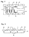
- Fig. 7 shows an embodiment of a statorless linear motor for two different vibration frequencies in a schematic side view.
- the first rotor 1 via a coil spring 23 with a first counterweight 24 and the second rotor 2 via a coil spring 25 with a second counterweight 26th connected.
- the coil springs 23 and 25 have a significantly higher spring constant than the leaf springs 9, of which for reasons of clarity in Fig. 7 only one is shown.
- Both the two runners 1 and 2 and the two counterweights 24 and 26 are suspended on the housing 22 by means of leaf springs 27, which are very weak, linearly movable, so that only very small vibrations are transmitted to the housing 22.
- the first rotor 1, the coil spring 23 and the first counterweight 24 and the second rotor 2, the coil spring 25 and the second counterweight 26 each form a vibration system that can be excited by applying a suitable voltage signal to the coil 5 to vibrational movements.
- the two vibration systems are designed so that they have different resonance frequencies, they can be selectively excited over two corresponding excitation frequencies in the voltage signal and thus the vibration amplitudes of the two vibration systems are each individually influenced. Accordingly, the vibration amplitudes of the shearing blades 10 and 11 and the shear films 14 and 15 can be influenced, which are coupled to the two vibration systems.
- This individual control via the voltage signal can be, for example, in the in Fig. 4 illustrated embodiment and apply in further embodiments of the invention.
- Fig. 8 shows one Fig. 3 corresponding block representation for the in Fig. 7 shown statorless linear motor.
- the first rotor 1 and the first counterweight 24 perform an opposite-phase oscillatory motion.
- the second runner 2 and the second counterweight 26 also perform an out-of-phase oscillation movement.
- the frequencies of these oscillatory movements usually correspond in each case to the resonant frequencies of the two oscillatory systems.
- the vibration amplitudes can be influenced individually via the control of the coil 5.
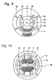
- the invention is not limited to electric razors and other small electrical appliances with linear motors, but can also be used in small electrical appliances with rotary motors, such as electric toothbrushes. This is in the Fig. 9 to 12 shown.
- Fig. 9 shows an embodiment of a statorless rotary motor in a schematic side view.
- the statorless rotary motor has similar functional components as the statorless linear motor. However, these functional components are the same modified that instead of a linear movement creates a rotational movement.
- the statorless ration motor on an outer rotor 28 which is rotatably suspended and consists of a ferrous material.
- the outer rotor 28 extends partially within the coil 5 without touching, however, so that the outer rotor 28 can be rotated relative to the stationarily arranged coil 5.
- an inner rotor 29 is arranged, which has a rotor core 30 made of a ferrous material and permanent magnets 6 attached thereto.
- the inner rotor 29 is also rotatably suspended, wherein the outer rotor 28 and the inner rotor 29 have a common axis of rotation 31.
- the rotary motor further comprises a series of coil springs 32 disposed between the outer rotor 28 and the inner rotor 29 and coil springs 33 disposed between the outer rotor 28 and a hollow cylindrical portion 34.
- the hollow cylindrical part 34 may be part of the housing 22 or suspended on figuratively not shown springs on the housing 22 and be connected for example in the case of an electric toothbrush with a Aufstecktechnikbürste.
- the rotary motor thus has two resonance frequencies.
- the control of the rotary motor the above explanations apply to the control of the linear motor in an analogous manner.
- the statorless rotary motor in a small electrical appliance instead of the two sets of coil springs 32 and 33 are preferably each one or more torsion springs used.
- Fig. 10 shows a further embodiment of the statorless rotary motor in a schematic side view. This embodiment is different from Fig. 9 essentially in that the coil 5 is a component of the inner rotor 29 and the permanent magnets 6 are components of the outer rotor 28.
- Fig. 11 shows one opposite Fig. 10
- Another modified embodiment for the statorless rotary motor in a schematic side view In this embodiment has been compared Fig. 10 only the arrangement of the permanent magnets 6 changed. The changed arrangement causes the outer rotor 28 and the inner rotor 29 are excited to linear oscillatory movements, which in the illustration of Fig. 11 run in the vertical direction.
- Fig. 12 shows an embodiment of a statorless rotary motor, which can perform a continuous rotary motion, in a schematic side view.
- the outer rotor 28 is equipped with the permanent magnets 6 and the inner rotor 29 has a plurality of coils 5. Between the outer rotor 28 and the hollow cylindrical part 34, the coil springs 33 are arranged. In order to allow a free rotation of the inner rotor 29, no coil springs 32 are attached to this.
- the rotational movement of the inner rotor 29 is generated by an alternating control of the coils 5 with a DC voltage, wherein the control can be carried out in a known manner by means of electronic switches.
- the DC voltage is superimposed on an AC voltage, so that the outer rotor 28 is excited to torsional vibrations, which are transmitted via the coil springs 33 to the housing 22.
- the drive is preferably carried out so that the AC voltage amplitude is not greater than the DC voltage.
- the spring strength of the coil springs 33 is dimensioned so that the desired oscillatory movement of the hollow cylindrical part 34 results.
- a vibratory motion is generated by the fact that the inner rotor 29 is formed with an imbalance.
- the amplitude of the oscillatory motion caused thereby can be influenced by the choice of the rotational frequency of the inner rotor 29 relative to the resonant frequency of the oscillatory motion.
Landscapes
- Engineering & Computer Science (AREA)
- Life Sciences & Earth Sciences (AREA)
- Forests & Forestry (AREA)
- Mechanical Engineering (AREA)
- Power Engineering (AREA)
- Dry Shavers And Clippers (AREA)
- Apparatuses For Generation Of Mechanical Vibrations (AREA)
- Brushes (AREA)
- Reciprocating, Oscillating Or Vibrating Motors (AREA)
Claims (17)
- Petit appareil électrique comprenant un moteur électrique sans stator permettant de produire au moins un mouvement oscillant, le moteur électrique sans stator présentant deux composants d'entraînement (1, 2, 28, 29) et l'un des composants d'entraînement (1, 2, 28, 29) étant relié à au moins un composant mobile par l'intermédiaire d'au moins un premier élément élastique (18, 19, 23, 25, 33) et pouvant être amené à un mouvement oscillant à l'aide d'un champ magnétique d'une bobine électrique (5), caractérisé en ce que les deux composants d'entraînement (1, 2, 28, 29) s'entraînent réciproquement et sont disposés de façon mobile dans le petit appareil électrique pour réaliser des mouvements oscillants en opposition de phase entre eux, et en ce que le moteur électrique sans stator ne possède aucun stator fixe.
- Petit appareil électrique selon la revendication 1, caractérisé en ce queles deux composants d'entraînement (1, 2, 28, 29) sont accouplés entre eux par au moins un second élément élastique (9, 32).
- Petit appareil électrique selon la revendication 2, caractérisé en ce que la rigidité de ressort du second élément élastique (9, 32) est supérieure à la rigidité du premier élément élastique (18, 19, 33).
- Petit appareil électrique selon l'une des revendications précédentes, caractérisé en ce que le composant mobile et le composant d'entraînement (1, 2, 28, 29), auquel le composant mobile est relié par l'intermédiaire du premier élément élastique (18, 19, 23, 25, 33), réalisent des mouvements oscillants en opposition de phase entre eux.
- Petit appareil électrique selon l'une des revendications précédentes, caractérisé en ce que le composant mobile est conçu sous la forme d'une première unité de travail (14, 15, 34).
- Petit appareil électrique selon l'une des revendications 1 à 4, caractérisé en ce que le composant mobile est conçu sous la forme d'une contre-masse (24, 26).
- Petit appareil électrique selon l'une des revendications précédentes, caractérisé en ce que le moteur électrique entraîne au moins une seconde unité de travail (10, 11).
- Petit appareil électrique selon la revendication 7, caractérisé en ce que la seconde unité de travail (10, 11) est relié de façon rigide à l'un des composants d'entraînement (1,2).
- Petit appareil électrique selon l'une des revendications 7 ou 8, caractérisé en ce que les deux unités d'entraînement (10, 11, 14, 15) réalisent des mouvements oscillants en opposition de phase entre eux.
- Petit appareil électrique selon l'une des revendications 7 à 9, caractérisé en ce que les deux unités d'entraînement (10, 11, 14, 15) réalisent des mouvements oscillants présentant une amplitude différente et/ou une fréquence différente.
- Petit appareil électrique selon l'une des revendications 7 à 10, caractérisé en ce que les amplitudes des mouvements oscillants des deux unités de travail (10, 11, 14, 15) peuvent être commandées individuellement par la bobine électrique (5).
- Petit appareil électrique selon l'une des revendications 7 à 11, caractérisé en ce que les deux unités de travail (10, 11, 14, 15) sont accouplées au même composant d'entraînement (1,2).
- Petit appareil électrique selon l'une des revendications précédentes, caractérisé en ce que le moteur électrique est conçu sous la forme d'un moteur linéaire oscillant.
- Petit appareil électrique selon la revendication 13, caractérisé en ce qu'il est conçu sous la forme d'un rasoir électrique.
- Petit appareil électrique selon l'une des revendications 1 à 12, caractérisé en ce que, le moteur électrique est conçu sous la forme d'un moteur rotatif oscillant.
- Petit appareil électrique selon la revendication 15, caractérisé en ce que le moteur rotatif oscillant réalise également un mouvement de rotation continu.
- Petit appareil électrique selon l'une des revendications 15 ou 16, caractérisé en ce qu'il est conçu sous la forme d'une brosse à dents électrique.
Applications Claiming Priority (2)
| Application Number | Priority Date | Filing Date | Title |
|---|---|---|---|
| DE10330978A DE10330978A1 (de) | 2003-07-09 | 2003-07-09 | Elektrisches Kleingerät mit einem Elektromotor zur Erzeugung einer oszillierenden Bewegung |
| PCT/EP2004/006199 WO2005006538A1 (fr) | 2003-07-09 | 2004-06-09 | Petit appareil electrique pourvu d'un moteur electrique et destine a produire un mouvement oscillant |
Publications (2)
| Publication Number | Publication Date |
|---|---|
| EP1641602A1 EP1641602A1 (fr) | 2006-04-05 |
| EP1641602B1 true EP1641602B1 (fr) | 2013-03-20 |
Family
ID=34041721
Family Applications (1)
| Application Number | Title | Priority Date | Filing Date |
|---|---|---|---|
| EP04739718A Expired - Lifetime EP1641602B1 (fr) | 2003-07-09 | 2004-06-09 | Petit appareil electrique pourvu d'un moteur electrique et destine a produire un mouvement oscillant |
Country Status (5)
| Country | Link |
|---|---|
| US (1) | US7288863B2 (fr) |
| EP (1) | EP1641602B1 (fr) |
| JP (1) | JP4890245B2 (fr) |
| DE (1) | DE10330978A1 (fr) |
| WO (1) | WO2005006538A1 (fr) |
Cited By (5)
| Publication number | Priority date | Publication date | Assignee | Title |
|---|---|---|---|---|
| USD766581S1 (en) | 2013-12-19 | 2016-09-20 | Colgate-Palmolive Company | Electric toothbrush handle |
| USD769626S1 (en) | 2013-12-19 | 2016-10-25 | Colgate-Palmolive Company | Refill head for electric toothbrush |
| USD776435S1 (en) | 2013-12-19 | 2017-01-17 | Colgate-Palmolive Company | Head portion of a toothbrush |
| USD790860S1 (en) | 2015-11-25 | 2017-07-04 | Colgate-Palmolive Company | Electric toothbrush brush head |
| USD794333S1 (en) | 2015-11-25 | 2017-08-15 | Colgate-Palmolive Company | Electric toothbrush brush head |
Families Citing this family (57)
| Publication number | Priority date | Publication date | Assignee | Title |
|---|---|---|---|---|
| JP4432840B2 (ja) * | 2005-06-21 | 2010-03-17 | パナソニック電工株式会社 | 振動型アクチュエータ |
| EP1912588B1 (fr) * | 2005-08-05 | 2016-10-12 | Koninklijke Philips N.V. | Systeme d'entrainement pendulaire pour appareils de soins personnels |
| JP5107922B2 (ja) | 2005-08-16 | 2012-12-26 | コーニンクレッカ フィリップス エレクトロニクス エヌ ヴィ | プログラマブル作動機能を有するパーソナルケア装置に対する共振アクチュエータ |
| EP1926447B1 (fr) * | 2005-09-08 | 2014-11-12 | Koninklijke Philips N.V. | Systeme d'actionnement pour appareil de soins personnels utilisant des organes d'entrainement lineaires |
| DE102005060537A1 (de) * | 2005-12-17 | 2007-06-21 | Braun Gmbh | Elektrischer Rasierapparat mit oszillierendem Scherkopf |
| DE102005060653A1 (de) * | 2005-12-19 | 2007-06-21 | Robert Bosch Gmbh | Vorrichtung zur Detektion eines Objekts |
| DE102006034050A1 (de) * | 2006-07-20 | 2008-01-24 | Braun Gmbh | Elektrischer Rasierapparat |
| EP2074397A4 (fr) * | 2006-09-22 | 2015-07-22 | Cornell Res Foundation Inc | Structure d'éléments mems couplés pour amplification de mouvement |
| EP2114637A1 (fr) * | 2007-02-01 | 2009-11-11 | Braun GmbH | Appareil d'épilation |
| US20080197720A1 (en) * | 2007-02-21 | 2008-08-21 | Fuji Electric Systems Co., Ltd. | Vibrating-type motor |
| JP5277580B2 (ja) * | 2007-07-27 | 2013-08-28 | オムロンヘルスケア株式会社 | 電動歯ブラシ |
| DE102007050379A1 (de) | 2007-10-22 | 2009-04-23 | Braun Gmbh | Haartrimmer |
| DE102007050381A1 (de) * | 2007-10-22 | 2009-04-23 | Braun Gmbh | Haarentfernungsgerät |
| EP2296850B1 (fr) * | 2008-05-27 | 2012-09-26 | Koninklijke Philips Electronics N.V. | Appareil domestique comprenant des moyens pour générer de l'énergie électrique dans une unité à action fonctionnelle |
| DE102008031132A1 (de) * | 2008-07-01 | 2010-01-07 | Braun Gmbh | Elektrisches Kleingerät zum Entfernen von Haaren |
| US9072576B2 (en) * | 2008-12-08 | 2015-07-07 | Sunstar Inc. | Linear actuator |
| EP2262084A1 (fr) | 2009-06-12 | 2010-12-15 | Braun GmbH | Moteur électrique pour un petit appareil électrique |
| GB2471913B (en) * | 2009-07-17 | 2012-02-01 | Samsung Electro Mech | Horizontal linear vibrator |
| KR101084860B1 (ko) * | 2009-07-22 | 2011-11-21 | 삼성전기주식회사 | 수평 리니어 진동자 |
| JP5712362B2 (ja) * | 2009-09-25 | 2015-05-07 | パナソニックIpマネジメント株式会社 | 電気かみそり |
| JP2012016492A (ja) * | 2010-07-08 | 2012-01-26 | Panasonic Electric Works Co Ltd | 往復式電気かみそり |
| EP2410641A1 (fr) | 2010-07-23 | 2012-01-25 | Braun GmbH | Moteur électrique linéaire |
| US9427294B2 (en) | 2010-08-19 | 2016-08-30 | Braun Gmbh | Method for operating an electric appliance and electric appliance |
| KR101796094B1 (ko) * | 2010-09-01 | 2017-11-09 | 주식회사 이엠텍 | 수평 진동 모터 |
| US20120146557A1 (en) * | 2010-12-09 | 2012-06-14 | Korea Advanced Institute Of Science And Technology | Vibration generating module, actuator using the same, handheld device, method for generating vibration and recording medium thereof |
| JP5763425B2 (ja) * | 2011-06-03 | 2015-08-12 | 株式会社 イマジナホールディングス | 振動発生装置 |
| ES2534822T3 (es) | 2011-07-25 | 2015-04-29 | Braun Gmbh | Dispositivo de higiene bucodental |
| DK2550937T3 (da) | 2011-07-25 | 2014-05-19 | Braun Gmbh | Magnetforbindelse mellem et tandbørstehåndtag og et børstehoved |
| EP2737619B1 (fr) | 2011-07-25 | 2017-08-23 | Braun GmbH | Dispositifs d'hygiène orale avec moteurs linéaires électriques à polymère |
| ES2693620T3 (es) * | 2012-07-13 | 2018-12-13 | Braun Gmbh | Motor lineal y dispositivo eléctrico con motor lineal |
| US9148046B2 (en) * | 2012-08-01 | 2015-09-29 | Beijing University Of Technology | Method and device for torque generation based on electromagnetic effect |
| CN103622758A (zh) * | 2013-11-18 | 2014-03-12 | 王�锋 | 一种口含式震动清洁牙刷系统 |
| CN107107353B (zh) * | 2014-12-23 | 2020-02-14 | 博朗有限公司 | 线性马达及其支撑件 |
| US20160226364A1 (en) * | 2015-01-30 | 2016-08-04 | Sunbeam Products, Inc. | Electric Hair Clipper/Trimmer |
| CN204810103U (zh) * | 2015-07-08 | 2015-11-25 | 瑞声光电科技(常州)有限公司 | 振动电机 |
| US9966825B2 (en) * | 2015-09-18 | 2018-05-08 | Apple Inc. | Haptic actuator including slidably coupled masses including coils and related methods |
| CN105226908B (zh) * | 2015-10-20 | 2019-03-22 | 瑞声光电科技(常州)有限公司 | 直线振动电机 |
| JP6070807B2 (ja) * | 2015-11-19 | 2017-02-01 | ミツミ電機株式会社 | アクチュエータ及び電動理美容器具 |
| CN105598797B (zh) * | 2016-02-19 | 2018-09-07 | 胡建坤 | 电动磨削器 |
| EP3509536B1 (fr) | 2016-09-12 | 2021-02-17 | Koninklijke Philips N.V. | Ensemble de transmission pour dispositif de soin personnel |
| WO2018165757A1 (fr) | 2017-03-14 | 2018-09-20 | Martin Niles | Dispositifs de coupe de poils du dos et de poils corporels, et procédés d'utilisation associés |
| US10975526B2 (en) | 2017-04-18 | 2021-04-13 | Harsco Technologies LLC | Linear actuator for rail applications |
| CN110719762B (zh) | 2017-05-09 | 2022-06-03 | 皇家飞利浦有限公司 | 个人护理清洁设备和振动消除悬架 |
| CN208589887U (zh) * | 2018-08-03 | 2019-03-08 | 瑞声科技(南京)有限公司 | 振动电机 |
| US11413212B2 (en) | 2019-01-30 | 2022-08-16 | L'oreal | Energy regenerating end effector, and associated systems and methods |
| USD950729S1 (en) | 2019-09-30 | 2022-05-03 | Water Pik, Inc. | Toothbrush drive train |
| US11864965B2 (en) | 2019-09-30 | 2024-01-09 | Water Pik, Inc. | Electric toothbrush |
| JP7533871B2 (ja) * | 2020-01-15 | 2024-08-14 | ミネベアミツミ株式会社 | 振動アクチュエーター及び電子機器 |
| US20210257896A1 (en) * | 2020-02-17 | 2021-08-19 | Dan Haronian | Movement and Vibration energy harvesting |
| JP7504624B2 (ja) * | 2020-02-28 | 2024-06-24 | キヤノン株式会社 | 発電素子、及び発電素子を用いた装置 |
| US12352257B2 (en) | 2020-03-31 | 2025-07-08 | Minebea Mitsumi Inc. | Pump and air supply device |
| JPWO2022185818A1 (fr) * | 2021-03-02 | 2022-09-09 | ||
| US12278537B2 (en) * | 2021-05-05 | 2025-04-15 | Enervibe Ltd. | Electromagnetic vibration and energy harvester |
| EP4145697A1 (fr) | 2021-09-01 | 2023-03-08 | Braun GmbH | Unité de moteur et dispositif de soins personnels comprenant une unité de moteur |
| US11936269B2 (en) * | 2021-09-22 | 2024-03-19 | Apple Inc. | Haptic engine based on angular resonant actuator with pivot axis and mass center that differ |
| CN115816515B (zh) * | 2022-12-26 | 2026-04-21 | 深圳术叶创新科技有限公司 | 电动剃须刀 |
| EP4484084B1 (fr) | 2023-06-29 | 2026-01-21 | Braun GmbH | Tondeuse à cheveux |
Family Cites Families (24)
| Publication number | Priority date | Publication date | Assignee | Title |
|---|---|---|---|---|
| USRE25934E (en) * | 1965-12-07 | Electromagnetically-controlled compressing and pumping devices | ||
| CH265598A (de) * | 1946-01-23 | 1949-12-15 | Odstrcil Borivoj | Trockenrasierapparat. |
| BE563029A (fr) * | 1957-01-25 | |||
| NL136196C (fr) * | 1960-09-29 | |||
| GB1028215A (en) * | 1963-02-02 | 1966-05-04 | Morphy Richards Cray Ltd | Improvements relating to vibrator motors for electric dry shavers and other electro-mechanical devices |
| DE1757384A1 (de) * | 1968-05-02 | 1971-04-15 | Braun Ag | Schwingankerantrieb fuer elektrische Zahnbuerste |
| US3525887A (en) * | 1968-08-16 | 1970-08-25 | Benjamin B D Ewart Jr | Motor with linear reciprocating output |
| FR2179653B1 (fr) * | 1972-04-13 | 1974-07-26 | Crouzet Sa | |
| US3729691A (en) * | 1972-06-16 | 1973-04-24 | Verta Tronics Inc | Electro-mechanical oscillator of electrodynamical and electromagnetic types |
| US3906263A (en) * | 1974-05-23 | 1975-09-16 | Sperry Rand Corp | Vibrator motor in hand-held electric appliance |
| US4169234A (en) * | 1975-02-14 | 1979-09-25 | Yonkers Edward H | Reciprocating motor |
| CH646554A5 (de) * | 1979-07-11 | 1984-11-30 | Lpa Les Produits Associes | Wechselstrom-kleinmotor mit pendelndem dauermagnetischen laeufer. |
| JPS6010524Y2 (ja) * | 1981-06-30 | 1985-04-10 | 松下電工株式会社 | 往復式電気かみそり |
| JPS5874478A (ja) * | 1981-10-26 | 1983-05-04 | 三菱電機株式会社 | 展望用エレベ−タ |
| GB8814777D0 (en) * | 1988-06-22 | 1988-07-27 | Renishaw Plc | Controlled linear motor |
| US5189751A (en) * | 1991-03-21 | 1993-03-02 | Gemtech, Inc. | Vibrating toothbrush using a magnetic driver |
| WO1995026261A1 (fr) * | 1994-03-28 | 1995-10-05 | Matsushita Electric Works, Ltd. | Rasoir a sec a mouvement alternatif |
| JP3382007B2 (ja) * | 1994-03-28 | 2003-03-04 | 松下電工株式会社 | 往復式電気かみそり |
| US5833440A (en) * | 1995-02-10 | 1998-11-10 | Berling; James T. | Linear motor arrangement for a reciprocating pump system |
| JP3266757B2 (ja) * | 1995-05-26 | 2002-03-18 | 松下電工株式会社 | 振動型リニアアクチュエータ |
| JP3382061B2 (ja) * | 1995-05-31 | 2003-03-04 | 松下電工株式会社 | リニア振動モータ |
| CN1079315C (zh) * | 1996-03-26 | 2002-02-20 | 松下电工株式会社 | 往复式电动剃刀 |
| US6873067B2 (en) * | 2000-09-29 | 2005-03-29 | Matsushita Electric Works, Ltd. | Linear oscillator |
| JP3915607B2 (ja) * | 2002-06-17 | 2007-05-16 | 松下電工株式会社 | 振動型リニアアクチュエータとこれを用いた電気かみそり |
-
2003
- 2003-07-09 DE DE10330978A patent/DE10330978A1/de not_active Withdrawn
-
2004
- 2004-06-09 JP JP2006517999A patent/JP4890245B2/ja not_active Expired - Lifetime
- 2004-06-09 EP EP04739718A patent/EP1641602B1/fr not_active Expired - Lifetime
- 2004-06-09 WO PCT/EP2004/006199 patent/WO2005006538A1/fr not_active Ceased
-
2006
- 2006-01-09 US US11/328,329 patent/US7288863B2/en not_active Expired - Lifetime
Cited By (6)
| Publication number | Priority date | Publication date | Assignee | Title |
|---|---|---|---|---|
| USD766581S1 (en) | 2013-12-19 | 2016-09-20 | Colgate-Palmolive Company | Electric toothbrush handle |
| USD769626S1 (en) | 2013-12-19 | 2016-10-25 | Colgate-Palmolive Company | Refill head for electric toothbrush |
| USD776435S1 (en) | 2013-12-19 | 2017-01-17 | Colgate-Palmolive Company | Head portion of a toothbrush |
| USD812911S1 (en) | 2013-12-19 | 2018-03-20 | Colgate-Palmolive Company | Head portion of a toothbrush |
| USD790860S1 (en) | 2015-11-25 | 2017-07-04 | Colgate-Palmolive Company | Electric toothbrush brush head |
| USD794333S1 (en) | 2015-11-25 | 2017-08-15 | Colgate-Palmolive Company | Electric toothbrush brush head |
Also Published As
| Publication number | Publication date |
|---|---|
| US20060175909A1 (en) | 2006-08-10 |
| US7288863B2 (en) | 2007-10-30 |
| EP1641602A1 (fr) | 2006-04-05 |
| WO2005006538A8 (fr) | 2005-04-21 |
| WO2005006538A1 (fr) | 2005-01-20 |
| DE10330978A1 (de) | 2005-02-10 |
| JP4890245B2 (ja) | 2012-03-07 |
| JP2007506539A (ja) | 2007-03-22 |
Similar Documents
| Publication | Publication Date | Title |
|---|---|---|
| EP1641602B1 (fr) | Petit appareil electrique pourvu d'un moteur electrique et destine a produire un mouvement oscillant | |
| EP1509368B1 (fr) | Dispositif de commande concu pour generer un mouvement d'oscillation pour un petit appareil electrique | |
| EP1687887B1 (fr) | Moteur electrique pour petit appareil electrique | |
| EP1539437B1 (fr) | Petit electromenager comprenant un dispositif d'entrainement destine a produire un mouvement oscillatoire | |
| EP2043828B1 (fr) | Rasoir électrique | |
| EP0313130B1 (fr) | Moteur électrique rotatif ou linéaire ayant son rotor commandé par des vibrations ultrasoniques | |
| WO2008077454A1 (fr) | Dispositif d'entraînement servant à entraîner un élément de brossage de brosse à dents électrique | |
| EP1108283A1 (fr) | Actionneur electromagnetique dote d'un systeme ressort-masse oscillant | |
| EP2262085A1 (fr) | Petit appareil électrique et unité d'entraînement électro-motorisée pour un petit appareil électrique | |
| EP1539439B1 (fr) | Petit electromenager comprenant un dispositif d'entrainement destine a produire un mouvement oscillatoire | |
| EP3801855B1 (fr) | Dispositif de mélange de liquides et de solides avec des liquides par vibration | |
| DE10242094B4 (de) | Antriebseinrichtung zum Erzeugen einer oszillierenden Bewegung für ein elektrisches Kleingerät | |
| DE102005060537A1 (de) | Elektrischer Rasierapparat mit oszillierendem Scherkopf | |
| DE69401742T2 (de) | Epizykloidische Schwingungsvorrichtung | |
| EP1539438B1 (fr) | Dispositif d'entrainement destine a produire un mouvement oscillatoire pour un petit electromenager | |
| EP1642380B1 (fr) | Procede de commande d'un moteur electrique pourvu de plusieurs composants oscillants | |
| DE3417807C2 (de) | Trockenrasier- bzw. Haarschneidegerät, das mittels eines zweipoligen Einphasensynchronmotors angetrieben wird | |
| DE947350C (de) | Anordnung zur Herstellung von Schweissverbindungen | |
| DE964998C (de) | Anordnung zur Erzeugung mechanischer Schwingbewegungen eines Koerpers auf in sich geschlossenen, z.B. geradlinigen oder kreisfoermigen Schwingungsbahnen | |
| DE102015103097A1 (de) | Handgeführtes Oszillationswerkzeug | |
| DE4117225A1 (de) | Haushaltsvibrationsgeraet, insbesondere trockenrasier- oder haarschneidegeraet | |
| DE4117226A1 (de) | Haushaltsvibrationsgeraet mit einem vibrationsteil und einstellbarer eigenfrequenz | |
| DESC013028MA (fr) |
Legal Events
| Date | Code | Title | Description |
|---|---|---|---|
| PUAI | Public reference made under article 153(3) epc to a published international application that has entered the european phase |
Free format text: ORIGINAL CODE: 0009012 |
|
| 17P | Request for examination filed |
Effective date: 20051201 |
|
| AK | Designated contracting states |
Kind code of ref document: A1 Designated state(s): AT BE BG CH CY CZ DE DK EE ES FI FR GB GR HU IE IT LI LU MC NL PL PT RO SE SI SK TR |
|
| DAX | Request for extension of the european patent (deleted) | ||
| 17Q | First examination report despatched |
Effective date: 20091023 |
|
| GRAP | Despatch of communication of intention to grant a patent |
Free format text: ORIGINAL CODE: EPIDOSNIGR1 |
|
| GRAS | Grant fee paid |
Free format text: ORIGINAL CODE: EPIDOSNIGR3 |
|
| GRAA | (expected) grant |
Free format text: ORIGINAL CODE: 0009210 |
|
| AK | Designated contracting states |
Kind code of ref document: B1 Designated state(s): AT BE BG CH CY CZ DE DK EE ES FI FR GB GR HU IE IT LI LU MC NL PL PT RO SE SI SK TR |
|
| REG | Reference to a national code |
Ref country code: GB Ref legal event code: FG4D Free format text: NOT ENGLISH |
|
| REG | Reference to a national code |
Ref country code: CH Ref legal event code: EP Ref country code: CH Ref legal event code: NV Representative=s name: BOHEST AG, CH |
|
| REG | Reference to a national code |
Ref country code: IE Ref legal event code: FG4D Free format text: LANGUAGE OF EP DOCUMENT: GERMAN |
|
| REG | Reference to a national code |
Ref country code: AT Ref legal event code: REF Ref document number: 601775 Country of ref document: AT Kind code of ref document: T Effective date: 20130415 |
|
| REG | Reference to a national code |
Ref country code: DE Ref legal event code: R096 Ref document number: 502004014073 Country of ref document: DE Effective date: 20130516 |
|
| PG25 | Lapsed in a contracting state [announced via postgrant information from national office to epo] |
Ref country code: BG Free format text: LAPSE BECAUSE OF FAILURE TO SUBMIT A TRANSLATION OF THE DESCRIPTION OR TO PAY THE FEE WITHIN THE PRESCRIBED TIME-LIMIT Effective date: 20130620 Ref country code: ES Free format text: LAPSE BECAUSE OF FAILURE TO SUBMIT A TRANSLATION OF THE DESCRIPTION OR TO PAY THE FEE WITHIN THE PRESCRIBED TIME-LIMIT Effective date: 20130701 Ref country code: SE Free format text: LAPSE BECAUSE OF FAILURE TO SUBMIT A TRANSLATION OF THE DESCRIPTION OR TO PAY THE FEE WITHIN THE PRESCRIBED TIME-LIMIT Effective date: 20130320 |
|
| REG | Reference to a national code |
Ref country code: NL Ref legal event code: T3 |
|
| PG25 | Lapsed in a contracting state [announced via postgrant information from national office to epo] |
Ref country code: GR Free format text: LAPSE BECAUSE OF FAILURE TO SUBMIT A TRANSLATION OF THE DESCRIPTION OR TO PAY THE FEE WITHIN THE PRESCRIBED TIME-LIMIT Effective date: 20130621 Ref country code: SI Free format text: LAPSE BECAUSE OF FAILURE TO SUBMIT A TRANSLATION OF THE DESCRIPTION OR TO PAY THE FEE WITHIN THE PRESCRIBED TIME-LIMIT Effective date: 20130320 Ref country code: FI Free format text: LAPSE BECAUSE OF FAILURE TO SUBMIT A TRANSLATION OF THE DESCRIPTION OR TO PAY THE FEE WITHIN THE PRESCRIBED TIME-LIMIT Effective date: 20130320 |
|
| PG25 | Lapsed in a contracting state [announced via postgrant information from national office to epo] |
Ref country code: SK Free format text: LAPSE BECAUSE OF FAILURE TO SUBMIT A TRANSLATION OF THE DESCRIPTION OR TO PAY THE FEE WITHIN THE PRESCRIBED TIME-LIMIT Effective date: 20130320 Ref country code: CZ Free format text: LAPSE BECAUSE OF FAILURE TO SUBMIT A TRANSLATION OF THE DESCRIPTION OR TO PAY THE FEE WITHIN THE PRESCRIBED TIME-LIMIT Effective date: 20130320 Ref country code: EE Free format text: LAPSE BECAUSE OF FAILURE TO SUBMIT A TRANSLATION OF THE DESCRIPTION OR TO PAY THE FEE WITHIN THE PRESCRIBED TIME-LIMIT Effective date: 20130320 Ref country code: RO Free format text: LAPSE BECAUSE OF FAILURE TO SUBMIT A TRANSLATION OF THE DESCRIPTION OR TO PAY THE FEE WITHIN THE PRESCRIBED TIME-LIMIT Effective date: 20130320 Ref country code: PT Free format text: LAPSE BECAUSE OF FAILURE TO SUBMIT A TRANSLATION OF THE DESCRIPTION OR TO PAY THE FEE WITHIN THE PRESCRIBED TIME-LIMIT Effective date: 20130722 |
|
| PG25 | Lapsed in a contracting state [announced via postgrant information from national office to epo] |
Ref country code: PL Free format text: LAPSE BECAUSE OF FAILURE TO SUBMIT A TRANSLATION OF THE DESCRIPTION OR TO PAY THE FEE WITHIN THE PRESCRIBED TIME-LIMIT Effective date: 20130320 Ref country code: CY Free format text: LAPSE BECAUSE OF FAILURE TO SUBMIT A TRANSLATION OF THE DESCRIPTION OR TO PAY THE FEE WITHIN THE PRESCRIBED TIME-LIMIT Effective date: 20130320 |
|
| PLBE | No opposition filed within time limit |
Free format text: ORIGINAL CODE: 0009261 |
|
| STAA | Information on the status of an ep patent application or granted ep patent |
Free format text: STATUS: NO OPPOSITION FILED WITHIN TIME LIMIT |
|
| PG25 | Lapsed in a contracting state [announced via postgrant information from national office to epo] |
Ref country code: DK Free format text: LAPSE BECAUSE OF FAILURE TO SUBMIT A TRANSLATION OF THE DESCRIPTION OR TO PAY THE FEE WITHIN THE PRESCRIBED TIME-LIMIT Effective date: 20130320 Ref country code: MC Free format text: LAPSE BECAUSE OF FAILURE TO SUBMIT A TRANSLATION OF THE DESCRIPTION OR TO PAY THE FEE WITHIN THE PRESCRIBED TIME-LIMIT Effective date: 20130320 |
|
| 26N | No opposition filed |
Effective date: 20140102 |
|
| REG | Reference to a national code |
Ref country code: IE Ref legal event code: MM4A |
|
| REG | Reference to a national code |
Ref country code: DE Ref legal event code: R097 Ref document number: 502004014073 Country of ref document: DE Effective date: 20140102 |
|
| PG25 | Lapsed in a contracting state [announced via postgrant information from national office to epo] |
Ref country code: IE Free format text: LAPSE BECAUSE OF NON-PAYMENT OF DUE FEES Effective date: 20130609 |
|
| PG25 | Lapsed in a contracting state [announced via postgrant information from national office to epo] |
Ref country code: TR Free format text: LAPSE BECAUSE OF FAILURE TO SUBMIT A TRANSLATION OF THE DESCRIPTION OR TO PAY THE FEE WITHIN THE PRESCRIBED TIME-LIMIT Effective date: 20130320 |
|
| PG25 | Lapsed in a contracting state [announced via postgrant information from national office to epo] |
Ref country code: LU Free format text: LAPSE BECAUSE OF NON-PAYMENT OF DUE FEES Effective date: 20130609 Ref country code: HU Free format text: LAPSE BECAUSE OF FAILURE TO SUBMIT A TRANSLATION OF THE DESCRIPTION OR TO PAY THE FEE WITHIN THE PRESCRIBED TIME-LIMIT; INVALID AB INITIO Effective date: 20040609 |
|
| REG | Reference to a national code |
Ref country code: FR Ref legal event code: PLFP Year of fee payment: 13 |
|
| REG | Reference to a national code |
Ref country code: FR Ref legal event code: PLFP Year of fee payment: 14 |
|
| PGFP | Annual fee paid to national office [announced via postgrant information from national office to epo] |
Ref country code: BE Payment date: 20170515 Year of fee payment: 14 Ref country code: AT Payment date: 20170525 Year of fee payment: 14 Ref country code: IT Payment date: 20170619 Year of fee payment: 14 |
|
| REG | Reference to a national code |
Ref country code: FR Ref legal event code: PLFP Year of fee payment: 15 |
|
| REG | Reference to a national code |
Ref country code: CH Ref legal event code: PL |
|
| REG | Reference to a national code |
Ref country code: AT Ref legal event code: MM01 Ref document number: 601775 Country of ref document: AT Kind code of ref document: T Effective date: 20180609 |
|
| REG | Reference to a national code |
Ref country code: BE Ref legal event code: MM Effective date: 20180630 |
|
| PG25 | Lapsed in a contracting state [announced via postgrant information from national office to epo] |
Ref country code: CH Free format text: LAPSE BECAUSE OF NON-PAYMENT OF DUE FEES Effective date: 20180630 Ref country code: AT Free format text: LAPSE BECAUSE OF NON-PAYMENT OF DUE FEES Effective date: 20180609 Ref country code: LI Free format text: LAPSE BECAUSE OF NON-PAYMENT OF DUE FEES Effective date: 20180630 Ref country code: IT Free format text: LAPSE BECAUSE OF NON-PAYMENT OF DUE FEES Effective date: 20180609 |
|
| PG25 | Lapsed in a contracting state [announced via postgrant information from national office to epo] |
Ref country code: BE Free format text: LAPSE BECAUSE OF NON-PAYMENT OF DUE FEES Effective date: 20180630 |
|
| P01 | Opt-out of the competence of the unified patent court (upc) registered |
Effective date: 20230430 |
|
| PGFP | Annual fee paid to national office [announced via postgrant information from national office to epo] |
Ref country code: NL Payment date: 20230515 Year of fee payment: 20 Ref country code: FR Payment date: 20230510 Year of fee payment: 20 Ref country code: DE Payment date: 20230502 Year of fee payment: 20 |
|
| PGFP | Annual fee paid to national office [announced via postgrant information from national office to epo] |
Ref country code: GB Payment date: 20230504 Year of fee payment: 20 |
|
| REG | Reference to a national code |
Ref country code: DE Ref legal event code: R071 Ref document number: 502004014073 Country of ref document: DE |
|
| REG | Reference to a national code |
Ref country code: NL Ref legal event code: MK Effective date: 20240608 |
|
| PG25 | Lapsed in a contracting state [announced via postgrant information from national office to epo] |
Ref country code: GB Free format text: LAPSE BECAUSE OF EXPIRATION OF PROTECTION Effective date: 20240608 |
|
| PG25 | Lapsed in a contracting state [announced via postgrant information from national office to epo] |
Ref country code: GB Free format text: LAPSE BECAUSE OF EXPIRATION OF PROTECTION Effective date: 20240608 |