EP1642018B1 - Systeme de soupape et procede pour injecter du carburant sous forme gazeuse - Google Patents
Systeme de soupape et procede pour injecter du carburant sous forme gazeuse Download PDFInfo
- Publication number
- EP1642018B1 EP1642018B1 EP04739663A EP04739663A EP1642018B1 EP 1642018 B1 EP1642018 B1 EP 1642018B1 EP 04739663 A EP04739663 A EP 04739663A EP 04739663 A EP04739663 A EP 04739663A EP 1642018 B1 EP1642018 B1 EP 1642018B1
- Authority
- EP
- European Patent Office
- Prior art keywords
- valve
- actuator
- transmission device
- injection
- levers
- Prior art date
- Legal status (The legal status is an assumption and is not a legal conclusion. Google has not performed a legal analysis and makes no representation as to the accuracy of the status listed.)
- Expired - Lifetime
Links
- 239000000446 fuel Substances 0.000 title claims abstract description 46
- 238000000034 method Methods 0.000 title claims abstract description 17
- 238000002347 injection Methods 0.000 claims description 50
- 239000007924 injection Substances 0.000 claims description 50
- 230000005540 biological transmission Effects 0.000 claims description 42
- 238000002485 combustion reaction Methods 0.000 claims description 26
- 230000004913 activation Effects 0.000 claims description 7
- 230000008569 process Effects 0.000 claims description 6
- 239000000919 ceramic Substances 0.000 claims description 5
- 238000001514 detection method Methods 0.000 claims description 4
- 239000012528 membrane Substances 0.000 claims description 4
- 238000007667 floating Methods 0.000 claims description 3
- 238000012545 processing Methods 0.000 claims description 3
- 230000001105 regulatory effect Effects 0.000 claims description 3
- 239000002131 composite material Substances 0.000 claims description 2
- 230000001276 controlling effect Effects 0.000 claims 2
- 238000011156 evaluation Methods 0.000 claims 1
- 239000002184 metal Substances 0.000 claims 1
- 229910001092 metal group alloy Inorganic materials 0.000 claims 1
- 230000004044 response Effects 0.000 abstract description 15
- 238000006243 chemical reaction Methods 0.000 abstract 1
- 238000013519 translation Methods 0.000 description 22
- 238000010276 construction Methods 0.000 description 6
- 238000007493 shaping process Methods 0.000 description 6
- 230000001419 dependent effect Effects 0.000 description 4
- 238000013461 design Methods 0.000 description 4
- 239000007789 gas Substances 0.000 description 4
- 229910052739 hydrogen Inorganic materials 0.000 description 4
- 239000001257 hydrogen Substances 0.000 description 4
- VNWKTOKETHGBQD-UHFFFAOYSA-N methane Chemical compound C VNWKTOKETHGBQD-UHFFFAOYSA-N 0.000 description 4
- 230000008901 benefit Effects 0.000 description 3
- 239000000314 lubricant Substances 0.000 description 3
- UFHFLCQGNIYNRP-UHFFFAOYSA-N Hydrogen Chemical compound [H][H] UFHFLCQGNIYNRP-UHFFFAOYSA-N 0.000 description 2
- 150000002431 hydrogen Chemical class 0.000 description 2
- 239000007788 liquid Substances 0.000 description 2
- 239000003345 natural gas Substances 0.000 description 2
- 238000012935 Averaging Methods 0.000 description 1
- 230000005355 Hall effect Effects 0.000 description 1
- 229910001069 Ti alloy Inorganic materials 0.000 description 1
- 230000009471 action Effects 0.000 description 1
- 230000006978 adaptation Effects 0.000 description 1
- 239000000956 alloy Substances 0.000 description 1
- 229910045601 alloy Inorganic materials 0.000 description 1
- 230000009286 beneficial effect Effects 0.000 description 1
- 230000015572 biosynthetic process Effects 0.000 description 1
- 239000004918 carbon fiber reinforced polymer Substances 0.000 description 1
- 239000011248 coating agent Substances 0.000 description 1
- 238000000576 coating method Methods 0.000 description 1
- 230000006835 compression Effects 0.000 description 1
- 238000007906 compression Methods 0.000 description 1
- 238000011161 development Methods 0.000 description 1
- 230000018109 developmental process Effects 0.000 description 1
- 238000006073 displacement reaction Methods 0.000 description 1
- 230000000694 effects Effects 0.000 description 1
- 229920001971 elastomer Polymers 0.000 description 1
- 239000000806 elastomer Substances 0.000 description 1
- 230000005672 electromagnetic field Effects 0.000 description 1
- 238000007689 inspection Methods 0.000 description 1
- 239000000463 material Substances 0.000 description 1
- 239000000203 mixture Substances 0.000 description 1
- 238000005070 sampling Methods 0.000 description 1
- 238000007789 sealing Methods 0.000 description 1
- 239000007787 solid Substances 0.000 description 1
- 125000006850 spacer group Chemical group 0.000 description 1
Images


Classifications
-
- F—MECHANICAL ENGINEERING; LIGHTING; HEATING; WEAPONS; BLASTING
- F02—COMBUSTION ENGINES; HOT-GAS OR COMBUSTION-PRODUCT ENGINE PLANTS
- F02M—SUPPLYING COMBUSTION ENGINES IN GENERAL WITH COMBUSTIBLE MIXTURES OR CONSTITUENTS THEREOF
- F02M51/00—Fuel-injection apparatus characterised by being operated electrically
- F02M51/06—Injectors peculiar thereto with means directly operating the valve needle
- F02M51/0603—Injectors peculiar thereto with means directly operating the valve needle using piezoelectric or magnetostrictive operating means
-
- F—MECHANICAL ENGINEERING; LIGHTING; HEATING; WEAPONS; BLASTING
- F02—COMBUSTION ENGINES; HOT-GAS OR COMBUSTION-PRODUCT ENGINE PLANTS
- F02M—SUPPLYING COMBUSTION ENGINES IN GENERAL WITH COMBUSTIBLE MIXTURES OR CONSTITUENTS THEREOF
- F02M21/00—Apparatus for supplying engines with non-liquid fuels, e.g. gaseous fuels stored in liquid form
- F02M21/02—Apparatus for supplying engines with non-liquid fuels, e.g. gaseous fuels stored in liquid form for gaseous fuels
- F02M21/0218—Details on the gaseous fuel supply system, e.g. tanks, valves, pipes, pumps, rails, injectors or mixers
- F02M21/0248—Injectors
- F02M21/0251—Details of actuators therefor
- F02M21/0254—Electric actuators, e.g. solenoid or piezoelectric
-
- F—MECHANICAL ENGINEERING; LIGHTING; HEATING; WEAPONS; BLASTING
- F02—COMBUSTION ENGINES; HOT-GAS OR COMBUSTION-PRODUCT ENGINE PLANTS
- F02M—SUPPLYING COMBUSTION ENGINES IN GENERAL WITH COMBUSTIBLE MIXTURES OR CONSTITUENTS THEREOF
- F02M21/00—Apparatus for supplying engines with non-liquid fuels, e.g. gaseous fuels stored in liquid form
- F02M21/02—Apparatus for supplying engines with non-liquid fuels, e.g. gaseous fuels stored in liquid form for gaseous fuels
- F02M21/0218—Details on the gaseous fuel supply system, e.g. tanks, valves, pipes, pumps, rails, injectors or mixers
- F02M21/0248—Injectors
- F02M21/0257—Details of the valve closing elements, e.g. valve seats, stems or arrangement of flow passages
- F02M21/026—Lift valves, i.e. stem operated valves
- F02M21/0263—Inwardly opening single or multi nozzle valves, e.g. needle valves
-
- F—MECHANICAL ENGINEERING; LIGHTING; HEATING; WEAPONS; BLASTING
- F02—COMBUSTION ENGINES; HOT-GAS OR COMBUSTION-PRODUCT ENGINE PLANTS
- F02M—SUPPLYING COMBUSTION ENGINES IN GENERAL WITH COMBUSTIBLE MIXTURES OR CONSTITUENTS THEREOF
- F02M21/00—Apparatus for supplying engines with non-liquid fuels, e.g. gaseous fuels stored in liquid form
- F02M21/02—Apparatus for supplying engines with non-liquid fuels, e.g. gaseous fuels stored in liquid form for gaseous fuels
- F02M21/0218—Details on the gaseous fuel supply system, e.g. tanks, valves, pipes, pumps, rails, injectors or mixers
- F02M21/0248—Injectors
- F02M21/0257—Details of the valve closing elements, e.g. valve seats, stems or arrangement of flow passages
- F02M21/026—Lift valves, i.e. stem operated valves
- F02M21/0269—Outwardly opening valves, e.g. poppet valves
-
- F—MECHANICAL ENGINEERING; LIGHTING; HEATING; WEAPONS; BLASTING
- F02—COMBUSTION ENGINES; HOT-GAS OR COMBUSTION-PRODUCT ENGINE PLANTS
- F02M—SUPPLYING COMBUSTION ENGINES IN GENERAL WITH COMBUSTIBLE MIXTURES OR CONSTITUENTS THEREOF
- F02M21/00—Apparatus for supplying engines with non-liquid fuels, e.g. gaseous fuels stored in liquid form
- F02M21/02—Apparatus for supplying engines with non-liquid fuels, e.g. gaseous fuels stored in liquid form for gaseous fuels
- F02M21/0218—Details on the gaseous fuel supply system, e.g. tanks, valves, pipes, pumps, rails, injectors or mixers
- F02M21/0248—Injectors
- F02M21/0275—Injectors for in-cylinder direct injection, e.g. injector combined with spark plug
-
- F—MECHANICAL ENGINEERING; LIGHTING; HEATING; WEAPONS; BLASTING
- F02—COMBUSTION ENGINES; HOT-GAS OR COMBUSTION-PRODUCT ENGINE PLANTS
- F02M—SUPPLYING COMBUSTION ENGINES IN GENERAL WITH COMBUSTIBLE MIXTURES OR CONSTITUENTS THEREOF
- F02M61/00—Fuel-injectors not provided for in groups F02M39/00 - F02M57/00 or F02M67/00
- F02M61/04—Fuel-injectors not provided for in groups F02M39/00 - F02M57/00 or F02M67/00 having valves, e.g. having a plurality of valves in series
- F02M61/08—Fuel-injectors not provided for in groups F02M39/00 - F02M57/00 or F02M67/00 having valves, e.g. having a plurality of valves in series the valves opening in direction of fuel flow
-
- F—MECHANICAL ENGINEERING; LIGHTING; HEATING; WEAPONS; BLASTING
- F02—COMBUSTION ENGINES; HOT-GAS OR COMBUSTION-PRODUCT ENGINE PLANTS
- F02M—SUPPLYING COMBUSTION ENGINES IN GENERAL WITH COMBUSTIBLE MIXTURES OR CONSTITUENTS THEREOF
- F02M61/00—Fuel-injectors not provided for in groups F02M39/00 - F02M57/00 or F02M67/00
- F02M61/16—Details not provided for in, or of interest apart from, the apparatus of groups F02M61/02 - F02M61/14
- F02M61/161—Means for adjusting injection-valve lift
-
- F—MECHANICAL ENGINEERING; LIGHTING; HEATING; WEAPONS; BLASTING
- F02—COMBUSTION ENGINES; HOT-GAS OR COMBUSTION-PRODUCT ENGINE PLANTS
- F02M—SUPPLYING COMBUSTION ENGINES IN GENERAL WITH COMBUSTIBLE MIXTURES OR CONSTITUENTS THEREOF
- F02M65/00—Testing fuel-injection apparatus, e.g. testing injection timing ; Cleaning of fuel-injection apparatus
- F02M65/005—Measuring or detecting injection-valve lift, e.g. to determine injection timing
-
- F—MECHANICAL ENGINEERING; LIGHTING; HEATING; WEAPONS; BLASTING
- F02—COMBUSTION ENGINES; HOT-GAS OR COMBUSTION-PRODUCT ENGINE PLANTS
- F02M—SUPPLYING COMBUSTION ENGINES IN GENERAL WITH COMBUSTIBLE MIXTURES OR CONSTITUENTS THEREOF
- F02M2200/00—Details of fuel-injection apparatus, not otherwise provided for
- F02M2200/70—Linkage between actuator and actuated element, e.g. between piezoelectric actuator and needle valve or pump plunger
- F02M2200/701—Linkage between actuator and actuated element, e.g. between piezoelectric actuator and needle valve or pump plunger mechanical
-
- Y—GENERAL TAGGING OF NEW TECHNOLOGICAL DEVELOPMENTS; GENERAL TAGGING OF CROSS-SECTIONAL TECHNOLOGIES SPANNING OVER SEVERAL SECTIONS OF THE IPC; TECHNICAL SUBJECTS COVERED BY FORMER USPC CROSS-REFERENCE ART COLLECTIONS [XRACs] AND DIGESTS
- Y02—TECHNOLOGIES OR APPLICATIONS FOR MITIGATION OR ADAPTATION AGAINST CLIMATE CHANGE
- Y02T—CLIMATE CHANGE MITIGATION TECHNOLOGIES RELATED TO TRANSPORTATION
- Y02T10/00—Road transport of goods or passengers
- Y02T10/10—Internal combustion engine [ICE] based vehicles
- Y02T10/30—Use of alternative fuels, e.g. biofuels
Definitions
- the present invention relates to a valve device and a method for directly injecting gaseous fuel into a combustion chamber of an internal combustion engine and to a use of a spring means in such a valve device.
- valve device is also sometimes referred to as an injection valve, injector or gas injection nozzle. Subsequently, the term valve device is used for this purpose.
- DE 100 52 336 A1 discloses a valve device in which a valve is in turn hydraulically opened, wherein the hydraulic pressure is controlled by means of an electromagnetic or piezoelectric control valve.
- the response and the control options especially with regard to multiple injections or for shaping the Einblaseverlaufs, not optimal.
- DE 101 29 375 A1 discloses an injector with a piezoelectric actuator, which optionally acts on a control valve via a transmission device in order to control the injection of liquid fuel through a needle valve.
- the piezoelectric actuator is constructed from a stack of piezoelectric elements, wherein the piezoelectric element adjacent to the control valve is designed as a sensor for detecting the abutment of the piezoactuator on the control valve or for detecting the opening of the control valve.
- the structure of this injector is not suitable for the injection of gaseous fuel.
- DE 199 29 589 A1 discloses an injector with a piezo-actuated control valve, which in turn hydraulically controls a needle valve for the injection of liquid fuel. It is an electrical arrangement for determination the opening of the control valve is provided to calibrate the piezo actuator or to compensate for temperature-dependent changes.
- DE 199 05 340 A1 discloses a method and a device for setting and tracking electrical piezo actuators, wherein a DC voltage is supplied to the piezo actuator for setting a desired idle stroke between the piezo actuator and an actuating element, which may be pulsed, for example Control voltage is superimposed and causes independent of the drive voltage length changes of the piezo actuator.
- DE 198 57 615 C1 discloses a lever translator for transmitting a deflection of an actuator to an actuator, in particular in an injection valve.
- the lever translator is in sliding contact with the actuator and the actuator in contact, wherein the contact surfaces with the sliding elements or an abutment convex or concave are formed, wherein the mutually associated surface areas are adapted in their radii to reduce the surface pressure to each other.
- DE 101 30 857 A1 discloses a fuel injector with piezoelectric elements which abut against a peg-like adjusting element and by means of the adjusting element can actuate a downstream valve element for opening and closing an injection opening.
- the distance of the actuating element from the valve element is preferably detected by means of a sampling coil and controlled to a desired value in order to compensate for the thermal expansion at different operating conditions and the mechanical deformation at different fuel pressures and loads.
- DE 101 20 709 A1 and DE 102 20 498 A1 disclose fuel injection valves with a piezo actuator and a single lever having a translation device.
- DE 197 57 659 C1 discloses an injection valve with a piezo actuator and a valve element which can be actuated via two transmission elements connected in parallel. Between the transmission elements and the piezo actuator a compensation element is arranged with a curved surface to compensate for both a tilting of the piezo actuator and different heights of the transmission elements.
- DE 101 01 799 A1 discloses a fuel injection valve, in particular for a common rail system, wherein a piezoelectric actuator acts on a plate-shaped actuating element on two kidney-shaped, parallel-connected rocker arms, which in turn actuate a valve element.
- valve devices have the disadvantage that when the valve is open, the predetermined by the valve and the valve geometry opening cross-section is relatively low, so that when injecting gaseous fuel an associated combustion chamber at best at very high gas pressure, a sufficient amount of fuel can be supplied. There is therefore a need to provide a valve device that allows for a sufficient supply of gaseous fuel at full load, but also allows very short injection periods at idle or at low engine load.
- valve device and a method for injecting gaseous fuel into the combustion chamber of an internal combustion engine so that a simple, inexpensive construction and a fast response, in particular a multiple or interrupted injection of fuel during a working cycle and / or a Shaping the Einblaseverlaufs over the Einblasedauer be enabled.
- the present invention has for its object to provide a valve device and a method for injecting gaseous fuel into the combustion chamber of an internal combustion engine and the use of a spring means in a valve device, so that an adequate supply of gaseous fuel in particular at full load of the engine, a simple inexpensive and low-wear construction and / or a fast response and a variable valve lift, in particular a multiple or interrupted injection of fuel during a working cycle and / or a shaping of the Einblaseverlaufs over the injection period, are possible.
- a direct drive such as a piezoelectric or magnetostrictive, possibly also electromagnetically operating actuator
- an associated translation device increases the stroke of the actuator. This allows a simple construction of the valve device, wherein an excellent, so quick response and a sufficiently large valve opening for the injection of gaseous fuel can be achieved.
- the translation device has at least two levers which are connected in series to increase the stroke of the actuator for actuating the valve. This allows a simple structure, the two levers allow a compact design and a desirable for the injection of gaseous fuel large transmission ratio.
- the actuator preferably has an electromagnetic, magnetostrictive or, in particular, piezoelectric drive means or system.
- a very fast switching or response of the valve device is made possible, so that in particular a multiple or interrupted injection of fuel during a working cycle and / or shaping the Einblaseverlaufs over the injection duration (variation of the flow or the injection rate over the injection period) is enabled or become.
- Another essential aspect of the present invention is to associate with the valve a sensor device for detecting the position or the stroke of a valve element which can be moved by the transmission device.
- a sensor device for detecting the position or the stroke of a valve element which can be moved by the transmission device.
- the proposed valve device allows a variable, preferably adjustable or controllable valve lift, so that even smaller or smaller amounts of gas in idle or part load operation of the engine can be injected (throttling by the valve) and / or an adaptation to different supply pressures is possible.
- a fast response and a variable valve lift or opening cross-section of the valve allow, in particular, a precise determination of the injection duration and amount, a multiple or interrupted injection of fuel and a shaping of the Einblaseverlaufs over the injection duration.
- Another aspect of the present invention is to provide a spring means between the actuator and the transmission means or on the transmission means so that play occurring between the actuator and the transmission means occurs in the drive train towards the valve, especially when the actuator is switched off or inactivated.
- the spring means acts directly or indirectly on the transmission device in the direction of actuation. This allows a minimization of wear and defined control of the required or desired game and is a defined, fast response beneficial.
- Fig. 1 shows a schematic, not to scale representation of a proposed valve device 1 for injecting gaseous fuel, such as hydrogen, natural gas, a mixture of hydrogen and natural gas or the like, for a fragmentarily illustrated internal combustion engine 2.
- gaseous fuel such as hydrogen, natural gas, a mixture of hydrogen and natural gas or the like
- the valve device 1 is a direct injection of the Fuel, as indicated by the dashed fuel jet S, in a combustion chamber 3 of the internal combustion engine. 2
- valve device 2 is installed in a cylinder head 4 of the internal combustion engine 2.
- Other components such as intake valves, exhaust valves or an ignition device are not shown for reasons of simplicity.
- the combustion chamber 3 is further limited for example by a cylinder or cylinder block 5 and a piston 6 movable therein.
- valve device 1 serves for a preferably direct injection of gaseous fuel into the associated combustion chamber 3.
- the fuel is provided in particular by means of a feed device, not shown, or an accumulator, not shown. If necessary, the fuel is brought to a desired pressure by a compression device, pressure regulating device or the like, or generated on the vehicle side or by the internal combustion engine 2 associated, not shown components.
- the valve device 1 has a preferably encapsulated actuator 7, an actuatable translation device 8 and an adjoining valve 9.
- the valve 9 is actuated by the actuator 7 by means of the translation device 8, in particular openable.
- the actuator 7 is a direct drive or linear drive and has an unillustrated, preferably electromagnetically, magnetostrictively or piezoelectrically operating drive means, in particular a stack or stack of piezoelectric elements on.
- the actuator 7 is electrically activated or controllable. This allows a very fast response and high actuating forces of the actuator. 7
- the linear movement or stroke of the actuator 7 that can be generated by the actuator 7 is relatively small and is in particular approximately 20 to 60 ⁇ m.
- a large opening cross-section is required in order to be able to inject a sufficient amount of fuel into the combustion chamber 3 within the relatively short injection duration. Accordingly, a large valve lift is advantageous or required.
- the translation device 8 which enlarges the stroke of the actuator 7 therefore has a transmission ratio greater than 5, in particular greater than 10 or 12. In particular, the gear ratio is about at least 15.
- the translation device 8 has at least two levers 10 and 11. By using at least two levers 10, 11, the desired, relatively large transmission ratio is made possible despite the compact design. In particular, the translation device 8 works exclusively lever-mechanical.
- the levers 10, 11 are preferably elongated or straight and / or rod-shaped.
- the levers 10, 11 are made of a high-strength, lightest possible alloy, composite material (in particular carbon fiber reinforced plastic) and / or ceramic.
- levers 10, 11 are at least substantially rigid or have a high modulus of elasticity to a defined ensure fast response, especially opening and closing.
- the levers 10, 11 are preferably formed as light as possible in order to achieve low inertial forces and in particular to minimize the moving mass.
- the levers 10, 11 are preferably arranged substantially parallel to one another and / or arranged one above the other. This results in a compact structure.
- the series-connected levers 10, 11 form a folded drive train, which allows a compact, space-saving arrangement.
- the actuator 7 engages directly on the translation device 8 or on the first lever 10.
- the translation device 8 or the second lever 11 preferably acts directly on the valve 9, as indicated in Fig. 1.
- other constructions or the use of spacers or the like are possible here.
- the valve device 1 has a sensor device 12 associated with the valve 9, which serves to detect an opening or position of the valve 9, so that the said actuator / valve clearance, which in particular is due to wear over time Increased wear or temperature-dependent changes, can be compensated or minimized or limited by a corresponding control or regulation of the actuator 7.
- the sensor device 12 is preferably integrated directly into the valve device 1, preferably in the immediate vicinity of the valve 9.
- the sensor device 12 includes as sensor a displacement sensor, micro-encoder, proximity sensor or the like, the current position or position of the valve 9 and a movable valve element 16, in particular the degree of opening, detected directly or indirectly.
- the detection can be capacitive or based on a vortex effect, Hall effect or electromagnetic field changes.
- levers 10, 11 are at least partially provided with a suitably resistant coating and / or with a preferably ceramic or carbide insert 13, as exemplified for the first lever 10 in Fig. 1 indicated.
- the translation device 8 or the levers 10, 11 are preferably also designed such that no lubricant is required. However, for example, a solid lubricant or the like may be used as needed.
- Each lever 10 is pivotally mounted about a bearing point 14a. In each case at the point of application 14b, the lever 10 or 11 is acted upon. The magnified or amplified movement is then released or removed by the levers 10 and 11 via a respective output point 14c.
- the mentioned “points” may also be linear and / or planar contact or engagement areas, which may possibly shift depending on the lever position.
- the levers 10, 11 may be mounted either fixed or floating. This will be explained later with reference to FIG. 4.
- the two levers 10, 11 extend at least substantially transversely to the axis of action or lifting axis A of the actuator 7 and to the movement or actuation axis V of the valve 9 or its valve element 16.
- the axes A and V are coaxial or parallel offset from each other. This allows a very slim, elongated structure of the valve device. 1
- the axes A and V are also inclined to each other, in particular transverse to each other, extend.
- the actuator 7 engages by means of a plunger 15 or the like directly on the first lever 10 at the drive point 14b.
- the plunger 15 has a preferably spherical contact surface to the first lever 10 out, so that a substantially punctiform, insensitive to pivoting or misalignment system is formed.
- a length expansion or activation or stroke of the actuator 7 causes a pivoting of the first lever 10 in the illustration of FIG. 1 in the clockwise direction, ie downwards.
- the enlarged stroke is transmitted from the output point 14c of the first lever 10 - in this case from the surface of the ceramic insert 13 - to the drive point 14b of the second lever 11.
- This drive point 14b of the second lever 11 is preferably in the vicinity of the bearing point 14a of the second lever eleventh
- the levers 10, 11 are preferably each substantially linearly mounted (line-shaped design of the bearing points 14a), as indicated in Fig. 3. This achieves a defined bearing and kinematics. Between the two levers 10, 11, in turn, a substantially point-shaped system for the transmission of movement is preferably again provided.
- the second lever 11 then transmits the already enlarged by the first lever 10 stroke of the actuator 7 via its output point 14c on the valve 9, in particular directly on the valve element 16, such as a valve needle or a valve plate, a plunger or the like, the valve 9.
- the valve element 16 such as a valve needle or a valve plate, a plunger or the like
- a substantially punctiform contact between the second lever 11 and the valve element 16 or a transmission element is formed by preferably corresponding spherical formation of a contact surface.
- valve element 16 is only partially, especially in the region of both ends, guided, and with appropriate choice of material preferably free of lubricant.
- the actuator 7 is deactivated and the valve 9 is closed by an associated restoring device 19, which pushes back the transmission device 8 and the plunger 15.
- the return device 19 is integrated into the valve 9 or assigned to this and engages the valve element 16.
- the restoring device 19 has a spring, in particular a helical spring, against the force of which the valve 9 or its valve element 16 can be actuated, in particular can be opened.
- a spring in particular a helical spring
- another spring element or the like can be used.
- the valve device 1 preferably has a spring means 25, such as a helical spring, which is associated with the translation device 8 or the plunger 15 to bias at least the translation device 8 and possibly the plunger 15 toward the valve 9 or in the direction of actuation.
- a spring means 25 such as a helical spring, which is associated with the translation device 8 or the plunger 15 to bias at least the translation device 8 and possibly the plunger 15 toward the valve 9 or in the direction of actuation.
- the valve device 1 has an associated, preferably in the valve device 1 integrated signal processing 20a, which processes the signals of the sensor device 12 with respect to the position or the stroke of the valve element 16 and provides for the further control or regulation of the valve device associated control device 20b.
- the control device 20b (possibly also engine control or engine-ECU) controls or regulates the actuator 7 in response to signals from the sensor device 12, in such a way that the clearance between the actuator 7 and the valve 9 and its valve element 16 when closed or not actuated valve 9, so in the rest position, limited or minimized.
- This control is called silence control hereinafter.
- the rest control is realized in that in an adjustment from a state with unconfirmed valve 9 or when closing the valve 9, the actuator 7, in particular slowly or gradually, increasingly activated or its stroke is increased in the direction of actuation of the valve 9, until an opening of the valve 9 or a stroke of the valve element 16 is detected by the sensor device 12. Then, the activation of the actuator 7 or its stroke is again reduced by a certain amount to a base value in order to set or minimize the clearance between the actuator 7 and the valve 9 or the translation device 8.
- the current supplied to the actuator 7 or the voltage applied to the actuator 7 is again reduced somewhat such that the valve 9 is just closed.
- the actuator 7 is then additionally activated as needed or increased its stroke during subsequent injection operations to achieve actuation, in particular opening, of the valve 9 and thus a desired injection of fuel.
- the newly determined base value can then be used for the next and further injection operations.
- the varying base values over time give an indication of the wear or the wear of the drive train.
- the basic values are therefore preferably stored continuously and evaluated for detecting wear, for example during inspections or for error detection.
- To open the valve is preferably initially a slow activation or lifting movement of the actuator 7, until the predetermined by the rest control game is overcome to avoid excessive clash of spaced by the game areas and thus to minimize wear.
- the control or regulation of the injection ie in particular the Einblasezeitticians, the injection duration, the valve lift, the opening and closing speeds, u.
- the corresponding control or activation of the actuator 7 are preferably carried out by the control device 20 b, in particular map-controlled or depending on the engine load and other operating parameters.
- valve 9 is adapted to the full load operation of the engine 1.
- valve 9 is formed to the outside, so opening to the combustion chamber 3 out.
- the fuel is preferably injected cone-shaped - in particular with an opening angle of 60 ° to 120 ° - in the combustion chamber 3.
- a nozzle not shown, in particular with a plurality of passage openings, to generate a corresponding number and directed in the desired manner fuel jets S be arranged.
- the valve device 1 preferably has a common, in particular multi-part housing 21 for receiving and / or holding the actuator 7, the translation device 8, the valve 9, the return device 19, the nozzle, the sensor device 12 and / or the signal processing 20a.
- the actuator 7 which is preferably already encapsulated, is sealed in a gas-tight manner to the transmission device 8, in particular by means of a membrane 22.
- the diaphragm 22 is in the illustrated embodiment between a plunger 23 of the actuator 7 and that on the transmission device 8 engaging plunger 15 installed or arranged.
- the valve device 1 has a side port 24 for supplying the fuel. Again, the port 24 communicates with the interior 18 of the valve 9. As already mentioned, however, a channel 17, as indicated in Fig. 1, not shown here.
- FIG. 3 shows a fragmentary partial sectional view of the translation device 8 of the valve device 1 according to the second embodiment of FIG. 2.
- This translation device 8 substantially corresponds to the transmission device 8 according to the first embodiment.
- FIG. 3 illustrates the position of the bearing points 14a, the drive points 14b and the output points 14c of the levers 10 and 11.
- the bearing points 14a of the levers 10, 11 are preferably arranged on opposite sides or substantially opposite each other with respect to the axis V of the valve 9. This is very conducive to a compact design.
- Fig. 3 shows a variant, a circumferential, the plunger 15 associated seal 26, in particular in the form of an optionally rollable O-ring, for sealing the actuator 7 relative to the fuel.
- the seal 26 may be provided additionally or alternatively to the membrane 22.
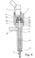
- FIG. 4 shows the valve device 1 in a third embodiment. Again, a side port 24 is provided for the supply of the fuel, not shown.
- valve 9 is formed as an inwardly opening needle valve and that, accordingly, the translation device 8 is formed somewhat differently.
- the third embodiment namely the direction of movement or stroke direction of the actuator 7 and the resulting movement of the valve 9 and its valve element 16 are directed in opposite directions. This is achieved in that the output point 14c of the first lever 10 and thus the drive point 14b of the second lever 11 outside the Bearing points 14a of the second lever 11 are; the bearing point 14a of the second lever 11 thus lies between its drive point 14b and its output point 14c.
- both levers 10, 11 pivot in the same direction of rotation, namely in the clockwise direction, so that the lower lever 11 swings upward, and the lever 11 preferably cross-valve element 16 to open the valve 9 in the illustration of FIG 4 lifts up against the force of the return device 19.
- Fig. 4 further illustrates the preferably floating bearing of the levers 10, 11.
- an insert 27 is inserted into the housing 21, which supports the lever 10 and / or 11 and preferably has a recess for laterally guiding the lever 10 and / or 11 ,
- the two levers 11 are preferably formed substantially rod-shaped, elongated, plate-shaped or annular, wherein the actual storage and mechanics otherwise substantially correspond to the first two embodiments.
- the proposed valve device 1 enables activation or opening times of 0.1 ms and thus multiple injections or injections of fuel during one cycle.
- a general advantage is that the proposed valve device 1 is very inexpensive to produce, especially when using a piezoelectric actuator. 7
- the individual components are made resistant to the fuel. This is especially true when using hydrogen, since, for example, titanium alloys or elastomers are not resistant to hydrogen.
Landscapes
- Engineering & Computer Science (AREA)
- Chemical & Material Sciences (AREA)
- Combustion & Propulsion (AREA)
- Mechanical Engineering (AREA)
- General Engineering & Computer Science (AREA)
- Chemical Kinetics & Catalysis (AREA)
- General Chemical & Material Sciences (AREA)
- Oil, Petroleum & Natural Gas (AREA)
- Analytical Chemistry (AREA)
- Fuel-Injection Apparatus (AREA)
Abstract
Claims (14)
- Dispositif (1) faisant office de soupape pour un moteur à combustion interne (2) à des fins d'injection d'un carburant gazeux, comprenant un actionneur (7), un dispositif de démultiplication (8) pour augmenter la course de l'actionneur (7) et une soupape (9) qui peut être actionnée par l'actionneur (7) au moyen du dispositif de démultiplication (8), la soupape (9), respectivement son élément (16) faisant office de soupape, commandant directement l'injection, respectivement le courant du carburant gazeux dans une chambre de combustion correspondante (3) du moteur à combustion interne (2), caractérisé en ce que le dispositif de démultiplication (8) comprend au moins deux leviers (10, 11) qui sont montés en série pour augmenter la course de l'actionneur (7) dans le but d'actionner la soupape (9) et/ou en ce que le dispositif (1) faisant office de soupape présente un dispositif (12) faisant office de capteur attribué à un élément mobile (16) faisant office de soupape de la soupape (9) pour enregistrer la position ou la course de l'élément (16) faisant office de soupape.
- Dispositif faisant office de soupape selon la revendication 1, caractérisé en ce que l'actionneur (7) travaille dans le mode électromagnétique, piézo-électrique ou magnétostrictif et/ou en ce que l'axe actif (A) de l'actionneur (7) s'étend parallèlement en décalage ou en position coaxiale par rapport à l'axe d'actionnement (V) de la soupape (9) ou bien transversalement ou en inclinaison par rapport à l'axe d'actionnement (V) de la soupape (9).
- Dispositif faisant office de soupape selon l'une quelconque des revendications précédentes, caractérisé en ce que le dispositif de démultiplication (8) travaille exclusivement de manière mécanique à l'aide d'un levier et/ou agit directement sur la soupape (9), respectivement sur l'élément de cette dernière faisant office de soupape, pour son actionnement, et/ou en ce que le dispositif de démultiplication (8) présente un rapport de démultiplication supérieur à 5, en particulier supérieur à 10 ou 12, et en ce qu'un moyen de ressort est disposé en amont ou en aval du dispositif de démultiplication (8), si bien que du jeu peut se manifester entre l'actionneur (7) et le dispositif de démultiplication (8) ou à un élément de démultiplication disposé en position intermédiaire, un tel jeu étant néanmoins supprimé entre les leviers (10, 11) du dispositif de démultiplication (8) ou entre le dispositif de démultiplication (8) et la soupape (9).
- Dispositif faisant office de soupape selon l'une quelconque des revendications précédentes, caractérisé en ce que les leviers (10, 11) sont réalisés en forme de disques, sous forme longitudinale, en forme de plaques, en forme de barres et/ou de manière rigide et/ou présentent un module d'élasticité élevé, et/ou en ce que les leviers (10, 11) sont réalisés en un alliage de métaux légers, en un matériau composite et/ou en céramique, et/ou en ce qu'au moins un levier (10, 11) est recouvert, au moins dans certaines zones, afin de minimiser l'usure et/ou est muni d'une pièce rapportée de préférence en céramique ou en métal dur (13).
- Dispositif faisant office de soupape selon l'une quelconque des revendications précédentes, caractérisé en ce que les leviers (10, 11) sont montés respectivement en pivotant autour d'un point de pivot (14a), en particulier dans lequel un point d'entraînement (14b) est disposé respectivement entre le point de pivot (14a) et un point de sortie (14c), et/ou en ce que des points d'entraînement (14b) des leviers (10, 11) sont disposés sur des côtés opposés de l'axe d'actionnement (V) de la soupape (9), et/ou en ce que, lors de l'actionnement de la soupape (9), les leviers (10, 11) sont en mesure de pivoter dans la même direction ou dans des directions opposées.
- Dispositif faisant office de soupape selon l'une quelconque des revendications précédentes, caractérisé en ce que les leviers (10, 11) s'étendent essentiellement parallèlement l'un à l'autre, et/ou en ce que les leviers (10, 11) sont montés en flottement ; et/ou en ce que la soupape (9), respectivement son élément (16) faisant office de soupape, peut être actionnée, en particulier peut s'ouvrir dans la direction d'injection ou dans la direction opposée à cette dernière.
- Dispositif faisant office de soupape selon l'une quelconque des revendications précédentes, caractérisé en ce qu'un dispositif de rappel (19) pour la fermeture ou l'ouverture de la soupape (9) est attribué à la soupape (9), la soupape (9) étant à même de s'ouvrir, respectivement de se fermer sous l'effet de l'actionneur (7) à l'encontre de cette force de rappel, et/ou en ce qu'un injecteur est monté en aval de la soupape (9), et/ou en ce qu'on peut faire varier le degré d'ouverture de la soupape (9), respectivement de la course de l'élément (16) faisant office de soupape, en particulier pour la commande de la quantité d'injection et/ou la configuration de l'allure de l'injection.
- Dispositif faisant office de soupape selon l'une quelconque des revendications précédentes, caractérisé en ce que le dispositif (12) faisant office de capteur détecte dans le temps la position ou la course de l'élément (16) faisant office de soupape ou bien l'enregistre en continu et fournit des signaux correspondants, et/ou en ce que le dispositif (1) faisant office de soupape présente une évaluation de signaux (20a), traite les signaux du dispositif (12) faisant office de capteur et/ou en particulier les fournit à un dispositif de commande (20b) monté à la suite, en particulier dans lequel le traitement de signaux (20a) est incorporé dans le dispositif (1) faisant office de soupape, et/ou en ce qu'un dispositif de commande (20b) est attribué au dispositif (1) faisant office de soupape, dispositif à l'aide duquel l'actionneur (7) peut être commandé ou réglé, en fonction des signaux du dispositif (12) faisant office de capteur de telle sorte que l'on limite ou que l'on minimise le jeu entre l'actionneur (7) et la soupape (9) ou son élément (16) faisant office de soupape lorsque la soupape (9) est fermée ou est à l'état de repos.
- Dispositif faisant office de soupape selon l'une quelconque des revendications précédentes, caractérisé en ce que le dispositif (1) faisant office de soupape présente un boîtier (21) pour la réception et/ou le support de l'actionneur (7), du dispositif de démultiplication (8), de la soupape (9), d'un dispositif de rappel (19), d'un injecteur, du dispositif (12) faisant office de capteur et/ou d'un dispositif de commande qui commande l'actionneur (7), et/ou en ce que l'actionneur (7) a été rendu étanche aux gaz, vis-à-vis du carburant, en particulier au moyen d'une membrane, de préférence du dispositif de démultiplication (8), en particulier dans lequel la membrane (22) vient s'insérer entre un poussoir (15) de l'actionneur (7) et le dispositif de démultiplication (8).
- Procédé pour l'injection directe d'un carburant gazeux dans une chambre de combustion (3) d'un moteur à combustion interne (2), dans lequel un actionneur (7) actionne, au moyen d'un dispositif de démultiplication (8) qui augmente la course de l'actionneur, un élément (16) faisant office de soupape d'une soupape (9) à l'encontre de la force de dispositif de rappel (19), la position ou la course de l'élément (16) faisant office de soupape étant enregistrée au moyen d'un dispositif (12) faisant office de capteur attribué à la soupape, et dans lequel l'actionneur (7) est commandé ou réglé en fonction des signaux du dispositif (12) faisant office de capteur de telle sorte que l'on limite ou que l'on minimise le jeu entre l'actionneur (7) et la soupape (9) ou son élément (16) faisant office de soupape lorsque la soupape (9) est fermée ou est à l'état de repos, l'injection, respectivement le courant du carburant gazeux étant guidé directement dans la chambre de combustion (3).
- Procédé selon la revendication 10, caractérisé en ce que, dans un processus de réglage, à partir d'un état dans lequel la soupape (9) est à l'état de repos ou est fermée, l'actionneur (7) est activé progressivement, en particulier lentement ou pas à pas ou bien sa course est soumise à une augmentation dans la direction orientée vers l'actionnement de la soupape (9), jusqu'à ce que l'on enregistre un premier actionnement de la soupape (9), et en ce qu'ensuite, l'activation de l'actionneur (7), respectivement de la course de ce dernier, est de nouveau diminuée d'une mesure déterminée jusqu'à une valeur de base afin de limiter ou de minimiser le jeu entre l'actionneur (7) et la soupape (9) lorsque la soupape (9) est fermée ou est à l'état de repos.
- Procédé selon la revendication 11, caractérisé en ce que la valeur de base pour un réglage de départ de l'actionneur (7) est utilisée lors des processus d'injection suivants, et/ou en ce que la mesure est prédéfinie de manière fixe, et réglée en fonction de paramètres d'actionnement, respectivement en fonction de la définition des réseaux de caractéristiques d'actionnement et/ou est déterminée à partir de valeurs précédentes, et/ou en ce que la valeur de base future est déterminée à partir d'une valeur de base déterminée actuellement et à partir de valeurs de base précédentes, en particulier est réglée en fonction de paramètres d'actionnement, respectivement en fonction de la définition des réseaux de caractéristiques d'actionnement.
- Procédé selon la revendication 11 ou 12, caractérisé en ce que le processus de réglage est répété après un nombre prédéterminé de processus d'injection ou de cycles de moteur et/ou dans le cas d'un retour incomplet de la soupape (9) à son état de repos ou fermé, et/ou en ce que les valeurs de base sont mémorisées en continu et/ou sont évaluées pour analyser l'usure.
- Utilisation d'un moyen (25) faisant office de ressort dans un dispositif (1) faisant office de soupape pour l'injection d'un carburant gazeux, dans lequel un actionneur (7) actionne, au moyen d'un dispositif de démultiplication (8) qui augmente la course de l'actionneur, une soupape (9) à l'encontre de la force de dispositif de rappel (19), le moyen (25) faisant office de ressort étant attribué au dispositif de démultiplication (8) ou à un élément de démultiplication entre l'actionneur (7) et le dispositif de démultiplication (8) de telle sorte que l'on supprime le jeu dans le dispositif de démultiplication (8) et/ou entre le dispositif de démultiplication (8) et l'élément de démultiplication et/ou entre le dispositif de démultiplication (8) et la soupape (9), un dispositif (1) faisant office de soupape selon l'une quelconque des revendications 1 à 9 étant utilisé.
Applications Claiming Priority (2)
| Application Number | Priority Date | Filing Date | Title |
|---|---|---|---|
| DE10326707A DE10326707B3 (de) | 2003-06-11 | 2003-06-11 | Ventilvorrichtung und Verfahren zum Einblasen von gasförmigem Kraftstoff |
| PCT/EP2004/006130 WO2004109087A1 (fr) | 2003-06-11 | 2004-06-07 | Systeme de soupape et procede pour injecter du carburant sous forme gazeuse |
Publications (2)
| Publication Number | Publication Date |
|---|---|
| EP1642018A1 EP1642018A1 (fr) | 2006-04-05 |
| EP1642018B1 true EP1642018B1 (fr) | 2007-01-24 |
Family
ID=33495019
Family Applications (1)
| Application Number | Title | Priority Date | Filing Date |
|---|---|---|---|
| EP04739663A Expired - Lifetime EP1642018B1 (fr) | 2003-06-11 | 2004-06-07 | Systeme de soupape et procede pour injecter du carburant sous forme gazeuse |
Country Status (6)
| Country | Link |
|---|---|
| US (1) | US7225790B2 (fr) |
| EP (1) | EP1642018B1 (fr) |
| JP (1) | JP4904586B2 (fr) |
| CN (1) | CN100507254C (fr) |
| DE (2) | DE10326707B3 (fr) |
| WO (1) | WO2004109087A1 (fr) |
Families Citing this family (57)
| Publication number | Priority date | Publication date | Assignee | Title |
|---|---|---|---|---|
| US7040281B2 (en) * | 2000-10-22 | 2006-05-09 | Westport Research Inc. | Method of injecting a gaseous fuel into an internal combustion engine |
| US7281515B2 (en) * | 2000-10-22 | 2007-10-16 | Westport Power Inc. | Method of injecting a gaseous fuel into an internal combustion engine |
| DE102004028522A1 (de) * | 2004-06-11 | 2005-12-29 | Robert Bosch Gmbh | Kraftstoffinjektor mit variabler Aktorhubübersetzung |
| US7467750B2 (en) * | 2004-07-20 | 2008-12-23 | Mazrek Ltd. | Needle-spring locking device for pump-injector (injector) for internal combustion engines |
| DE102005037419A1 (de) * | 2005-08-08 | 2007-02-22 | Siemens Ag | Injektor zur Direktinjektion von brennbaren Fluiden |
| DE102005042106A1 (de) * | 2005-09-05 | 2007-03-15 | Siemens Ag | Betriebsverfahren zur Direkteinspritzung von Brennstoffen in einer Verbrennungs-Kraftmaschine |
| DE502005010937D1 (de) * | 2005-09-06 | 2011-03-17 | Continental Automotive Gmbh | Kraftstoffeinspritzventil |
| DE102006013512A1 (de) * | 2006-03-23 | 2007-09-27 | Siemens Ag | Fluiddosiervorrichtung und System zur Fluiddosierung |
| DE102006017034B4 (de) * | 2006-04-11 | 2008-01-24 | Siemens Ag | Piezo-Aktor, Verfahren zum Herstellen eines Piezo-Aktors und Einspritzsystem mit einem solchen |
| DE102006051206A1 (de) * | 2006-10-30 | 2008-05-08 | Robert Bosch Gmbh | Kraftstoffinjektor mit einer Messeinrichtung |
| US8074625B2 (en) | 2008-01-07 | 2011-12-13 | Mcalister Technologies, Llc | Fuel injector actuator assemblies and associated methods of use and manufacture |
| KR101000169B1 (ko) * | 2008-12-03 | 2010-12-10 | 기아자동차주식회사 | 엘피아이 인젝터용 노즐 |
| DE102008060518A1 (de) * | 2008-12-04 | 2010-07-15 | Continental Automotive Gmbh | Einspritzventil |
| US8991423B2 (en) | 2010-05-10 | 2015-03-31 | Go Natural Cng, Llc | Fuel interface modules and related systems and methods |
| DE102010039478A1 (de) | 2010-08-18 | 2012-02-23 | Continental Automotive Gmbh | Antriebsvorrichtung für ein Einspritzventil und Einspritzventil |
| DE102010063246B4 (de) * | 2010-12-16 | 2015-12-03 | Continental Automotive Gmbh | Antriebsvorrichtung für ein Einspritzventil und Einspritzventil |
| JP5482836B2 (ja) | 2011-09-20 | 2014-05-07 | 株式会社デンソー | 燃料噴射弁及び燃料噴射弁の製造方法 |
| DE102011090196A1 (de) * | 2011-12-30 | 2013-07-04 | Continental Automotive Gmbh | Hebelvorrichtung und Einspritzventil |
| DE102011090200A1 (de) * | 2011-12-30 | 2013-07-04 | Continental Automotive Gmbh | Hebelvorrichtung und Einspritzventil |
| DE102012207842A1 (de) | 2012-05-10 | 2013-11-14 | Continental Automotive Gmbh | Einspritzventil |
| JP6175059B2 (ja) * | 2012-06-08 | 2017-08-02 | 本田技研工業株式会社 | 燃料噴射装置 |
| DE102012216688A1 (de) * | 2012-09-18 | 2014-03-20 | Robert Bosch Gmbh | Brennstoffeinspritzventil |
| DE102012218763A1 (de) * | 2012-10-15 | 2014-04-17 | Continental Automotive Gmbh | Mechanische Übersetzungseinrichtung sowie Hebeleinrichtung für einen Kraftstoffinjektor |
| WO2014066696A1 (fr) * | 2012-10-25 | 2014-05-01 | Picospray, Llc | Système d'injection de carburant |
| US9309846B2 (en) | 2012-11-12 | 2016-04-12 | Mcalister Technologies, Llc | Motion modifiers for fuel injection systems |
| US9091238B2 (en) | 2012-11-12 | 2015-07-28 | Advanced Green Technologies, Llc | Systems and methods for providing motion amplification and compensation by fluid displacement |
| US20140130773A1 (en) * | 2012-11-12 | 2014-05-15 | Mcalister Technologies, Llc | Mechanical motion amplification for new thermodynamic cycles |
| USD697195S1 (en) | 2012-11-21 | 2014-01-07 | Trilogy Engineered Solutions, LLC | Compressed natural gas manifold |
| WO2014081833A1 (fr) | 2012-11-21 | 2014-05-30 | Trilogy Engineered Solutions | Procédés et systèmes pour un système à gaz naturel comprimé (cng) |
| DE102012223149B4 (de) * | 2012-12-14 | 2017-09-14 | Continental Automotive Gmbh | Injektor sowie Verfahren zum Steuern oder Regeln eines Injektors |
| DE102013220528B4 (de) * | 2013-10-11 | 2015-05-07 | Continental Automotive Gmbh | Einspritzventil und Verfahren zum Betreiben eines Einspritzventils |
| USD759229S1 (en) | 2013-11-20 | 2016-06-14 | Worthington Industries | Fuel tank frame assembly |
| US20160222949A1 (en) * | 2015-01-30 | 2016-08-04 | Caterpillar Inc. | Pumping mechanism with plunger |
| TWI572411B (zh) * | 2014-04-01 | 2017-03-01 | All Ring Tech Co Ltd | Liquid material extrusion method and device |
| US9803555B2 (en) * | 2014-04-23 | 2017-10-31 | General Electric Company | Fuel delivery system with moveably attached fuel tube |
| FR3024183B1 (fr) * | 2014-07-22 | 2019-07-26 | Delphi Technologies Ip Limited | Injecteur de carburant |
| DK3015699T3 (en) * | 2014-10-31 | 2019-03-11 | Winterthur Gas & Diesel Ag | Gas supply system with a control system and cylinder for a piston combustion engine, piston combustion engine and method of operation of a piston combustion engine |
| CN104847541B (zh) * | 2015-04-15 | 2017-04-26 | 太原理工大学 | 一种富氧燃烧发动机系统 |
| DK3147477T3 (en) * | 2015-09-23 | 2019-01-21 | Winterthur Gas & Diesel Ag | Gas supply system and cylinder liner for a piston combustion engine, piston combustion engine and method of operation of a piston combustion engine |
| PL3403727T3 (pl) * | 2016-01-16 | 2024-11-18 | Musashi Engineering, Inc. | Urządzenie do wyrzucania ciekłego materiału |
| CN105797889B (zh) * | 2016-02-03 | 2017-12-05 | 惠州三高电子科技有限公司 | 一种喷雾产品的喷气控制装置 |
| EP3455498B1 (fr) | 2016-05-12 | 2024-07-03 | Briggs & Stratton, LLC | Injecteur de distribution de carburant |
| DE102016108811A1 (de) * | 2016-05-12 | 2017-11-16 | Marco Systemanalyse Und Entwicklung Gmbh | Piezoelektrische Stellvorrichtung |
| DE102016212075A1 (de) * | 2016-07-04 | 2018-01-04 | Robert Bosch Gmbh | Ventil zum Eindüsen von gasförmigem Kraftstoff |
| JP1574166S (fr) | 2016-08-31 | 2020-04-06 | ||
| CN106523192A (zh) * | 2016-11-28 | 2017-03-22 | 哈尔滨工程大学 | 一种反向作动式气体/双燃料发动机天然气喷射装置 |
| US10947940B2 (en) | 2017-03-28 | 2021-03-16 | Briggs & Stratton, Llc | Fuel delivery system |
| CN109057998B (zh) * | 2018-09-21 | 2024-10-01 | 英嘉动力科技无锡有限公司 | 一种喷射器双运动副衔接结构 |
| DE102018216338B4 (de) * | 2018-09-25 | 2022-05-12 | Festo Se & Co. Kg | Diagnoseeinrichtung, System, Verfahren und Steuereinrichtung |
| US11668270B2 (en) | 2018-10-12 | 2023-06-06 | Briggs & Stratton, Llc | Electronic fuel injection module |
| KR102902059B1 (ko) * | 2019-05-12 | 2025-12-19 | 노드슨 코포레이션 | 기계식 증폭기를 갖는 분배 시스템 |
| DE102019123310A1 (de) * | 2019-08-30 | 2021-03-04 | Man Energy Solutions Se | Gasventil einer Brennkraftmaschine und Brennkraftmaschine |
| CN112459941B (zh) * | 2020-11-05 | 2021-11-12 | 上海工程技术大学 | 直接控制喷油嘴开关的压电式共轨喷油器 |
| CN116457747A (zh) | 2020-11-16 | 2023-07-18 | Tdk电子股份有限公司 | 用于生成放大触觉信号的致动器单元和方法 |
| DE102021121334A1 (de) * | 2021-04-27 | 2022-10-27 | Dürr Systems Ag | Piezo-Aktorvorrichtung |
| US11906067B2 (en) * | 2022-01-21 | 2024-02-20 | Hamilton Sundstrand Corporation | Active valve shimming |
| US12104560B1 (en) | 2022-10-17 | 2024-10-01 | Budhadeb Mahakul | Direct in cylinder injector for gaseous fuel |
Family Cites Families (48)
| Publication number | Priority date | Publication date | Assignee | Title |
|---|---|---|---|---|
| US1341911A (en) * | 1918-12-09 | 1920-06-01 | Robert Pile Doxford | Fuel-injection valve for oil-engines |
| US3501099A (en) * | 1967-09-27 | 1970-03-17 | Physics Int Co | Electromechanical actuator having an active element of electroexpansive material |
| US3614486A (en) * | 1969-11-10 | 1971-10-19 | Physics Int Co | Lever motion multiplier driven by electroexpansive material |
| US4022166A (en) * | 1975-04-03 | 1977-05-10 | Teledyne Industries, Inc. | Piezoelectric fuel injector valve |
| JPS5879116A (ja) * | 1981-11-05 | 1983-05-12 | Nissan Motor Co Ltd | 内燃機関の燃料噴射量検知装置 |
| JPS601369A (ja) * | 1983-06-16 | 1985-01-07 | Nippon Soken Inc | 燃料噴射弁 |
| US4530487A (en) * | 1984-03-16 | 1985-07-23 | Tew Sydney K | Direct drive servovalve and fuel control system incorporating same |
| JPS629075A (ja) * | 1985-07-03 | 1987-01-17 | Ckd Corp | 圧電式制御弁 |
| DE3533975A1 (de) * | 1985-09-24 | 1987-03-26 | Bosch Gmbh Robert | Zumessventil zur dosierung von fluessigkeiten oder gasen |
| JPS62157274A (ja) * | 1985-12-28 | 1987-07-13 | Aisan Ind Co Ltd | 燃料噴射弁 |
| JPS636282A (ja) * | 1986-06-23 | 1988-01-12 | Ckd Controls Ltd | 積層形圧電素子を駆動源とした開閉弁 |
| JPS6346672U (fr) * | 1986-09-12 | 1988-03-29 | ||
| US4865001A (en) * | 1988-11-28 | 1989-09-12 | Energy Conversions, Inc. | Gaseous fuel injector valve |
| EP0400504B1 (fr) * | 1989-06-02 | 1994-08-10 | MATRIX S.r.l. | Clapet électromagnétique pour fluide sous pression, par exemple circuits pneumatiques |
| ATE115683T1 (de) * | 1990-03-09 | 1994-12-15 | Siemens Ag | Ventil mit piezoelektrischem antrieb. |
| US5163623A (en) * | 1991-05-31 | 1992-11-17 | General Motors Corporation | Fuel injector |
| DE4325904C2 (de) * | 1993-08-02 | 1995-07-20 | Daimler Benz Ag | Für eine Dieselbrennkraftmaschine vorgesehene Kraftstoffeinspritzanlage mit einer den Kraftstoff fördernden Hochdruckpumpe in eine gemeinsame Versorgungsleitung (Common-Rail) für alle Einspritzdüsen |
| DE19500706C2 (de) * | 1995-01-12 | 2003-09-25 | Bosch Gmbh Robert | Zumeßventil zur Dosierung von Flüssigkeiten oder Gasen |
| DE19543080C2 (de) * | 1995-11-18 | 1999-10-28 | Man B & W Diesel Ag | Vorrichtung zur Steuerung von Ventilen einer Brennkraftmaschine, insbesondere des Gaszufuhrventils eines Gasmotors |
| JP3740733B2 (ja) * | 1996-02-13 | 2006-02-01 | いすゞ自動車株式会社 | 内燃機関の燃料噴射装置 |
| JPH09287538A (ja) * | 1996-04-19 | 1997-11-04 | Hitachi Ltd | 燃料噴射弁及び燃料噴射装置 |
| EP0931358B1 (fr) * | 1996-09-30 | 2002-02-27 | Siemens Aktiengesellschaft | Organe de reglage comportant un actionneur a longueur reglable et dispositif pour la transmission du deplacement d'un actionneur |
| DE19712374C2 (de) | 1997-03-25 | 2001-07-19 | Bosch Gmbh Robert | Lage- und Wegsensor |
| DE19712921A1 (de) * | 1997-03-27 | 1998-10-01 | Bosch Gmbh Robert | Brennstoffeinspritzventil mit piezoelektrischem oder magnetostriktivem Aktor |
| DE19721241C1 (de) * | 1997-05-21 | 1998-11-05 | Hatz Motoren | Pumpedüse |
| US6607178B1 (en) | 1997-09-29 | 2003-08-19 | Siemens Aktiengesellschaft | Thrust device, fuel injection valve having such a device, and method for manufacturing a thrust transfer element |
| DE19751661C2 (de) * | 1997-11-21 | 2000-08-03 | Daimler Chrysler Ag | Kapazitive Meßeinrichtung |
| DE19757659C1 (de) * | 1997-12-23 | 1999-06-17 | Siemens Ag | Einspritzventil mit einer Ausgleichsfläche |
| AT2962U3 (de) * | 1998-07-02 | 1999-11-25 | Avl List Gmbh | Einspritzeinrichtung für eine brennkraftmaschine |
| DE19835494C2 (de) * | 1998-08-06 | 2000-06-21 | Bosch Gmbh Robert | Pumpe-Düse-Einheit |
| DE19857615C1 (de) * | 1998-12-14 | 2000-07-13 | Siemens Ag | Hebelübersetzer |
| DE19905340C2 (de) * | 1999-02-09 | 2001-09-13 | Siemens Ag | Verfahren und Anordnung zur Voreinstellung und dynamischen Nachführung piezoelektrischer Aktoren |
| DE19911048A1 (de) * | 1999-03-12 | 2000-09-14 | Bosch Gmbh Robert | Brennstoffeinspritzventil |
| US6969404B2 (en) | 1999-10-08 | 2005-11-29 | Ferree Bret A | Annulus fibrosis augmentation methods and apparatus |
| DE19930309C2 (de) | 1999-07-01 | 2001-12-06 | Siemens Ag | Verfahren und Vorrichtung zur Regelung der Einspritzmenge bei einem Kraftstoffeinspritzventil mit Piezoelement-Aktor |
| US6253736B1 (en) * | 1999-08-10 | 2001-07-03 | Cummins Engine Company, Inc. | Fuel injector nozzle assembly with feedback control |
| DE19938999C2 (de) | 1999-08-17 | 2003-10-02 | Siemens Ag | Einspritzventil mit einem geschmierten Übertragungselement |
| DE19952057A1 (de) * | 1999-10-28 | 2001-05-03 | Bosch Gmbh Robert | Brennstoffeinspritzventil |
| US6400066B1 (en) * | 2000-06-30 | 2002-06-04 | Siemens Automotive Corporation | Electronic compensator for a piezoelectric actuator |
| DE10052336B4 (de) * | 2000-10-22 | 2004-04-22 | Westport Germany Gmbh | Brennkraftmaschine mit Einblasung von gasförmigem Kraftstoff |
| DE10101799A1 (de) * | 2001-01-17 | 2002-07-18 | Bosch Gmbh Robert | Ventil zum Steuern von Flüssigkeiten |
| US6390069B1 (en) * | 2001-01-26 | 2002-05-21 | Detroit Diesel Corporation | Fuel injector assembly and internal combustion engine including same |
| WO2002086982A1 (fr) | 2001-04-20 | 2002-10-31 | Siemens Aktiengesellschaft | Dispositif pour transmettre la deviation d'un actionneur, et son procede de production |
| DE10120709A1 (de) * | 2001-04-27 | 2002-10-31 | Bosch Gmbh Robert | Ventil zum Steuern von Flüssigkeiten |
| US6595436B2 (en) * | 2001-05-08 | 2003-07-22 | Cummins Engine Company, Inc. | Proportional needle control injector |
| DE10129375B4 (de) * | 2001-06-20 | 2005-10-06 | Mtu Friedrichshafen Gmbh | Injektor mit Piezo-Aktuator |
| US6845745B2 (en) * | 2002-02-26 | 2005-01-25 | Exxonmobil Research And Engineering Company | Modification of lubricant properties in a recirculating lubricant system |
| DE10304240A1 (de) * | 2003-02-03 | 2004-10-28 | Volkswagen Mechatronic Gmbh & Co. Kg | Vorrichtung zum Übertragen einer Auslenkung eines Aktors |
-
2003
- 2003-06-11 DE DE10326707A patent/DE10326707B3/de not_active Withdrawn - After Issue
-
2004
- 2004-06-07 EP EP04739663A patent/EP1642018B1/fr not_active Expired - Lifetime
- 2004-06-07 WO PCT/EP2004/006130 patent/WO2004109087A1/fr not_active Ceased
- 2004-06-07 JP JP2006515839A patent/JP4904586B2/ja not_active Expired - Fee Related
- 2004-06-07 CN CNB2004800226549A patent/CN100507254C/zh not_active Expired - Fee Related
- 2004-06-07 DE DE502004002791T patent/DE502004002791D1/de not_active Expired - Lifetime
-
2005
- 2005-04-15 US US11/107,428 patent/US7225790B2/en not_active Expired - Fee Related
Also Published As
| Publication number | Publication date |
|---|---|
| US7225790B2 (en) | 2007-06-05 |
| CN100507254C (zh) | 2009-07-01 |
| DE502004002791D1 (de) | 2007-03-15 |
| US20050199746A1 (en) | 2005-09-15 |
| DE10326707B3 (de) | 2005-01-27 |
| EP1642018A1 (fr) | 2006-04-05 |
| CN1833101A (zh) | 2006-09-13 |
| JP2006527346A (ja) | 2006-11-30 |
| JP4904586B2 (ja) | 2012-03-28 |
| WO2004109087A1 (fr) | 2004-12-16 |
Similar Documents
| Publication | Publication Date | Title |
|---|---|---|
| EP1642018B1 (fr) | Systeme de soupape et procede pour injecter du carburant sous forme gazeuse | |
| EP1001143B1 (fr) | Commande de soupape pour soupapes d'admission et d'échappement de moteur à combustion interne | |
| EP1831537B1 (fr) | Injecteur de systeme d'injection de carburant d'un moteur a combustion interne | |
| DE19946827C1 (de) | Ventil zum Steuern von Flüssigkeiten | |
| EP0745764A2 (fr) | Soupape d'injection de combustible pour moteurs à combustion interne | |
| EP0908617A1 (fr) | Dispositif d'injection de combustible | |
| DE10221384A1 (de) | Kraftstoffeinspritzeinrichtung für eine Brennkraftmaschine | |
| EP1856403B1 (fr) | Injecteur de carburant comprenant un element de soupape d'injection a commande directe qui presente un double siege | |
| WO1999018349A1 (fr) | Soupape d'injection a commande directe, en particulier soupape d'injection de carburant | |
| EP1252433A2 (fr) | Soupape d'injection de carburant pour moteurs a combustion interne | |
| EP1682769A1 (fr) | Injecteur de carburant dote d'un element de soupape d'injection en plusieurs parties, en commande directe | |
| EP2580462B1 (fr) | Soupape d'injection dotée d'une commande directe et d'une servocommande | |
| EP1488096B1 (fr) | Soupape d'injection de carburant | |
| WO2003054375A1 (fr) | Dispositif d'injection de carburant pour moteur a combustion interne | |
| WO2002048540A1 (fr) | Dispositif d'injection de carburant pour un moteur a combustion interne | |
| DE10123994A1 (de) | Kraftstoffeinspritzeinrichtung für eine Brennkraftmaschine | |
| DE10063261A1 (de) | Brennstoffeinspritzventil | |
| EP1451465B1 (fr) | Unite pompe-injecteur | |
| WO2003098029A1 (fr) | Soupape d'injection de carburant de moteurs a combustion interne | |
| EP1430219A1 (fr) | Systeme d'injection de carburant pour moteur a combustion interne | |
| DE10155674A1 (de) | Kraftstoffeinspritzeinrichtung für eine Brennkraftmaschine | |
| DE10162384A1 (de) | Kraftstoffeinspritzeinrichtung für eine Brennkraftmaschine | |
| EP1601870A1 (fr) | Soupape d'injection de carburant pour un moteur a combustion interne | |
| DE102004029363A1 (de) | Piezoelektrischer Stellantrieb für einen Kraftstoffinjektor einer Brennkraftmaschine sowie Verwendung hierfür | |
| EP1430216A1 (fr) | Dispositif d'injection de carburant pour un moteur a combustion interne |
Legal Events
| Date | Code | Title | Description |
|---|---|---|---|
| PUAI | Public reference made under article 153(3) epc to a published international application that has entered the european phase |
Free format text: ORIGINAL CODE: 0009012 |
|
| 17P | Request for examination filed |
Effective date: 20060106 |
|
| AK | Designated contracting states |
Kind code of ref document: A1 Designated state(s): DE FR GB |
|
| GRAP | Despatch of communication of intention to grant a patent |
Free format text: ORIGINAL CODE: EPIDOSNIGR1 |
|
| DAX | Request for extension of the european patent (deleted) | ||
| RBV | Designated contracting states (corrected) |
Designated state(s): DE FR GB |
|
| RAP1 | Party data changed (applicant data changed or rights of an application transferred) |
Owner name: WESTPORT RESEARCH INC. |
|
| GRAS | Grant fee paid |
Free format text: ORIGINAL CODE: EPIDOSNIGR3 |
|
| RAP1 | Party data changed (applicant data changed or rights of an application transferred) |
Owner name: WESTPORT POWER INC. |
|
| GRAA | (expected) grant |
Free format text: ORIGINAL CODE: 0009210 |
|
| AK | Designated contracting states |
Kind code of ref document: B1 Designated state(s): DE FR GB |
|
| REG | Reference to a national code |
Ref country code: GB Ref legal event code: FG4D Free format text: NOT ENGLISH |
|
| REF | Corresponds to: |
Ref document number: 502004002791 Country of ref document: DE Date of ref document: 20070315 Kind code of ref document: P |
|
| ET | Fr: translation filed | ||
| GBV | Gb: ep patent (uk) treated as always having been void in accordance with gb section 77(7)/1977 [no translation filed] |
Effective date: 20070124 |
|
| PG25 | Lapsed in a contracting state [announced via postgrant information from national office to epo] |
Ref country code: GB Free format text: LAPSE BECAUSE OF FAILURE TO SUBMIT A TRANSLATION OF THE DESCRIPTION OR TO PAY THE FEE WITHIN THE PRESCRIBED TIME-LIMIT Effective date: 20070124 |
|
| PLBE | No opposition filed within time limit |
Free format text: ORIGINAL CODE: 0009261 |
|
| STAA | Information on the status of an ep patent application or granted ep patent |
Free format text: STATUS: NO OPPOSITION FILED WITHIN TIME LIMIT |
|
| 26N | No opposition filed |
Effective date: 20071025 |
|
| REG | Reference to a national code |
Ref country code: DE Ref legal event code: R082 Ref document number: 502004002791 Country of ref document: DE Representative=s name: VON ROHR PATENTANWAELTE PARTNERSCHAFT MBB, DE |
|
| REG | Reference to a national code |
Ref country code: FR Ref legal event code: PLFP Year of fee payment: 13 |
|
| REG | Reference to a national code |
Ref country code: FR Ref legal event code: PLFP Year of fee payment: 14 |
|
| REG | Reference to a national code |
Ref country code: FR Ref legal event code: PLFP Year of fee payment: 15 |
|
| PGFP | Annual fee paid to national office [announced via postgrant information from national office to epo] |
Ref country code: FR Payment date: 20190625 Year of fee payment: 16 |
|
| PGFP | Annual fee paid to national office [announced via postgrant information from national office to epo] |
Ref country code: DE Payment date: 20190627 Year of fee payment: 16 |
|
| REG | Reference to a national code |
Ref country code: DE Ref legal event code: R119 Ref document number: 502004002791 Country of ref document: DE |
|
| PG25 | Lapsed in a contracting state [announced via postgrant information from national office to epo] |
Ref country code: FR Free format text: LAPSE BECAUSE OF NON-PAYMENT OF DUE FEES Effective date: 20200630 |
|
| PG25 | Lapsed in a contracting state [announced via postgrant information from national office to epo] |
Ref country code: DE Free format text: LAPSE BECAUSE OF NON-PAYMENT OF DUE FEES Effective date: 20210101 |