EP1642105B1 - Systeme de transmission et procede de mesure de force d'entrainement - Google Patents
Systeme de transmission et procede de mesure de force d'entrainement Download PDFInfo
- Publication number
- EP1642105B1 EP1642105B1 EP04748657A EP04748657A EP1642105B1 EP 1642105 B1 EP1642105 B1 EP 1642105B1 EP 04748657 A EP04748657 A EP 04748657A EP 04748657 A EP04748657 A EP 04748657A EP 1642105 B1 EP1642105 B1 EP 1642105B1
- Authority
- EP
- European Patent Office
- Prior art keywords
- measuring
- transmission system
- chain
- force sensor
- sensor
- Prior art date
- Legal status (The legal status is an assumption and is not a legal conclusion. Google has not performed a legal analysis and makes no representation as to the accuracy of the status listed.)
- Expired - Lifetime
Links
- 230000005540 biological transmission Effects 0.000 title claims description 44
- 238000000034 method Methods 0.000 title claims 7
- 238000005452 bending Methods 0.000 claims description 15
- 238000010168 coupling process Methods 0.000 claims description 11
- 238000005859 coupling reaction Methods 0.000 claims description 11
- 230000008878 coupling Effects 0.000 claims description 10
- 238000006073 displacement reaction Methods 0.000 claims description 8
- 238000005259 measurement Methods 0.000 claims description 7
- 238000004519 manufacturing process Methods 0.000 claims description 6
- 239000000463 material Substances 0.000 claims description 5
- 229920002994 synthetic fiber Polymers 0.000 claims description 2
- 238000009987 spinning Methods 0.000 claims 1
- 230000007423 decrease Effects 0.000 description 4
- 230000035945 sensitivity Effects 0.000 description 4
- 239000007787 solid Substances 0.000 description 2
- 238000012986 modification Methods 0.000 description 1
- 230000004048 modification Effects 0.000 description 1
- 230000035939 shock Effects 0.000 description 1
- 238000004904 shortening Methods 0.000 description 1
- 238000004381 surface treatment Methods 0.000 description 1
- 238000011282 treatment Methods 0.000 description 1
Images


Classifications
-
- B—PERFORMING OPERATIONS; TRANSPORTING
- B62—LAND VEHICLES FOR TRAVELLING OTHERWISE THAN ON RAILS
- B62M—RIDER PROPULSION OF WHEELED VEHICLES OR SLEDGES; POWERED PROPULSION OF SLEDGES OR SINGLE-TRACK CYCLES; TRANSMISSIONS SPECIALLY ADAPTED FOR SUCH VEHICLES
- B62M6/00—Rider propulsion of wheeled vehicles with additional source of power, e.g. combustion engine or electric motor
- B62M6/40—Rider propelled cycles with auxiliary electric motor
- B62M6/45—Control or actuating devices therefor
-
- B—PERFORMING OPERATIONS; TRANSPORTING
- B62—LAND VEHICLES FOR TRAVELLING OTHERWISE THAN ON RAILS
- B62M—RIDER PROPULSION OF WHEELED VEHICLES OR SLEDGES; POWERED PROPULSION OF SLEDGES OR SINGLE-TRACK CYCLES; TRANSMISSIONS SPECIALLY ADAPTED FOR SUCH VEHICLES
- B62M6/00—Rider propulsion of wheeled vehicles with additional source of power, e.g. combustion engine or electric motor
- B62M6/40—Rider propelled cycles with auxiliary electric motor
- B62M6/45—Control or actuating devices therefor
- B62M6/50—Control or actuating devices therefor characterised by detectors or sensors, or arrangement thereof
-
- B—PERFORMING OPERATIONS; TRANSPORTING
- B62—LAND VEHICLES FOR TRAVELLING OTHERWISE THAN ON RAILS
- B62M—RIDER PROPULSION OF WHEELED VEHICLES OR SLEDGES; POWERED PROPULSION OF SLEDGES OR SINGLE-TRACK CYCLES; TRANSMISSIONS SPECIALLY ADAPTED FOR SUCH VEHICLES
- B62M9/00—Transmissions characterised by use of an endless chain, belt, or the like
-
- G—PHYSICS
- G01—MEASURING; TESTING
- G01L—MEASURING FORCE, STRESS, TORQUE, WORK, MECHANICAL POWER, MECHANICAL EFFICIENCY, OR FLUID PRESSURE
- G01L1/00—Measuring force or stress, in general
- G01L1/20—Measuring force or stress, in general by measuring variations in ohmic resistance of solid materials or of electrically-conductive fluids; by making use of electrokinetic cells, i.e. liquid-containing cells wherein an electrical potential is produced or varied upon the application of stress
- G01L1/22—Measuring force or stress, in general by measuring variations in ohmic resistance of solid materials or of electrically-conductive fluids; by making use of electrokinetic cells, i.e. liquid-containing cells wherein an electrical potential is produced or varied upon the application of stress using resistance strain gauges
- G01L1/2206—Special supports with preselected places to mount the resistance strain gauges; Mounting of supports
- G01L1/2243—Special supports with preselected places to mount the resistance strain gauges; Mounting of supports the supports being parallelogram-shaped
-
- G—PHYSICS
- G01—MEASURING; TESTING
- G01L—MEASURING FORCE, STRESS, TORQUE, WORK, MECHANICAL POWER, MECHANICAL EFFICIENCY, OR FLUID PRESSURE
- G01L3/00—Measuring torque, work, mechanical power, or mechanical efficiency, in general
- G01L3/02—Rotary-transmission dynamometers
- G01L3/14—Rotary-transmission dynamometers wherein the torque-transmitting element is other than a torsionally-flexible shaft
-
- G—PHYSICS
- G01—MEASURING; TESTING
- G01L—MEASURING FORCE, STRESS, TORQUE, WORK, MECHANICAL POWER, MECHANICAL EFFICIENCY, OR FLUID PRESSURE
- G01L5/00—Apparatus for, or methods of, measuring force, work, mechanical power, or torque, specially adapted for specific purposes
- G01L5/0028—Force sensors associated with force applying means
- G01L5/0042—Force sensors associated with force applying means applying a torque
Definitions
- the present invention relates in general to a transmission system of the span type.
- a transmission system of the span type.
- Such a system comprises two rotatable parts, which are jointly spanned by an endless transmission member closed in itself.
- This transmission member can e.g. be implemented as string, belt or chain, and the rotatable parts are accordingly implemented as discs, drums, pulleys, or chain wheels or the like.
- the transmission system exists as one piece; in the case of a chain, the transmission system exists as a system of links coupled to each other.
- Coupling between the transmission member and the rotatable parts can be based on friction, but also a form-coupling can be applied, wherein e.g. sprockets of a chain wheel engage in holes in the transmission member.
- the present invention is particularly applicable to a chain transmission, wherein a chain couples two chain wheels. Therefore, simply the phrases “coupling chain”, or in short “chain”, and “chain wheel” will hereinafter be used. These phrases are however not used to limit the invention to this type, but are used here as phrases also including the embodiment as belt or string and corresponding pulleys or the like.
- the present invention is particularly applicable to a chain transmission in a bicycle or another vehicle driven by human power, and to a chain transmission in a home trainer or the like.
- a measuring instrument for measuring the transmitted torque A measure for that is the tension being present in the chain.
- measuring instruments based on measuring the force exerted on the driven wheel have already been described.
- Such measuring instruments presume however, that there is no bias tension in the chain, i.e. no force is exerted on the driven wheel if the driving wheel is not being driven itself.
- the chain in rest is also -strongly tight ened, in both chain halves the same tension is present, and the driven wheel experiences a force which equals the sum of those tensions, while in fact the drive torque equals zero.
- the present invention therefore aims at providing a torque measuring instrument which is substantially insensitive to the magnitude of the bias tension in the chain.
- the present invention aims at providing a measuring instrument which is capable of measuring the tension difference.
- a measuring instrument will hereinafter be referred to as tension difference measuring device.
- a tension difference measuring device has already been described in US-4.909.086 .
- the tension difference measuring device known from this publication comprises two freely rotating pulleys, arranged on the outer side of the chain and rotatably mounted on a common support. The mutual distance between those pulleys is smaller than the nominal distance between the chain halves, so that each chain half is forced to follow a part of the periphery of the corresponding pulley.
- this chain half exerts on the corresponding pulley an outwards directed force resultant; that force will hereinafter be referred to as transverse force.
- the transverse force exerted on the corresponding pulley by the one chain half will increase and the transverse force exerted on the corresponding pulley by the other chain half will decrease, whereby the whole of the two pulleys and the common support is displaced in the direction of the transverse force exerted by the first chain half.
- the magnitude of the resulting displacement is a measure for the magnitude of the force exerted.
- This known tension difference measuring device has some disadvantages.
- the number of components is fairly large, which makes the measuring device relatively expensive.
- the pulleys are placed at the outer side of the chain, their diameter must be fairly small, because otherwise the whole would take too much space; this drawback is particularly valid for a bicycle or a home trainer.
- the chain at the location of the pulleys is forced into a shape with a small curvature radius, which can lead to increased wear.
- the small pulley diameters imply that the pulleys rotate with a fairly high velocity, which is also a wear factor and is moreover accompanied with a fairly high sound production.
- each pulley is subjected to a fairly large force with respect to the support, namely the full transverse force, so that the pulley bearing of each pulley must be able to withstand this large transverse force, and is therefore relatively expensive.
- the friction forces occurring are fairly large, whereby on one hand the performance of the transmission decreases, and whereby on the other hand a disturbing force is exerted on the sensor whereby the measurement accuracy decreases.
- the two chain wheels usually have mutually different diameters, so that the two chain halves are not mutually parallel. Because of this, the two transverse forces are not in line, with the result that the resultant of the two transverse forces exerts a net moment to the pulley support, which influences the measurement signal.
- the present invention aims to provide a tension difference measuring device wherein the said disadvantages are absent or at least strongly reduced.
- a tension difference measuring device comprises a transverse force sensor located inside the chain, the transverse force sensor being at least partly spanned by both chain halves, and the tension difference measuring device is further provided with means for measuring the transverse force exerted on the sensor.
- this transverse force sensor is a wheel rotatably mounted with respect to a support, which rotates along with the moving chain.
- the transverse force sensor is a separate measuring wheel, which is placed in the chain plane within the span of the chain.
- the diameter has been chosen to be so large that each chain half is forced to follow a part of the periphery of the measuring wheel. In this case, the curvature radius of the chain is relatively large.
- the measuring wheel rotates with a relatively low velocity.
- the measuring wheel is mounted on a supporting arm, which in turn is fixedly attached with respect to the frame in which the driving wheel and the driven wheel are mounted (the bicycle frame).
- Providing an electric measurement signal which is representative for the displacement of the support can take place by measuring the deformation of this supporting arm, e.g. by means of strain gauges or by measuring the displacement of this supporting arm, e.g. by means of a laser.
- the transverse force sensor is the chain-driven wheel itself.
- the means for measuring the transverse force exerted on the driven wheel in this case comprise a sensor for measuring the force exerted in a direction perpendicular to the wheel axle.
- sensors are known per se. A certain type of such sensors is based on measuring the bending of the wheel axle, like for instance described in WO01/30643 and PCT/NL02/00867 .
- this force sensor is intended for measuring the chain force, and is therefore mounted in such a way that its sensitivity direction is substantially horizontal, namely substantially directed parallel to the chain.
- This same sensor can be used as sensor for application with the present invention if this is rotated over 90°, and is thus mounted in such a way that its sensitivity direction is substantially vertical, namely substantially directed perpendicular to the chain.
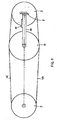
- Figure 1 schematically shows a transmission system 1, comprising a drive wheel 2 and a driven wheel 3, coupled to a drive chain 4.
- the transmission system 1 can be part of a bicycle, wherein the drive wheel 2 is driven by a user by means of pedals, but this is not shown in the figure for sake of simplicity. It is common practice that the drive wheel 2 then has a larger diameter than the driven wheel 3.
- the chain 4 successively comprises a first part 4A extending along a part of the drive wheel 2, a second part 4B extending along a part of the driven wheel 3, a third part 4C extending between the wheels 2 and 3, and a fourth part 4D extending between the wheels 2 and 3.
- first and second chain half respectively.
- the wheels 2 and 3 are rotatably mounted to a frame 5, in such a way that in rest there is a bias tension in the chain 4.
- the tension in the first chain half 4C is referred to as F c
- the tension in the second chain half 4D is referred to as F D .
- the transmission system 1 is provided with a measuring system 6, adapted for measuring the forces F C en F D in the chain 4, which are a measure for the torque transmitted by the chain 4.
- This measuring system 6 comprises a transverse force measuring wheel 10, arranged within the span of the chain 4, substantially in the same plane as the wheels 2 and 3. The diameter thereof is so large that both the first chain half 4C and the second chain half 4D follow a curved trajectory between the wheels 2 and 3, and extend for a part along the periphery of the measuring wheel 10.
- the measuring wheel 10 has the same diameter as the largest of the wheels 2 and 3, and, in case of a measuring wheel provided with sprockets, the measuring wheel can be equal to the largest of the wheels 2 and 3.
- a first transverse force F DC is exerted to the measuring wheel 10 by the tension F C in the first chain half 4C
- a second transverse force F DD is exerted to the measuring wheel 10 by the tension F D in the second chain half 4D.
- the measuring wheel 10 is rotatably mounted to a supporting arm 20, which in turn is fixed with respect to the frame.
- the centre point of the measuring wheel 10 in rest is located on a line L connecting the rotation centre points of the wheels 2 and 3. Fixation of that supporting arm 20 takes place when the system is in rest, i.e. when no drive force is exerted. Then the tensions F C en F D in the two chain halves 4C and 4D are equal to each other, and the resultant F DR of the two transverse forces F DC and F DD lies in the horizontal plane, represented in the figure by said line L. The centre of the measuring wheel 10 is then situated, as said, on said line L. In this situation the supporting arm 20 is fixed to the frame.
- the electric measurement signal S M given by the measuring sensor 30 is a measure for the force exerted, and is supplied to a processor 40 for further processing.
- this processor 40 can for instance be adapted for calculating the amount of calories consumed.
- the rotatable measuring wheel 10 is mounted on the supporting arm 20 by means of a bearing which is not shown for the sake of simplicity.
- This can be a relatively simple bearing, since the measuring wheel 10 does not experience a large force with respect to the supporting arm 20: this bearing is only loaded by the resultant F DR .
- the measuring wheel 10 is rotatable, this is not necessary for the operation of the measuring wheel 10 within the scope of the present invention. If the measuring wheel 10 is fixed, and the chain 4 slides over the measuring wheel 10, a force resultant F DR as described above emerges as well.
- a non-rotatable force sensor 10 it does not need to have a circular outline.
- the force sensor 10 can then for instance have a four-sided outline, of which two contact faces 11 and 12 situated opposite each other can have a convex shape, for instance the shape of an arc, and of which the other sides 13 and 14 can have an arbitrary shape, for instance a straight shape, as illustrated in figure 3 .
- said contact faces 11 and 12 situated opposite each other may also have a curvature radius varying as function of the location, and they can for instance have the shape of a sinusoid or hyperboloid.
- the force sensor 10 is made of a material which counteracts sound production, at least that part of the force sensor which comes into contact with the chain is provided with such a layer.
- a suitable material is synthetic material.
- the supporting arm 20 can in principle have an arbitrary direction.
- the supporting arm 20 is situated in the plane of the chain wheels 2 and 3 and the chain 4, substantially directed horizontally, i.e. perpendicular to the wheel axle connection line L.
- the deformation occurring in the supporting arm 20 as a result of the force component F V to be measured will mainly be a change of length, and the deformation sensor 30 needs to be adapted for measuring change of length, as will be clear to a person skilled in the art.
- the supporting arm 20 is situated perpendicular to the plane of the chain wheels 2 and 3 and the chain 4.
- the deformation occurring in the supporting arm 20 as a result of the force component F V to be measured will mainly be a bending, and the deformation sensor 30 needs to be adapted for measuring bending, as will be clear to a person skilled in the art.
- the supporting arm 20 is situated in the plane of the chain wheels 2 and 3 and the chain 4, substantially directed horizontally, i.e. directed according to the wheel axle connection line L.
- the deformation occurring in the supporting arm 20 as a result of the force component F V to be measured will mainly be a bending, and the deformation sensor 30 needs to be adapted for measuring bending, as will be clear to a person skilled in the art.
- This third embodiment variation is preferred.
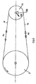
- the supporting arm 20 is not directly attached to the frame, but to the axle of the driving wheel 2 or the driven wheel 3 fixed with respect to the frame, as schematically illustrated in figure 5 .
- the advantage is achieved that, if the wheel is adjusted with respect to the frame, for instance to tighten the chain, it is not necessary to adjust the mounting of the force sensor 10 as well.
- no extra mounting point is necessary, and the measuring arrangement, when a connection bolt of the wheel is loosened, automatically seeks the position where the bending beam 20 is unloaded.
- no separate measuring wheel 10 is necessary for measuring the vertical force component Fv if the diameters of the driving wheel 2 and the driven wheel 3 are mutually different.
- the explanation given in the preceding with respect to the occurrence of a force resultant Fv is also applicable to the driving wheel 2 and the driven wheel 3: also these wheels experience a vertical force component which is a measure for the tension difference. In this case, however, this vertical force component occurs as resultant of the normal forces being exerted by the first chain part 4A and the second chain part 4B, respectively.
- This force component can be measured with a force sensor 130 associated with the wheel 2 and 3 concerned, which is schematically shown in figure 6 for the driven wheel 3.
- the known force sensors are intended for measuring the chain force itself, i.e. the tension in the first chain half 4C, based on the thought that there is no tension in the second chain half. Therefore, the known force sensors are mounted in such a way that their sensitivity direction is directed substantially horizontally, at least substantially corresponds with the direction of the first chain half 4D.
- the mounting needs to be such, that their sensitivity direction is directed substantially vertically. With respect to the known mounting, this only means a rotation over approximately 90°.
- the force sensor 10 can e.g. be provided with a groove in its surface over which the chain runs.
- the drive wheel 2 and/or the driven wheel 3 are attached to the frame 5 through a supporting arm, in a comparable way as the supporting arm 20 for the measuring wheel 10.
- a force sensor for measuring the force exerted to the measuring wheel 10 is mounted on the axle of the measuring wheel or in the bearing of the measuring wheel; for such a force sensor, a force sensor as described in WO01/30643 and/or PCT/NL02/00867 can advantageously be applied.
- the force sensor can be adapted for measuring the bending of this axle.
- the horizontal position of the measuring wheel 10 is adjustable along the said line L.
- This can for instance offer advantages in case of the measuring wheel 10 being a sprocket wheel, the sprockets of which engaging in the links of the coupling chain 4.
- Such an adjustability can be attained in a relatively easy way by providing the supporting arm 20 with a somewhat elongated hole (slotted hole), in which an attachment member for the measuring wheel 10 is fastened.
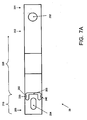
- Figure 7A shows a schematic front view of a preferred embodiment of the supporting arm 20, which in general has the shape of a beam with a rectangular cross section, wherein a first mounting hole 202 is arranged at a first end 201 for mounting the supporting arm 20 to a frame or to a bicycle axle or the like, and wherein an elongated mounting hole 204 for the measuring wheel 10 is arranged at a second end 203, the longitudinal direction of said elongated mounting hole 204 substantially overlapping with a centre line of the supporting arm 20.
- the supporting arm 20 comprises a cut-away 209 extending over almost the entire width (i.e.: vertical direction) of the arm 20, in this case a cut-away with a substantially U-shaped outline, which divides the arm 20 into a primary arm part 210 which contains the first mounting hole 202 and a secondary arm part 220 which contains the said elongated mounting hole for the measuring wheel 10.
- the cut-away 209 leaves free two bridge parts 230, 240, which connect the secondary arm part 220 with the primary arm part 210.
- Each bridge part 230, 240 has, viewed in the longitudinal direction, a first bridge end part 231, 241, a middle bridge part 232, 242, and a second bridge end part 233, 243, wherein the middle bridge part 232, 242 in the illustrated preferred embodiment is a little thicker than the adjoining first and second-bridge end parts.
- a deformation sensor 250 comprising two strain gauges 251, 252 is mounted, wherein the two strain gauges 251, 252 are ubstantially aligned with said bridge end parts 231 and 233.
- Figure 7B schematically shows a perspective view hereof.
- the side face 234 is a face of which the normal direction is substantially directed vertically, i.e. parallel to the direction of the force component F V to be measured.
- This design offers the following advantages.
- the secondary arm part 220 When a transverse force is exerted on the measuring wheel (not shown in the figures 7A and 7B ) as discussed above, the secondary arm part 220 will be displaced substantially along a straight line in a direction perpendicular to the longitudinal direction of the supporting arm 20, while the two bridge parts 230, 240 are deformed to an S-shaped outline.
- the deformation mainly occurs in the thinnest parts of the two bridge parts 230, 240, i.e. the first and second bridge end parts.
- one of the strain gauges 251, 252 experiences a lengthening while the other one experiences a shortening, and the signals generated thereby can be processed so that they enhance each other.
- the supporting arm is subjected to another deformation, like for instance a lengthening as a result of external load or as a result of temperature variations, the variations in the output signals of the measuring strips cancel each other out.
- a further advantage is attained in manufacturing the supporting arm itself.
- the bending-sensitive part of the measuring arm In order to be able to be used as measuring arm, the bending-sensitive part of the measuring arm must be manufactured precisely. In the case of a solid supporting arm, bending takes place over a relatively long length, so that the precise manufacturing must be-applied to a large' length part, which is cumbersome and makes the supporting arm relatively expensive.
- the supporting arm proposed by the present invention only a single bridge-part 230 needs to be manufactured-precisely, which is simpler.
- the elongated hole 204 and the cut-away 209 are manufactured by a single punch treatment.
- a further advantage of the supporting arm proposed by the present invention is attained when using it. Because the secondary arm part 220 is substantially displaced along a line in a direction perpendicular to the longitudinal direction of the supporting arm 20, the deformation of the bridge parts, and thereby the sensor signal generated, is substantially independent from the precise location of the axle of the measuring wheel in the elongated hole 204.
- the number of bridge parts between the primary and secondary arm parts may also be higher than two.
Landscapes
- Engineering & Computer Science (AREA)
- Chemical & Material Sciences (AREA)
- Combustion & Propulsion (AREA)
- Transportation (AREA)
- Mechanical Engineering (AREA)
- Physics & Mathematics (AREA)
- General Physics & Mathematics (AREA)
- Analytical Chemistry (AREA)
- Force Measurement Appropriate To Specific Purposes (AREA)
Claims (24)
- Système de transmission (1) comprenant :une roue d'entraînement (2), une roue menée (3) et une chaîne de couplage (4) ayant une première moitié de chaîne (4C) et une deuxième moitié de chaîne (4D) ;un dispositif de mesure de différence de tension (6) pour fournir un signal de mesure qui est représentatif du couple transmis par la chaîne de couplage (4) ;ledit dispositif de mesure (6) comprenant un capteur de force transversale (10 ; 2 ; 3), pourvu d'un moyen de mesure de force (20, 30) pour fournir un signal de mesure (SM) qui est une mesure de la composante (FV), dirigée substantiellement perpendiculairement au plan (L) défini par les axes de rotation de la roue d'entraînement (2) et de la roue menée (3), de la résultante (FDR) des forces transversales (FDC, FDD) exercées sur le capteur de force transversale (10 ; 2 ; 3) par les parties de chaîne (4C, 4D ; 4A ; 4B) ;caractérisé en ce que le capteur de force transversale (10 ; 2 ; 3) est placé dans l'intervalle d'un brin de la chaîne de couplage (4), entre la roue d'entraînement (2) et la roue menée (3), et a une première face de contact (11) qui touche le côté intérieur de la première moitié de chaîne (4C) et une deuxième face de contact (12) qui touche le côté intérieur de la deuxième moitié de chaîne (4D).
- Système de transmission selon la revendication 1, dans lequel le capteur de force transversale (10) a un contour circulaire.
- Système de transmission selon la revendication 2, dans lequel le capteur de force transversale (10) est monté de façon rotative.
- Système de transmission selon la revendication 3, dans lequel le moyen de mesure de force est monté sur un axe du capteur de force transversale (10) monté de façon rotative, ledit moyen de mesure de force comprenant de préférence un capteur sensible à la flexion dudit axe.
- Système de transmission selon la revendication 4, ledit moyen de mesure de force étant sensible à la force résultante exercée sur le capteur de force transversale (10).
- Système de transmission selon l'une quelconque des revendications 2 à 5, dans lequel le point central du capteur de force transversale (10) est substantiellement situé dans le plan (L) défini par les axes de rotation de la roue d'entraînement (2) et de la roue menée (3), et dans lequel un axe de rotation du capteur de force transversale (10) est dirigé substantiellement parallèlement aux axes de rotation de la roue d'entraînement (2) et de la roue menée (3).
- Système de transmission selon la revendication 1, dans lequel les deux faces de contact (11, 12) sont convexes avec un rayon de courbure variable.
- Système de transmission selon la revendication 1, dans lequel les deux faces de contact (11, 12) sont convexes avec un rayon de courbure qui est supérieur à la moitié de la distance entre les deux faces de contact.
- Système de transmission selon l'une quelconque des revendications 1 à 6, dans lequel ledit moyen de mesure de force est adapté pour mesurer un déplacement du capteur de force transversale (10).
- Système de transmission selon la revendication 9, dans lequel ledit dispositif de mesure comprend un bas de support pour le capteur de force transversale et ledit moyen de mesure de force comprend un capteur de mesure (30) pour mesurer une déformation du bras de support (20).
- Système de transmission selon la revendication 10, dans lequel ledit bras de support (20) est dirigé substantiellement perpendiculairement par rapport au plan (L) défini par les axes de rotation de la roue d'entraînement (2) et de la roue menée (3), et dans lequel ledit capteur de mesure (30) est adapté pour mesurer un changement de la longueur du bras de support (20).
- Système de transmission selon la revendication 10, dans lequel ledit bras de support (20) est dirigé substantiellement perpendiculairement par rapport au plan défini par la chaîne de couplage (4), et dans lequel ledit capteur de mesure (30) est adapté pour mesurer une flexion du bras de support (20).
- Système de transmission selon la revendication 10, dans lequel ledit bras de support (20) est dirigé substantiellement parallèlement au plan (L) défini par les axes de rotation de la roue d'entraînement (2) et de la roue menée (3), et est dirigé substantiellement parallèlement au plan défini par la chaîne de couplage (4), et dans lequel ledit capteur de mesure (30) est adapté pour mesurer une flexion du bras de support (20).
- Système de transmission selon la revendication 13, dans lequel ledit bras de support (20) est fixé à un axe de roue de la roue d'entraînement (2) et de la roue menée (3).
- Système de transmission selon l'une quelconque des revendications 10 à 14, dans lequel le capteur de mesure (30) comprend un ou plusieurs extensomètres.
- Système de transmission selon la revendication 1, dans lequel au moins les faces de contact (11, 12) du capteur de force transversale (10) sont fabriquées à partir d'un matériau limitant la production de bruit, dans lequel le capteur de force transversale (10) entier est de préférence fabriquée à partir d'un matériau limitant la production de bruit, ledit matériau comprenant par exemple un matériau synthétique.
- Système de transmission selon la revendication 1, dans lequel le moyen de mesure comprend un capteur de mesure (130), dans lequel le capteur de force transversale est l'une des roues (2, 3), et dans lequel le capteur de mesure (130) est adapté pour mesurer la force exercée sur la roue concernée dans une direction substantiellement perpendiculaire au plan (L) défini par les axes de rotation de la roue d'entraînement (2) et de la roue menée (3).
- Véhicule comprenant un système de transmission (1) selon l'une quelconque des revendications 1 à 17, lequel véhicule peut être un véhicule entraîné par la force humaine, en particulier une bicyclette.
- Dispositif d'entraînement, comprenant un système de transmission (1) selon l'une quelconque des revendications 1 à 17, lequel dispositif d'entraînement peut être un dispositif d'entraînement cycliste, par exemple un appareil d'entraînement cycliste ou une bicyclette d'intérieur.
- Procédé de mesure d'une force d'entraînement transmise par un système de transmission (1), comprenant une roue d'entraînement (2), une roue menée (3) et une chaîne de couplage (4) ayant une première moitié de chaîne (4C) et une deuxième moitié de chaîne (4D) ;
ledit procédé comprenant les étapes suivantes :fournir un capteur de force transversale (10) ayant une première face de contact (11) et une deuxième face de contact (12) ;mesurer la composante (FV), dirigée substantiellement perpendiculairement au plan (L) défini par les axes de rotation de la roue d'entraînement (2) et de la roue menée (3), de la résultante (FDR) des forces transversales (FDC, FDD) exercées sur le capteur de force transversale (10) par la première moitié de chaîne (4C) et la deuxième moitié de chaîne (4D) ;caractérisé par le fait de mettre en place le capteur de force transversale (10) entre la roue d'entraînement (2) et la roue menée (3), dans l'intervalle d'un brin de la chaîne de couplage (4), de telle manière que la première face de contact (11) est en contact de transmission de force avec le côté intérieur de la première moitié de chaîne (4C) et en ce que la deuxième face de contact (12) est en contact de transmission de force avec le côté intérieur de la deuxième moitié de chaîne (4D). - Procédé selon la revendication 20, dans lequel ladite composante de force (Fv) est mesurée en mesurant un déplacement du capteur de force transversale (10) provoqué par ladite composante de force (FV).
- Procédé selon la revendication 21, dans lequel le capteur de force transversale (10) est fixé avec un bras de support (20) par rapport au système de transmission (1), et dans lequel ledit déplacement est mesuré en mesurant une déformation du bras de support (20) du capteur de force transversale (10) provoquée par ladite composante de force (FV).
- Procédé selon la revendication 21, dans lequel le capteur de force transversale (10) est monté sur un axe, et dans lequel ledit déplacement est mesuré en mesurant une déformation dudit axe du capteur de force transversale (10) provoquée par ladite composante de force (FV).
- Procédé selon la revendication 21, dans lequel ledit déplacement est mesuré en mesurant une force exercée sur un roulement du capteur de force transversale (10) provoquée par ladite composante de force (FV).
Applications Claiming Priority (3)
| Application Number | Priority Date | Filing Date | Title |
|---|---|---|---|
| NL1023681A NL1023681C2 (nl) | 2003-06-17 | 2003-06-17 | Overbrengingsstelsel, en werkwijze voor het meten van een aandrijfkracht daarin. |
| NL1023765A NL1023765C1 (nl) | 2003-06-27 | 2003-06-27 | Overbrengingsstelsel, en werkwijze voor het meten van een aandrijfkracht daarin. |
| PCT/NL2004/000425 WO2004111591A1 (fr) | 2003-06-17 | 2004-06-14 | Systeme de transmission et procede de mesure de force d'entrainement |
Publications (2)
| Publication Number | Publication Date |
|---|---|
| EP1642105A1 EP1642105A1 (fr) | 2006-04-05 |
| EP1642105B1 true EP1642105B1 (fr) | 2013-03-06 |
Family
ID=33554606
Family Applications (1)
| Application Number | Title | Priority Date | Filing Date |
|---|---|---|---|
| EP04748657A Expired - Lifetime EP1642105B1 (fr) | 2003-06-17 | 2004-06-14 | Systeme de transmission et procede de mesure de force d'entrainement |
Country Status (5)
| Country | Link |
|---|---|
| US (1) | US20070099735A1 (fr) |
| EP (1) | EP1642105B1 (fr) |
| JP (1) | JP2006527853A (fr) |
| ES (1) | ES2410158T3 (fr) |
| WO (1) | WO2004111591A1 (fr) |
Families Citing this family (14)
| Publication number | Priority date | Publication date | Assignee | Title |
|---|---|---|---|---|
| US7814800B2 (en) | 2005-02-28 | 2010-10-19 | Idbike C.V. | Method and device for measuring the chain force in a bicycle |
| ATE496659T1 (de) | 2007-08-30 | 2011-02-15 | Wilson Ian John | Ergometrisches trainingsgerät |
| AT505034B1 (de) | 2007-11-08 | 2008-10-15 | Mueller Johann Dipl Ing | Messwertaufnehmer für umlaufende zugmittel |
| WO2011115633A1 (fr) | 2010-03-15 | 2011-09-22 | Motor Excellence Llc | Systèmes à flux transversal et/ou à flux commuté pour vélos électriques |
| CN103477538A (zh) | 2010-11-17 | 2013-12-25 | 电动转矩机器公司 | 具有分段定子层压件的横向和/或换向磁通系统 |
| US8854171B2 (en) | 2010-11-17 | 2014-10-07 | Electric Torque Machines Inc. | Transverse and/or commutated flux system coil concepts |
| US8952590B2 (en) | 2010-11-17 | 2015-02-10 | Electric Torque Machines Inc | Transverse and/or commutated flux systems having laminated and powdered metal portions |
| TWM412130U (en) * | 2010-12-15 | 2011-09-21 | Sevenstar Cykler Corp Ltd | Transmission detection device |
| EP3012180B1 (fr) * | 2014-10-21 | 2017-03-22 | Bhbikes Europe, S.L. | Dispositif de mesure de la force de chaîne dans un bicyclette |
| DE102015211157A1 (de) * | 2015-06-17 | 2016-12-22 | Robert Bosch Gmbh | Verfahren zur Drehmomentbestimmung in einem Riementrieb |
| EP3501961A1 (fr) | 2017-12-20 | 2019-06-26 | Specialized Bicycle Components, Inc. | Systèmes, procédés et dispositifs de détection de couple de pédalage de bicyclette |
| EP4007087B1 (fr) * | 2019-11-11 | 2024-02-07 | WEZAG GmbH & Co. KG | Pince à sertir |
| CN112649134A (zh) * | 2020-12-27 | 2021-04-13 | 湖南铭泰智能停车科技有限公司 | 一种传动承力部件拉力实时检测系统及立体停车库 |
| US20220355898A1 (en) * | 2021-05-04 | 2022-11-10 | Qingdao Choho Industrial Co.,Ltd. | Rear drive transmission system of motorcycle and motorcycle |
Family Cites Families (24)
| Publication number | Priority date | Publication date | Assignee | Title |
|---|---|---|---|---|
| SE354120B (fr) * | 1970-04-14 | 1973-02-26 | Bofors Ab | |
| US3653612A (en) * | 1970-09-21 | 1972-04-04 | Bendix Corp | Control wheel force sensor device |
| US3832899A (en) * | 1972-02-17 | 1974-09-03 | Inst Cercetare Ind Extractiva | Dynamometrical deflection measuring method and apparatus |
| US3992932A (en) * | 1974-10-24 | 1976-11-23 | Borg-Warner Corporation | Torque measuring system |
| FR2587110B1 (fr) * | 1985-09-12 | 1987-12-18 | Facom | Equilibreuse de roues et notamment de roues de vehicule automobile |
| JPH01131423A (ja) * | 1987-11-17 | 1989-05-24 | Agency Of Ind Science & Technol | 巻掛け動力伝達系のトルクセンサ |
| US4899599A (en) * | 1987-12-07 | 1990-02-13 | Magnetic Power Systems, Inc. | Strain force sensor means |
| US5445036A (en) * | 1994-06-15 | 1995-08-29 | The University Of British Columbia | Torque sensor |
| US5678678A (en) * | 1995-06-05 | 1997-10-21 | Mars Incorporated | Apparatus for measuring the profile of documents |
| GB2312193A (en) * | 1996-04-19 | 1997-10-22 | Russell John Searle | Auxiliary electric propulsion for a pedal-driven vehicle |
| JPH10176967A (ja) * | 1996-10-17 | 1998-06-30 | Hamana Buhin Kogyo Kk | 電気助力式自転車の負荷検出装置 |
| JP3671586B2 (ja) * | 1997-03-28 | 2005-07-13 | 愛知製鋼株式会社 | 回転トルクセンサ |
| WO1999029564A1 (fr) * | 1997-12-09 | 1999-06-17 | Bitz, Roland | Pedalier sans point mort, et ensemble comprenant un tel pedalier et un appareil de mesure |
| FI105666B (fi) * | 1998-02-11 | 2000-09-29 | Haloila M Oy Ab | Käärintälaite |
| JPH11258078A (ja) * | 1998-03-09 | 1999-09-24 | Toyoda Mach Works Ltd | トルク検出装置 |
| JP3771046B2 (ja) * | 1998-04-07 | 2006-04-26 | 株式会社イシダ | ロードセル式計量装置およびロードセル |
| JP2000074761A (ja) * | 1998-09-01 | 2000-03-14 | Kyoei Giken Kk | 人力補助動力装置の人力検知方法 |
| JP2000095177A (ja) * | 1998-09-22 | 2000-04-04 | Link Up:Kk | 電動駆動力補助装置 |
| JP3674755B2 (ja) * | 1999-05-11 | 2005-07-20 | 光洋精工株式会社 | プーリ荷重測定方法およびプーリ荷重測定装置 |
| NL1013338C2 (nl) | 1999-10-19 | 2001-04-23 | Idbike | Werkwijze en inrichting voor het meten van een door een fietser verrichte inspanning. |
| JP4722271B2 (ja) * | 2000-09-06 | 2011-07-13 | 株式会社ジェイテクト | トルク検出装置 |
| JP3667625B2 (ja) * | 2000-11-13 | 2005-07-06 | 住友ベークライト株式会社 | 自動車のプーリー用フェノール樹脂成形材料及び自動車用フェノール樹脂プーリー |
| US6609985B2 (en) * | 2001-11-07 | 2003-08-26 | Borgwarner Inc. | Tensioner with vibrational damping |
| NL1019636C1 (nl) | 2001-12-21 | 2003-06-24 | Idbike | Buigingssensor. |
-
2004
- 2004-06-14 US US10/560,848 patent/US20070099735A1/en not_active Abandoned
- 2004-06-14 ES ES04748657T patent/ES2410158T3/es not_active Expired - Lifetime
- 2004-06-14 EP EP04748657A patent/EP1642105B1/fr not_active Expired - Lifetime
- 2004-06-14 JP JP2006516985A patent/JP2006527853A/ja active Pending
- 2004-06-14 WO PCT/NL2004/000425 patent/WO2004111591A1/fr not_active Ceased
Also Published As
| Publication number | Publication date |
|---|---|
| JP2006527853A (ja) | 2006-12-07 |
| ES2410158T3 (es) | 2013-07-01 |
| EP1642105A1 (fr) | 2006-04-05 |
| WO2004111591A1 (fr) | 2004-12-23 |
| US20070099735A1 (en) | 2007-05-03 |
Similar Documents
| Publication | Publication Date | Title |
|---|---|---|
| EP1642105B1 (fr) | Systeme de transmission et procede de mesure de force d'entrainement | |
| EP2474343B1 (fr) | Mesure de puissance de velo a partir du pedalier | |
| US5167159A (en) | Tension transducer | |
| JP4242423B2 (ja) | ベルト動的張力計測装置および方法 | |
| EP2504177B1 (fr) | Appareil mesureur de puissance de moyeu arrière pour un vélo | |
| US5031455A (en) | Bicycle power meter | |
| ES2279773T5 (es) | Procedimiento y dispositivo para medir el esfuerzo realizado por un ciclista. | |
| NL1037563C2 (en) | Measuring device for measuring a pedalling force exerted by a cyclist. | |
| JPH0219735A (ja) | 自転車等の駆動ホイールおよびこのホイールを備える自転車 | |
| GB2463135A (en) | Cassette based power meter | |
| EP1742030B1 (fr) | Transducteur permettant de mesurer un comportement dynamique d'un arbre | |
| WO2014132021A1 (fr) | Capteur de couple de manivelle pour une bicyclette | |
| NL1023681C2 (nl) | Overbrengingsstelsel, en werkwijze voor het meten van een aandrijfkracht daarin. | |
| JP3671586B2 (ja) | 回転トルクセンサ | |
| NL1023765C1 (nl) | Overbrengingsstelsel, en werkwijze voor het meten van een aandrijfkracht daarin. | |
| US4419890A (en) | Bicycle ergometer | |
| TWI605215B (zh) | Torque sensing device of transmission system | |
| US11112322B2 (en) | Bicycle and spider capable of measuring power |
Legal Events
| Date | Code | Title | Description |
|---|---|---|---|
| PUAI | Public reference made under article 153(3) epc to a published international application that has entered the european phase |
Free format text: ORIGINAL CODE: 0009012 |
|
| 17P | Request for examination filed |
Effective date: 20060117 |
|
| AK | Designated contracting states |
Kind code of ref document: A1 Designated state(s): AT BE BG CH CY CZ DE DK EE ES FI FR GB GR HU IE IT LI LU MC NL PL PT RO SE SI SK TR |
|
| DAX | Request for extension of the european patent (deleted) | ||
| 17Q | First examination report despatched |
Effective date: 20091026 |
|
| REG | Reference to a national code |
Ref country code: DE Ref legal event code: R079 Ref document number: 602004041241 Country of ref document: DE Free format text: PREVIOUS MAIN CLASS: G01L0003140000 Ipc: B62M0006400000 |
|
| GRAP | Despatch of communication of intention to grant a patent |
Free format text: ORIGINAL CODE: EPIDOSNIGR1 |
|
| RIC1 | Information provided on ipc code assigned before grant |
Ipc: B62M 9/00 20060101ALI20120208BHEP Ipc: G01L 3/14 20060101ALI20120208BHEP Ipc: B62M 6/40 20100101AFI20120208BHEP Ipc: G01L 1/22 20060101ALI20120208BHEP Ipc: G01L 5/00 20060101ALI20120208BHEP |
|
| RAP1 | Party data changed (applicant data changed or rights of an application transferred) |
Owner name: SPINPOWER B.V. |
|
| GRAS | Grant fee paid |
Free format text: ORIGINAL CODE: EPIDOSNIGR3 |
|
| GRAA | (expected) grant |
Free format text: ORIGINAL CODE: 0009210 |
|
| AK | Designated contracting states |
Kind code of ref document: B1 Designated state(s): AT BE BG CH CY CZ DE DK EE ES FI FR GB GR HU IE IT LI LU MC NL PL PT RO SE SI SK TR |
|
| REG | Reference to a national code |
Ref country code: GB Ref legal event code: FG4D |
|
| REG | Reference to a national code |
Ref country code: CH Ref legal event code: EP Ref country code: AT Ref legal event code: REF Ref document number: 599437 Country of ref document: AT Kind code of ref document: T Effective date: 20130315 |
|
| REG | Reference to a national code |
Ref country code: IE Ref legal event code: FG4D |
|
| REG | Reference to a national code |
Ref country code: DE Ref legal event code: R096 Ref document number: 602004041241 Country of ref document: DE Effective date: 20130502 |
|
| REG | Reference to a national code |
Ref country code: NL Ref legal event code: T3 |
|
| REG | Reference to a national code |
Ref country code: ES Ref legal event code: FG2A Ref document number: 2410158 Country of ref document: ES Kind code of ref document: T3 Effective date: 20130701 |
|
| REG | Reference to a national code |
Ref country code: AT Ref legal event code: MK05 Ref document number: 599437 Country of ref document: AT Kind code of ref document: T Effective date: 20130306 |
|
| PG25 | Lapsed in a contracting state [announced via postgrant information from national office to epo] |
Ref country code: AT Free format text: LAPSE BECAUSE OF FAILURE TO SUBMIT A TRANSLATION OF THE DESCRIPTION OR TO PAY THE FEE WITHIN THE PRESCRIBED TIME-LIMIT Effective date: 20130306 Ref country code: SE Free format text: LAPSE BECAUSE OF FAILURE TO SUBMIT A TRANSLATION OF THE DESCRIPTION OR TO PAY THE FEE WITHIN THE PRESCRIBED TIME-LIMIT Effective date: 20130306 Ref country code: BG Free format text: LAPSE BECAUSE OF FAILURE TO SUBMIT A TRANSLATION OF THE DESCRIPTION OR TO PAY THE FEE WITHIN THE PRESCRIBED TIME-LIMIT Effective date: 20130606 |
|
| PG25 | Lapsed in a contracting state [announced via postgrant information from national office to epo] |
Ref country code: FI Free format text: LAPSE BECAUSE OF FAILURE TO SUBMIT A TRANSLATION OF THE DESCRIPTION OR TO PAY THE FEE WITHIN THE PRESCRIBED TIME-LIMIT Effective date: 20130306 Ref country code: GR Free format text: LAPSE BECAUSE OF FAILURE TO SUBMIT A TRANSLATION OF THE DESCRIPTION OR TO PAY THE FEE WITHIN THE PRESCRIBED TIME-LIMIT Effective date: 20130607 Ref country code: SI Free format text: LAPSE BECAUSE OF FAILURE TO SUBMIT A TRANSLATION OF THE DESCRIPTION OR TO PAY THE FEE WITHIN THE PRESCRIBED TIME-LIMIT Effective date: 20130306 |
|
| PG25 | Lapsed in a contracting state [announced via postgrant information from national office to epo] |
Ref country code: SK Free format text: LAPSE BECAUSE OF FAILURE TO SUBMIT A TRANSLATION OF THE DESCRIPTION OR TO PAY THE FEE WITHIN THE PRESCRIBED TIME-LIMIT Effective date: 20130306 Ref country code: PT Free format text: LAPSE BECAUSE OF FAILURE TO SUBMIT A TRANSLATION OF THE DESCRIPTION OR TO PAY THE FEE WITHIN THE PRESCRIBED TIME-LIMIT Effective date: 20130708 Ref country code: RO Free format text: LAPSE BECAUSE OF FAILURE TO SUBMIT A TRANSLATION OF THE DESCRIPTION OR TO PAY THE FEE WITHIN THE PRESCRIBED TIME-LIMIT Effective date: 20130306 Ref country code: EE Free format text: LAPSE BECAUSE OF FAILURE TO SUBMIT A TRANSLATION OF THE DESCRIPTION OR TO PAY THE FEE WITHIN THE PRESCRIBED TIME-LIMIT Effective date: 20130306 Ref country code: CZ Free format text: LAPSE BECAUSE OF FAILURE TO SUBMIT A TRANSLATION OF THE DESCRIPTION OR TO PAY THE FEE WITHIN THE PRESCRIBED TIME-LIMIT Effective date: 20130306 |
|
| PG25 | Lapsed in a contracting state [announced via postgrant information from national office to epo] |
Ref country code: CY Free format text: LAPSE BECAUSE OF FAILURE TO SUBMIT A TRANSLATION OF THE DESCRIPTION OR TO PAY THE FEE WITHIN THE PRESCRIBED TIME-LIMIT Effective date: 20130306 Ref country code: PL Free format text: LAPSE BECAUSE OF FAILURE TO SUBMIT A TRANSLATION OF THE DESCRIPTION OR TO PAY THE FEE WITHIN THE PRESCRIBED TIME-LIMIT Effective date: 20130306 |
|
| PLBE | No opposition filed within time limit |
Free format text: ORIGINAL CODE: 0009261 |
|
| STAA | Information on the status of an ep patent application or granted ep patent |
Free format text: STATUS: NO OPPOSITION FILED WITHIN TIME LIMIT |
|
| PG25 | Lapsed in a contracting state [announced via postgrant information from national office to epo] |
Ref country code: MC Free format text: LAPSE BECAUSE OF FAILURE TO SUBMIT A TRANSLATION OF THE DESCRIPTION OR TO PAY THE FEE WITHIN THE PRESCRIBED TIME-LIMIT Effective date: 20130306 Ref country code: DK Free format text: LAPSE BECAUSE OF FAILURE TO SUBMIT A TRANSLATION OF THE DESCRIPTION OR TO PAY THE FEE WITHIN THE PRESCRIBED TIME-LIMIT Effective date: 20130306 |
|
| 26N | No opposition filed |
Effective date: 20131209 |
|
| REG | Reference to a national code |
Ref country code: DE Ref legal event code: R097 Ref document number: 602004041241 Country of ref document: DE Effective date: 20131209 |
|
| PG25 | Lapsed in a contracting state [announced via postgrant information from national office to epo] |
Ref country code: TR Free format text: LAPSE BECAUSE OF FAILURE TO SUBMIT A TRANSLATION OF THE DESCRIPTION OR TO PAY THE FEE WITHIN THE PRESCRIBED TIME-LIMIT Effective date: 20130306 |
|
| REG | Reference to a national code |
Ref country code: FR Ref legal event code: PLFP Year of fee payment: 12 |
|
| PG25 | Lapsed in a contracting state [announced via postgrant information from national office to epo] |
Ref country code: HU Free format text: LAPSE BECAUSE OF FAILURE TO SUBMIT A TRANSLATION OF THE DESCRIPTION OR TO PAY THE FEE WITHIN THE PRESCRIBED TIME-LIMIT; INVALID AB INITIO Effective date: 20040614 |
|
| PGFP | Annual fee paid to national office [announced via postgrant information from national office to epo] |
Ref country code: GB Payment date: 20150630 Year of fee payment: 12 Ref country code: CH Payment date: 20150623 Year of fee payment: 12 Ref country code: LU Payment date: 20150625 Year of fee payment: 12 |
|
| PGFP | Annual fee paid to national office [announced via postgrant information from national office to epo] |
Ref country code: IE Payment date: 20150625 Year of fee payment: 12 Ref country code: FR Payment date: 20150630 Year of fee payment: 12 Ref country code: BE Payment date: 20150617 Year of fee payment: 12 Ref country code: NL Payment date: 20150617 Year of fee payment: 12 |
|
| PGFP | Annual fee paid to national office [announced via postgrant information from national office to epo] |
Ref country code: DE Payment date: 20150831 Year of fee payment: 12 Ref country code: ES Payment date: 20150722 Year of fee payment: 12 |
|
| PGFP | Annual fee paid to national office [announced via postgrant information from national office to epo] |
Ref country code: IT Payment date: 20150629 Year of fee payment: 12 |
|
| PG25 | Lapsed in a contracting state [announced via postgrant information from national office to epo] |
Ref country code: BE Free format text: LAPSE BECAUSE OF NON-PAYMENT OF DUE FEES Effective date: 20160630 |
|
| REG | Reference to a national code |
Ref country code: DE Ref legal event code: R119 Ref document number: 602004041241 Country of ref document: DE |
|
| PG25 | Lapsed in a contracting state [announced via postgrant information from national office to epo] |
Ref country code: LU Free format text: LAPSE BECAUSE OF NON-PAYMENT OF DUE FEES Effective date: 20160614 |
|
| REG | Reference to a national code |
Ref country code: CH Ref legal event code: PL |
|
| REG | Reference to a national code |
Ref country code: NL Ref legal event code: MM Effective date: 20160701 |
|
| GBPC | Gb: european patent ceased through non-payment of renewal fee |
Effective date: 20160614 |
|
| REG | Reference to a national code |
Ref country code: IE Ref legal event code: MM4A |
|
| REG | Reference to a national code |
Ref country code: FR Ref legal event code: ST Effective date: 20170228 |
|
| PG25 | Lapsed in a contracting state [announced via postgrant information from national office to epo] |
Ref country code: FR Free format text: LAPSE BECAUSE OF NON-PAYMENT OF DUE FEES Effective date: 20160630 Ref country code: LI Free format text: LAPSE BECAUSE OF NON-PAYMENT OF DUE FEES Effective date: 20160630 Ref country code: DE Free format text: LAPSE BECAUSE OF NON-PAYMENT OF DUE FEES Effective date: 20170103 Ref country code: CH Free format text: LAPSE BECAUSE OF NON-PAYMENT OF DUE FEES Effective date: 20160630 |
|
| PG25 | Lapsed in a contracting state [announced via postgrant information from national office to epo] |
Ref country code: IE Free format text: LAPSE BECAUSE OF NON-PAYMENT OF DUE FEES Effective date: 20160614 Ref country code: GB Free format text: LAPSE BECAUSE OF NON-PAYMENT OF DUE FEES Effective date: 20160614 Ref country code: NL Free format text: LAPSE BECAUSE OF NON-PAYMENT OF DUE FEES Effective date: 20160701 |
|
| PG25 | Lapsed in a contracting state [announced via postgrant information from national office to epo] |
Ref country code: IT Free format text: LAPSE BECAUSE OF NON-PAYMENT OF DUE FEES Effective date: 20160614 |
|
| PG25 | Lapsed in a contracting state [announced via postgrant information from national office to epo] |
Ref country code: ES Free format text: LAPSE BECAUSE OF NON-PAYMENT OF DUE FEES Effective date: 20160615 |
|
| REG | Reference to a national code |
Ref country code: ES Ref legal event code: FD2A Effective date: 20181203 |