EP1643135A2 - Pompe à liquide - Google Patents
Pompe à liquide Download PDFInfo
- Publication number
- EP1643135A2 EP1643135A2 EP05021253A EP05021253A EP1643135A2 EP 1643135 A2 EP1643135 A2 EP 1643135A2 EP 05021253 A EP05021253 A EP 05021253A EP 05021253 A EP05021253 A EP 05021253A EP 1643135 A2 EP1643135 A2 EP 1643135A2
- Authority
- EP
- European Patent Office
- Prior art keywords
- pump
- chamber
- rotor chamber
- rotor
- pump according
- Prior art date
- Legal status (The legal status is an assumption and is not a legal conclusion. Google has not performed a legal analysis and makes no representation as to the accuracy of the status listed.)
- Withdrawn
Links
- 239000007788 liquid Substances 0.000 title claims abstract description 25
- 238000005192 partition Methods 0.000 claims abstract description 22
- 239000012530 fluid Substances 0.000 claims abstract description 11
- 238000005406 washing Methods 0.000 claims abstract description 5
- 230000001419 dependent effect Effects 0.000 claims description 8
- XLYOFNOQVPJJNP-UHFFFAOYSA-N water Substances O XLYOFNOQVPJJNP-UHFFFAOYSA-N 0.000 description 7
- 238000011161 development Methods 0.000 description 5
- 230000018109 developmental process Effects 0.000 description 5
- 230000008901 benefit Effects 0.000 description 4
- 238000001816 cooling Methods 0.000 description 4
- 230000007246 mechanism Effects 0.000 description 4
- 238000011010 flushing procedure Methods 0.000 description 3
- 238000013022 venting Methods 0.000 description 3
- 239000002918 waste heat Substances 0.000 description 3
- 238000013461 design Methods 0.000 description 2
- 238000010438 heat treatment Methods 0.000 description 2
- 238000005086 pumping Methods 0.000 description 2
- 238000012546 transfer Methods 0.000 description 2
- 230000007704 transition Effects 0.000 description 2
- 230000004888 barrier function Effects 0.000 description 1
- 230000015572 biosynthetic process Effects 0.000 description 1
- 238000004891 communication Methods 0.000 description 1
- 238000011109 contamination Methods 0.000 description 1
- 239000000110 cooling liquid Substances 0.000 description 1
- 239000007789 gas Substances 0.000 description 1
- 230000012447 hatching Effects 0.000 description 1
- 238000009413 insulation Methods 0.000 description 1
- 238000004519 manufacturing process Methods 0.000 description 1
- 239000002184 metal Substances 0.000 description 1
- 238000000034 method Methods 0.000 description 1
- 238000010926 purge Methods 0.000 description 1
- 238000007493 shaping process Methods 0.000 description 1
- 230000036962 time dependent Effects 0.000 description 1
Images

Classifications
-
- F—MECHANICAL ENGINEERING; LIGHTING; HEATING; WEAPONS; BLASTING
- F04—POSITIVE - DISPLACEMENT MACHINES FOR LIQUIDS; PUMPS FOR LIQUIDS OR ELASTIC FLUIDS
- F04D—NON-POSITIVE-DISPLACEMENT PUMPS
- F04D13/00—Pumping installations or systems
- F04D13/02—Units comprising pumps and their driving means
- F04D13/06—Units comprising pumps and their driving means the pump being electrically driven
-
- F—MECHANICAL ENGINEERING; LIGHTING; HEATING; WEAPONS; BLASTING
- F04—POSITIVE - DISPLACEMENT MACHINES FOR LIQUIDS; PUMPS FOR LIQUIDS OR ELASTIC FLUIDS
- F04D—NON-POSITIVE-DISPLACEMENT PUMPS
- F04D29/00—Details, component parts, or accessories
- F04D29/58—Cooling; Heating; Diminishing heat transfer
- F04D29/586—Cooling; Heating; Diminishing heat transfer specially adapted for liquid pumps
- F04D29/588—Cooling; Heating; Diminishing heat transfer specially adapted for liquid pumps cooling or heating the machine
Definitions
- the invention relates to a liquid pump according to the preamble of claim 1.
- Liquid pumps in particular for domestic appliances, dishwashers, washing machines or the like, are already commercially available in so-called wet-rotor versions.
- the rotor of the motor is housed in a rotor chamber whose housing wall separates the stator liquid-tight from the rotor.
- the rotor chamber is in this case liquid-permeable connected to the pump chamber within the pump housing, so that a liquid or water exchange takes place.
- the housing of the rotor chamber is often referred to as a can, because it extends through the annular gap between the rotor and stator.
- the object of the invention is in contrast to propose a liquid pump which avoids the disadvantages mentioned above while maintaining the advantages of a wet rotor or at least reduced.
- a liquid pump according to the invention is characterized in that a heat-conducting partition between the pump chamber and the rotor chamber is provided.
- an at least temporarily liquid-tight partition between the pump chamber and the rotor chamber is provided. This leads at least in the closed time intervals to a complete decoupling of the rotor chamber from the pump chamber and thus from the liquid circuit during operation of the pump. Contamination via the liquid circuit is therefore completely excluded on the rotor chamber side.
- the advantages of the wet rotor, ie a good cooling of the engine and the use of waste heat is ensured by the heat-conducting formation of the partition.
- a surface-enlarging structure for the partition wall is preferably provided.
- Such a surface-enlarging structure could be obtained, for example, by appropriate shaping, i. in the form of grooves, zig-zag profiles or the like.
- the attachment of ribs or the like in the region of the transition point between the rotor chamber and pump chamber would be conceivable.
- theressbehellung the rotor chamber is provided during commissioning of the pump.
- the partition is preferably a passage provided in the partition through which this filling is to be made.
- a valve for the rotor chamber is provided to allow the filling of the rotor chamber and at the same time a liquid-tight seal between the rotor chamber and the pump chamber during operation.
- Such a valve can open a passage for purposes of filling and reseal during operation.
- vent valve for the rotor chamber to allow filling, e.g. during initial start-up or to facilitate unwanted emptying of the rotor chamber.
- a vent valve cooperate with a correspondingly small and suitably arranged open filling opening in such a way that a Nachbow to liquid takes place only with simultaneous removal of air through the vent valve.
- the filling valve for the rotor chamber is formed in an advantageous embodiment as a float, so that an automatic venting and refilling of the rotor chamber via the pump circuit is possible.
- a controlled filling of the rotor chamber with liquid, such as water, is provided via the pump circuit.
- liquid such as water
- control may depend on various parameters be made.
- the control for example via an automatic valve or even via a controlled valve can be made.
- the valve can be formed, for example electromagnetically, mechanically or hydraulically controlled.
- the filling of the rotor chamber is controlled in a particular embodiment of the invention depending on the presence of air in the rotor chamber.
- This can be like o.a. for example via an automatic venting valve in communication, e.g. with a float valve, are made in the partition between the rotor chamber and pump chamber without external control.
- a controlled air-dependent refilling by means of an air sensor e.g. a float, a light barrier or the like would be conceivable.
- the rotor chamber is filled depending on the temperature.
- the use of a valve would be possible, for example, includes a thermostat and so when exceeding a threshold temperature in the rotor chamber allows the passage of liquid into the rotor chamber. Accordingly, e.g. due to leaks, the rotor chamber empties, so that sufficient cooling is no longer guaranteed, the temperature rises accordingly there until a filling with liquid via the pump circuit.
- a temperature-dependent filling would also be conceivable in another embodiment with a temperature sensor and an external control of a corresponding filling valve.
- a filling of the rotor chamber is provided depending on the direction of rotation of the drive motor.
- the axial force exerted by a corresponding impeller on the axle could be used to open or close a passage between the pump chamber and the rotor chamber.
- a corresponding motor control could be provided, which initiates the filling of the rotor chamber depending on corresponding state parameters.
- the axial force can be e.g. produce by a corresponding angular position of the wings of the impeller.
- the filling of the rotor chamber can also be made time-dependent, i. it may be provided at certain time intervals, an opening of the passage between the rotor chamber and the pump chamber to ensure that the rotor chamber is always sufficiently filled with liquid.
- Essential to the invention is compared to the usual wet-running pumps the fact that at least partially the required heat transfer between the rotor chamber and pump chamber on the heat-conducting function of the partition is accomplished and thus the fluid exchange between the pump chamber and rotor chamber can be reduced or avoided altogether.
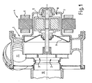
- FIG. 1 schematically shows a liquid pump or a so-called "wet rotor” for a dishwasher with an inlet 10 and a drain 11.
- the wet rotor has a pump housing 1, in which a pump chamber 2 is provided with a pump impeller 3, and a motor 4 with a rotor 5 and a stator 6.
- the stator 6 is separated from a rotor chamber 8 by means of a wall 7.
- a heat-conducting partition wall 9, in particular a metal wall 9 is provided between the pump chamber 2 and the rotor chamber 8.
- heat of the rotor chamber 8 or a fluid provided in this, in particular cooling liquid in an advantageous manner in the pump chamber 2 and in a pumping fluid, in particular water, are derived.
- a cooling of the motor 4 is realized according to the invention, without possibly polluted pumping fluid or washing water can get into the rotor chamber 8.
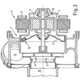
- FIG. 2 shows a variant with a float 12 for venting the rotor chamber 8.
- the drain 11 is arranged at the top in the vertical direction.
- the float 12 comprises an opening through which any gas present in the rotor chamber 8, in particular air, can escape.
- the partition wall 9 or the pump housing 1 may comprise the opening of the float 12 in an advantageous manner.
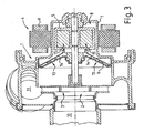
- FIG. 3 shows a variant with a direction-dependent flushing of the rotor chamber 8.
- the partition wall 9 at least one valve 13 with openings which can be opened or closed by means of a lever mechanism 14.
- the mechanism 14 includes a spring.
- the closing or opening of the valve 13 is achieved by changing the direction of rotation of the motor 4 in that the impeller 3 generates an axially aligned force by an advantageous embodiment of the blades.
- This force in turn causes a relative movement 15 between the partition 9 and rotor 5, so that the volume of the rotor chamber 8 and the pressure in this changes.
- the mechanism 13 opens or closes the openings of the partition wall 9. When the opening is open, an advantageous replacement of the fluid of the rotor chamber 8 can take place.
- the variant of Figure 4 also has a direction-dependent flushing.
- the partition wall 9 at least a comparatively large opening 16 which can be opened or closed by means of a paddle 17 or the like.
- the paddle 17 is adjusted in a first or in a second position due to the present in the rotor chamber 8 flow of the fluid.
- FIG. 4b a section in the region of the paddle 17 is shown schematically in the cutout.
- the opening 16 In the first position (solid line) the opening 16 is open.
- the opening 16 In the second position (hatching), the opening 16 is closed by the paddle 17.
Landscapes
- Engineering & Computer Science (AREA)
- Mechanical Engineering (AREA)
- General Engineering & Computer Science (AREA)
- Physics & Mathematics (AREA)
- Thermal Sciences (AREA)
- Structures Of Non-Positive Displacement Pumps (AREA)
Applications Claiming Priority (1)
| Application Number | Priority Date | Filing Date | Title |
|---|---|---|---|
| DE102004048557A DE102004048557A1 (de) | 2004-10-04 | 2004-10-04 | Flüssigkeitspumpe |
Publications (1)
| Publication Number | Publication Date |
|---|---|
| EP1643135A2 true EP1643135A2 (fr) | 2006-04-05 |
Family
ID=35079130
Family Applications (1)
| Application Number | Title | Priority Date | Filing Date |
|---|---|---|---|
| EP05021253A Withdrawn EP1643135A2 (fr) | 2004-10-04 | 2005-09-29 | Pompe à liquide |
Country Status (3)
| Country | Link |
|---|---|
| US (1) | US20060093502A1 (fr) |
| EP (1) | EP1643135A2 (fr) |
| DE (1) | DE102004048557A1 (fr) |
Families Citing this family (6)
| Publication number | Priority date | Publication date | Assignee | Title |
|---|---|---|---|---|
| TWI363141B (en) * | 2006-01-11 | 2012-05-01 | Delta Electronics Inc | Water pump and bearing thereof |
| EP2091133B1 (fr) * | 2008-02-13 | 2012-08-15 | Askoll Holding S.r.l. | Moteur électrique et pompe électrique |
| DE102011121149A1 (de) * | 2011-12-15 | 2013-06-20 | Wilo Se | Nassläuferpumpe mit Vorkammer |
| DE102012206189A1 (de) * | 2012-04-16 | 2013-10-17 | Robert Bosch Gmbh | Elektrische Maschine und Verfahren zum Betreiben einer elektrischen Maschine |
| DE102014109625A1 (de) * | 2014-07-09 | 2016-01-14 | Hanning Elektro-Werke Gmbh & Co. Kg | Pumpenanordnung |
| DE102017112890A1 (de) * | 2017-06-12 | 2018-12-13 | Hanning Elektro-Werke Gmbh & Co. Kg | Pumpenanordnung |
Family Cites Families (9)
| Publication number | Priority date | Publication date | Assignee | Title |
|---|---|---|---|---|
| US3395644A (en) * | 1966-06-16 | 1968-08-06 | Sta Rite Products Inc | Motor pump unit |
| DE2639541A1 (de) * | 1976-09-02 | 1978-03-09 | Grundfos As | Umwaelzpumpe fuer insbesondere heizungs- und brauchwasseranlagen |
| FR2508563B1 (fr) * | 1981-06-26 | 1985-11-08 | Electro Hydraulique Seh | Motopompe a moteur electrique a rotor noye |
| DE3220448C1 (de) * | 1982-05-29 | 1983-08-11 | Grundfos A/S, 8850 Bjerringbro | Pumpenaggregat fuer Heizungs- und Brauchwasseranlagen |
| DE3843477A1 (de) * | 1988-12-23 | 1990-06-28 | Oplaender Wilo Werk Gmbh | Spaltrohr-elektromotor |
| DE9302945U1 (de) * | 1993-03-01 | 1993-11-11 | Hanning Elektro-Werke GmbH & Co, 33813 Oerlinghausen | Mit einer Anlaufhilfe ausgestatteter Synchronmotor |
| KR100198399B1 (ko) * | 1996-11-29 | 1999-06-15 | 전주범 | 온수순환펌프용 수중회전 로터구조 |
| DE19721196A1 (de) * | 1997-05-21 | 1998-11-26 | Klein Schanzlin & Becker Ag | Maschinenaggregat mit integrierter Wärmesperre |
| DE19914581A1 (de) * | 1999-03-31 | 2000-10-12 | Grundfos A S Bjerringbro | Kreiselpumpenaggregat |
-
2004
- 2004-10-04 DE DE102004048557A patent/DE102004048557A1/de not_active Withdrawn
-
2005
- 2005-09-29 EP EP05021253A patent/EP1643135A2/fr not_active Withdrawn
- 2005-10-04 US US11/241,922 patent/US20060093502A1/en not_active Abandoned
Also Published As
| Publication number | Publication date |
|---|---|
| DE102004048557A1 (de) | 2006-04-06 |
| US20060093502A1 (en) | 2006-05-04 |
Similar Documents
| Publication | Publication Date | Title |
|---|---|---|
| DE10207653C1 (de) | Elektrische Kühlmittelpumpe mit integriertem Ventil, sowie Verfahren zu dessen Steuerung | |
| EP1870508B1 (fr) | Pompe, en particulier pour machines domestiques utilisant de l' eau | |
| DE19809123B4 (de) | Wasserpumpe für den Kühlkreislauf einer Brennkraftmaschine | |
| DE112017002570B4 (de) | Strömungsdurchgangsumschaltventil | |
| DE102008051145C5 (de) | Nockenwellenversteller mit Riemenantrieb | |
| DE102007011669A1 (de) | Pumpvorrichtung und Servolenkung | |
| WO2015070955A1 (fr) | Pompe à réfrigérant électromotrice | |
| DE102013203715B4 (de) | Kompakte Getriebefluid-Heizvorrichtung | |
| DE102008050895A1 (de) | Pumpe für Fluide | |
| DE10356855A1 (de) | Kraftstoffzufuhreinheit | |
| EP3267042A1 (fr) | Groupe motopompe | |
| EP1643135A2 (fr) | Pompe à liquide | |
| EP0874201B2 (fr) | Ensemble pour installation de chauffage compact | |
| EP3540234A1 (fr) | Groupe pompe centrifuge et procédé pour déplacer une valve dans un groupe pompe centrifuge | |
| WO2013079348A2 (fr) | Filtre et appareil électroménager à circulation d'eau | |
| DE10111739A1 (de) | Pumpaggregat | |
| DE4143492C2 (de) | Pumpenaggregat | |
| DE102012200113B4 (de) | Heizeinrichtung in einem wasserführenden Haushaltsgerät | |
| EP1291207B1 (fr) | Dispositif de chauffage, notamment pour véhicules | |
| DE102007062013B4 (de) | Vorrichtung zum Bügeln | |
| DE3601089A1 (de) | Fluessigkeitsgekuehlte elektromaschine | |
| WO2023280555A1 (fr) | Système d'approvisionnement en agent de refroidissement pour un dispositif d'entraînement d'un véhicule électrique | |
| DE10326730A1 (de) | Hybridkompressorsystem | |
| DE602005006051T2 (de) | Kraftstoffpumpe | |
| DE102019117521A1 (de) | Verfahren zum Erwärmen von Hydraulikflüssigkeit in einem Hydraulikkreislauf eines Kraftfahrzeugs sowie Baugruppe |
Legal Events
| Date | Code | Title | Description |
|---|---|---|---|
| PUAI | Public reference made under article 153(3) epc to a published international application that has entered the european phase |
Free format text: ORIGINAL CODE: 0009012 |
|
| AK | Designated contracting states |
Kind code of ref document: A2 Designated state(s): AT BE BG CH CY CZ DE DK EE ES FI FR GB GR HU IE IS IT LI LT LU LV MC NL PL PT RO SE SI SK TR |
|
| AX | Request for extension of the european patent |
Extension state: AL BA HR MK YU |
|
| STAA | Information on the status of an ep patent application or granted ep patent |
Free format text: STATUS: THE APPLICATION HAS BEEN WITHDRAWN |
|
| 18W | Application withdrawn |
Effective date: 20080910 |