EP1643316A2 - Bilderzeugungsgerät - Google Patents
Bilderzeugungsgerät Download PDFInfo
- Publication number
- EP1643316A2 EP1643316A2 EP05021198A EP05021198A EP1643316A2 EP 1643316 A2 EP1643316 A2 EP 1643316A2 EP 05021198 A EP05021198 A EP 05021198A EP 05021198 A EP05021198 A EP 05021198A EP 1643316 A2 EP1643316 A2 EP 1643316A2
- Authority
- EP
- European Patent Office
- Prior art keywords
- image
- paper
- sheet
- intermediate transfer
- image forming
- Prior art date
- Legal status (The legal status is an assumption and is not a legal conclusion. Google has not performed a legal analysis and makes no representation as to the accuracy of the status listed.)
- Granted
Links
Images

Classifications
-
- G—PHYSICS
- G03—PHOTOGRAPHY; CINEMATOGRAPHY; ANALOGOUS TECHNIQUES USING WAVES OTHER THAN OPTICAL WAVES; ELECTROGRAPHY; HOLOGRAPHY
- G03G—ELECTROGRAPHY; ELECTROPHOTOGRAPHY; MAGNETOGRAPHY
- G03G15/00—Apparatus for electrographic processes using a charge pattern
- G03G15/22—Apparatus for electrographic processes using a charge pattern involving the combination of more than one step according to groups G03G13/02 - G03G13/20
- G03G15/23—Apparatus for electrographic processes using a charge pattern involving the combination of more than one step according to groups G03G13/02 - G03G13/20 specially adapted for copying both sides of an original or for copying on both sides of a recording or image-receiving material
- G03G15/231—Arrangements for copying on both sides of a recording or image-receiving material
- G03G15/232—Arrangements for copying on both sides of a recording or image-receiving material using a single reusable electrographic recording member
- G03G15/234—Arrangements for copying on both sides of a recording or image-receiving material using a single reusable electrographic recording member by inverting and refeeding the image receiving material with an image on one face to the recording member to transfer a second image on its second face, e.g. by using a duplex tray; Details of duplex trays or inverters
-
- G—PHYSICS
- G03—PHOTOGRAPHY; CINEMATOGRAPHY; ANALOGOUS TECHNIQUES USING WAVES OTHER THAN OPTICAL WAVES; ELECTROGRAPHY; HOLOGRAPHY
- G03G—ELECTROGRAPHY; ELECTROPHOTOGRAPHY; MAGNETOGRAPHY
- G03G7/00—Selection of materials for use in image-receiving members, i.e. for reversal by physical contact; Manufacture thereof
- G03G7/006—Substrates for image-receiving members; Image-receiving members comprising only one layer
- G03G7/0066—Inorganic components thereof
-
- G—PHYSICS
- G03—PHOTOGRAPHY; CINEMATOGRAPHY; ANALOGOUS TECHNIQUES USING WAVES OTHER THAN OPTICAL WAVES; ELECTROGRAPHY; HOLOGRAPHY
- G03G—ELECTROGRAPHY; ELECTROPHOTOGRAPHY; MAGNETOGRAPHY
- G03G7/00—Selection of materials for use in image-receiving members, i.e. for reversal by physical contact; Manufacture thereof
- G03G7/006—Substrates for image-receiving members; Image-receiving members comprising only one layer
- G03G7/0073—Organic components thereof
-
- G—PHYSICS
- G03—PHOTOGRAPHY; CINEMATOGRAPHY; ANALOGOUS TECHNIQUES USING WAVES OTHER THAN OPTICAL WAVES; ELECTROGRAPHY; HOLOGRAPHY
- G03G—ELECTROGRAPHY; ELECTROPHOTOGRAPHY; MAGNETOGRAPHY
- G03G2215/00—Apparatus for electrophotographic processes
- G03G2215/01—Apparatus for electrophotographic processes for producing multicoloured copies
- G03G2215/0167—Apparatus for electrophotographic processes for producing multicoloured copies single electrographic recording member
- G03G2215/0174—Apparatus for electrophotographic processes for producing multicoloured copies single electrographic recording member plural rotations of recording member to produce multicoloured copy
- G03G2215/0177—Rotating set of developing units
Definitions
- the present invention relates to an image forming apparatus capable of forming a monochrome (monochromatic) image or a color image on both sides of a paper (a plain paper, a cardboard, a postcard, an envelope, an OHP sheet or other sheet-shaped recording media).
- a paper a plain paper, a cardboard, a postcard, an envelope, an OHP sheet or other sheet-shaped recording media.
- the invention relates to a technique regarding the return speed of a paper in the case that images are formed on both sides of the paper.
- an image forming apparatus including an image forming portion for forming an image having one color on an intermediate transfer member per rotation of the intermediate transfer member or superposing images having a plurality of colors on the intermediate transfer member by a plurality of rotations of the intermediate transfer member, thereby forming a color image on the intermediate transfer member, a transfer portion for transferring the image formed on the intermediate transfer member in the image forming portion to a paper, and a fixing portion for causing the paper having the image transferred in the transfer portion to pass therethrough, thereby fixing the image onto the paper, in which the paper passing through the fixing portion can be switched back toward a return path and can be thus returned to the transfer portion so that the image can also be transferred to the other surface of the paper, a paper return speed in the formation of a color image is also increased if all of the delivery speeds of the paper except for the time of the transfer of the image are increased as in the prior art described above.
- an image forming apparatus comprising:
- the image forming portion forms an image having one color on the intermediate transfer member per rotation of the intermediate transfer member.
- the sheet is returned through the return path at a return speed greater than the delivery speed of the sheet at the transfer in the transfer portion when the image formed in the image forming portion for the second face of the sheet is a one color image.
- the sheet when the image to be formed in the image forming portion for the second face of the sheet is a color image, the sheet is returned at a low speed which is equal to or lower than the delivery speed in the transfer. Therefore, a noise made by returning the sheet can be reduced.
- an image forming apparatus having such a structure as to form the image having one color on the intermediate transfer member per rotation of the intermediate transfer member in the formation of a color image and to superpose images having a plurality of colors on the intermediate transfer member by a plurality of rotations of the intermediate transfer member, thereby forming color images on the intermediate transfer member, and to transfer the color images to the sheet in a lump in the transfer portion, even if the sheet is returned at a high speed, the image cannot be transferred before the superposition of the color image is completed. For this reason, the return at an unnecessarily high speed is useless, resulting in an increase in a noise.
- the image forming apparatus in accordance with the invention when a color image is formed in the image forming portion for the second face of the sheet, the sheet is returned at a low speed which is equal to or less than the delivery speed in the transfer. Consequently, it is possible to reduce a noise which is made by the return of the sheet.
- the return speed of the sheet is set to be equal to a speed at which a tip of the sheet in a delivery of the sheet reaches the transfer portion at the transferring timing in which the color image is transferred to the second face of the sheet in the transfer portion.
- the image to be formed in the image forming portion for the second face of the sheet is a monochrome image (the one image)
- the sheet is returned at a higher speed than the delivery speed in the transfer. Consequently, it is possible to increase the number of the sheets on which the monochrome image is formed per unit time.
- Fig. 1 is a schematic front view showing an internal structure of the image forming apparatus according to the embodiment of the invention.
- the image forming apparatus can send a paper having an A4 size (including a letter size) longitudinally to form a monochrome (monochromatic) image or a full color image on both sides thereof, and includes a case 11, an image carrier unit 20 accommodated in the case 11 and constituting an image forming portion, an exposing unit 30, and a developing unit (a developing device) 40. Moreover, the image forming apparatus includes an intermediate transfer unit 50 and a fixing unit (fixing portion) 60.
- the case 11 is provided with a frame (not shown) in an apparatus body 10, and each unit is attached to the frame.
- the image carrier unit 20 includes a photosensitive member 21 having a photosensitive layer on an outer peripheral surface, and a corona charger (a scorotron charger) 22 serving as a charging unit for uniformly charging the outer peripheral surface of the photosensitive member 21, and the outer peripheral surface of the photosensitive member 21 which is uniformly charged by the corona charger 22 is selectively exposed by a laser beam L emitted from the exposing unit 30 to form an electrostatic latent image and a toner to be a developer is applied to the electrostatic latent image by means of the developing unit 40 to form a visible image (a toner image), and the toner image is a primarily transferred in a primary transfer portion T1 to an intermediate transfer belt 51 serving as the intermediate transfer member of the intermediate transfer unit 50, and furthermore, is secondarily transferred to the paper serving as a transfer object in a secondary transfer portion (transfer portion) T2.
- a corona charger a scorotron charger 22 serving as a charging unit for uniformly charging the outer peripheral surface of the photosensitive member 21, and the outer
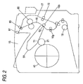
- the case 11 includes a delivery path 16 for delivering the paper having an image formed on either side by the secondary transfer portion T2 toward a paper discharge portion (a paper discharge tray) 15 on the upper surface of the case 11, and a return path 17 for switching back the paper delivered toward the paper discharge portion 15 through the delivery path 16 and returning the paper toward the secondary transfer portion T2 in order to form an image on the other surface.
- the double-sided unit 70 denotes a double-sided unit which is constituted to be freely attached to or removed from an apparatus body, and the double-sided unit 70 is attached so that the return path 17 is finished.
- 71 denotes a driving motor for returning a paper
- 72 denotes a paper return roller to be driven by the motor 71 through a driving mechanism (not shown) such as a timing belt.
- a paper feed cassette 18 for laminating and holding a plurality of papers is provided in the lower part of the case 11, and a paper feed roller 19 for feeding the papers one by one toward the secondary transfer portion T2 is provided.
- a multipurpose tray 81 constituting a manual paper feed portion 80 is provided below the double-sided unit 70, and the apparatus body is provided with a paper feed roller 82 for feeding the papers set into the multipurpose tray 81 one by one.
- the developing unit 40 is a rotary developing unit (a rotary developing device) and developing unit cartridges (not shown) for colors which accommodate a yellow toner, a cyan toner, a magenta toner and a black toner are removably attached to a rotor body 41.
- a developing roller (not shown) provided in each of the developing unit cartridges is selectively caused to abut on the photosensitive member 21 so that the surface of the photosensitive member 21 can be developed selectively.
- the exposing unit 30 irradiates the laser beam L toward the photosensitive member 21.
- the intermediate transfer unit 50 includes a unit frame which is not shown, and the intermediate transfer belt 51 to be an intermediate transfer member wound around and stretched over a driving roller 54 supported rotatably on the frame and a plurality of driven rollers, and the intermediate transfer belt 51 is circulated and driven in the direction of an arrow in the drawing.
- the primary transfer portion T1 is formed in the abutment part of the photosensitive member 21 and the intermediate transfer belt 51, and the secondary transfer portion T2 is formed in the pressure contact part of the driving roller and a secondary transfer roller 10b provided on the body side.
- the secondary transfer roller 10b can approach and separate from the driving roller 54 (accordingly, the intermediate transfer belt 51), and the secondary transfer portion T2 is formed at time of a contact.
- the paper having the toner image transferred thereto passes through the fixing unit 60 so that the toner image is fused and fixed, and the paper is discharged toward the paper discharge,tray 15.
- the image forming apparatus includes a pair of paper discharge rollers 91 and 92 for discharging the paper passing through the fixing portion 60 onto the paper discharge tray 15, and a pair of switchback rollers 93 provided between the fixing portion 60 and the pair of paper discharge rollers 91 and 92 and serving to switch back the paper passing through the fixing portion 60 and to return the same paper to the image forming portion constituted by the photosensitive member 21.
- the pair of switchback rollers 93 are provided in a paper discharge path 16a disposed from the fixing portion 60 toward the pair of paper discharge rollers 91 and 92, and the pair of paper discharge rollers 91 and 92 and the pair of switchback rollers 93 are reversed to feed the paper to the return path 17 immediately before the rear end of the paper passes through the nip portion of the pair of switchback rollers 93. Thus, the paper is switched back.
- the paper supplied to the return path 17 is delivered by means of the return roller 72 and is fed to the secondary transfer portion T2 through a pair of gate rollers 10g for determining the feed timing of the paper to the secondary transfer portion T2.
- Fig. 2 is a schematic view showing the image forming apparatus.
- the path length of the delivery path 16 from the pair of gate rollers 10g to the pair of switchback rollers 93 is 208 mm
- the path length of the return path 17 from the pair of switchback rollers 93 to the pair of gate rollers 10g is 352 mm.
- the length of a paper having an A4 size is 297 mm.
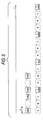
- Fig. 3 is a diagram showing an image forming pattern in the case that images corresponding to four pages in total are formed on the faces and backs of two papers having the A4 size.
- the case of a monochrome image process is illustrated in an upper stage and the case of a color image process is illustrated in a lower stage, in which an axis of abscissa indicates a time (t).
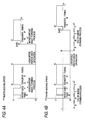
- Fig. 4A is a diagram mainly showing the delivery speed of the paper in a monochrome image process
- Fig. 4B is a diagram mainly showing the delivery speed of the paper in a color image process, in which an axis of ordinate indicates a speed (V) and an axis of abscissa indicates a time (t).
- an image of a second page ((2 back) in the drawing) for either side (a back) of a first paper is first formed on the intermediate transfer belt 51, the same image is transferred and fixed to either side of the first paper (the second page), the first paper is returned, and then, an image of a first page ((1 face) in the drawing) for the other side (a face) of the first paper is formed, the same image is transferred and fixed to the other side of the first paper (the first page), and the paper is discharged to the paper discharge tray 15.
- an image of a fourth page ((4 back) in the drawing) for either side (a back) of a second paper is formed on the intermediate transfer belt 51, the same image is transferred and fixed to either side of the second paper (the fourth page), the second paper is returned, and then, an image of a third page ((3 face) in the drawing) for the other side (a face) of the second paper is formed, the same image is transferred and fixed to the other side of the second paper (the third page), and the paper is discharged to the paper discharge tray 15.
- a black image (B), a magenta image (M), a cyan image (C), and a yellow image (Y) for either side (a back) of a first paper are first superposed on the intermediate transfer belt 51 to form an image of a second page ((Y2 back) in the drawing), and at the same time, to transfer and fix a color image obtained by superposing the four colors to either side of the first paper (the second page), and the image (B, M, C, Y) of a first page for the other side (a face) of the first paper is formed while the first paper is returned, and the image ((Y1 face) in the drawing) is transferred and fixed to the other side of the first paper (the first page) and the paper is discharged to the paper discharge tray 15.
- an image (B, M, C, Y) of a fourth page for either side (a back) of a second paper is formed on the intermediate transfer belt 51, the image ((Y4 back) in the drawing) is transferred and fixed to either side (the fourth page) of the second paper, and the image (B, M, C, Y) of a third page for the other side (a face) of the second paper is formed while the second paper is returned, and the image ((Y3 face) in the drawing) is transferred and fixed to the other surface of the second paper (a third page) and the paper is discharged to the paper discharge tray 15.
- Figs. 4A and 4B show a relationship between the image forming pattern and a paper delivery speed.
- a feeding of a paper is started at a speed v1 at a time t0, and the delivery of the paper is once stopped when the tip of the paper reaches the pair of gate rollers 10g (t1), and at the same time, the image of the second page for the either side (the back) of the first paper is started to be formed on the intermediate transfer belt 51.
- the delivery of the paper is started at the speed v1 in a predetermined timing t2 and a transfer to either side of the paper (the second page) is started at a time t3, and a fixation is started at a time t4.
- the pair of switchback rollers 93 are reversed at (or immediately before) a time t5 that the rear end of the paper reaches the nip portion of the pair of switchback rollers 93, the paper is returned at a higher speed v2 than the speed v1, and the delivery of the paper is once stopped, and at the same time, the image of the first page for the other side (the face) of the paper is started to be formed on the intermediate transfer belt 51 at a time (t1') that the rear end of the paper (a tip in a return direction) reaches the pair of gate rollers 10g.
- the delivery of the paper is started at the speed v1 in a predetermined timing t2', a transfer to the face (the first page) of the paper is started at a time t3' and a fixation is started at a time t4', and the paper is discharged to the paper discharge tray 15.
- an image (B, M, C, Y) of a second page for either side (a back) of a first paper is started to be formed on the intermediate transfer belt 51 at a time -t. Then, the paper is started to be fed at a speed v1 at a time t0, and the delivery of the paper is once stopped at a time (t1) that the tip of the paper reaches the pair of gate rollers 10g, the delivery of the paper is started at the speed v1 in a predetermined timing t2, a transfer to either side (the second page) of the paper is started at a time t3, and a fixation is started at a time t4.
- the pair of switchback rollers 93 are reversed at (or immediately before) a time t5 that the rear end of the paper reaches the nip portion of the pair of switchback rollers 93, the paper is returned at a low speed v2 which is equal to or less than the speed v1 (in the embodiment, v2 is equal to the delivery speed v1), and the image (B, M, C, Y) of a first page for the other side (the face) of the first paper is started to be formed on the intermediate transfer belt 51 in a predetermined timing t6.
- the delivery of the paper is once stopped at a time (t1') that the rear end of the paper to be returned (a tip in a return direction) reaches the pair of gate rollers 10g, the delivery of the paper is started at the speed v1 in a predetermined timing t2', a transfer to the surface (the first page) of the paper is started at a time t3', a fixation is started at a time t4', and the paper is discharged to the paper discharge tray 15.
- the return speed v2 of the paper is equal to a speed at which the tip in the delivery direction of the paper reaches the transfer portion at the time t3' that the color image is transferred to the other surface of the paper in the transfer portion (secondary transfer portion) T2.
- the process is controlled by a control portion (not shown) which is provided in the image forming apparatus body.
- the image forming apparatus described above includes:
- the paper is returned at a low speed v2 which is equal to or lower than the delivery speed v1 in the transfer. Therefore, a noise made by returning the paper can be reduced.
- an image forming apparatus having such a structure as to form an image having one color on the intermediate transfer member 51 per rotation of the intermediate transfer member 51 in the formation of a color image and to superpose images having a plurality of colors on the intermediate transfer member 51 by a plurality of rotations of the intermediate transfer member 51, thereby forming color images on the intermediate transfer member 51, and to transfer the color images to the paper in a lump in the transfer portion T2, even if the paper is returned at a high speed, the image cannot be transferred before the superposition of the color image is completed (see Figs. 4A and 4B). For this reason, the return at an unnecessarily high speed is useless, resulting in an increase in a noise.
- the image forming apparatus when a color image is formed in the image forming portion for the other surface of the paper, the paper is returned at a low speed which is equal to or lower than the delivery speed in the transfer. Consequently, it is possible to reduce a noise which is made by the return of the paper.
- the return speed v1 of the paper at this time is set to be equal to a speed at which the tip in the delivery direction of the paper reaches the transfer portion T2 in the transfer in which the color image is transferred to the other surface of the paper in the transfer portion T2. Therefore, it is possible to prevent the number of sheets on which the image is formed per unit time from being reduced in the formation of a color image on both surfaces of the paper.
- the paper is returned at a higher speed v2 than the delivery speed in the transfer. Consequently, it is possible to increase the number of the sheets on which the monochrome image is formed per unit time.
Landscapes
- Physics & Mathematics (AREA)
- General Physics & Mathematics (AREA)
- Chemical & Material Sciences (AREA)
- Inorganic Chemistry (AREA)
- Color Electrophotography (AREA)
- Control Or Security For Electrophotography (AREA)
- Electrostatic Charge, Transfer And Separation In Electrography (AREA)
- Counters In Electrophotography And Two-Sided Copying (AREA)
- Paper Feeding For Electrophotography (AREA)
- Photographic Developing Apparatuses (AREA)
- Printers Or Recording Devices Using Electromagnetic And Radiation Means (AREA)
- Forging (AREA)
- Printers Characterized By Their Purpose (AREA)
Applications Claiming Priority (1)
| Application Number | Priority Date | Filing Date | Title |
|---|---|---|---|
| JP2004283949A JP2006098659A (ja) | 2004-09-29 | 2004-09-29 | 画像形成装置 |
Publications (3)
| Publication Number | Publication Date |
|---|---|
| EP1643316A2 true EP1643316A2 (de) | 2006-04-05 |
| EP1643316A3 EP1643316A3 (de) | 2006-08-02 |
| EP1643316B1 EP1643316B1 (de) | 2008-03-26 |
Family
ID=35115993
Family Applications (1)
| Application Number | Title | Priority Date | Filing Date |
|---|---|---|---|
| EP05021198A Not-in-force EP1643316B1 (de) | 2004-09-29 | 2005-09-28 | Bilderzeugungsgerät |
Country Status (5)
| Country | Link |
|---|---|
| US (1) | US7469123B2 (de) |
| EP (1) | EP1643316B1 (de) |
| JP (1) | JP2006098659A (de) |
| AT (1) | ATE390650T1 (de) |
| DE (1) | DE602005005595T2 (de) |
Cited By (1)
| Publication number | Priority date | Publication date | Assignee | Title |
|---|---|---|---|---|
| EP1715670A1 (de) * | 2005-04-22 | 2006-10-25 | Seiko Epson Corporation | Papiertransportgeschwindigkeitssteuerung in Duplex-Farbbilderzeugungsvorrichtung |
Families Citing this family (2)
| Publication number | Priority date | Publication date | Assignee | Title |
|---|---|---|---|---|
| JP5538875B2 (ja) * | 2009-12-25 | 2014-07-02 | キヤノン株式会社 | 画像形成装置 |
| EP4116633A4 (de) * | 2020-03-05 | 2023-12-06 | Hitachi-Johnson Controls Air Conditioning, Inc. | Klimaanlage |
Family Cites Families (5)
| Publication number | Priority date | Publication date | Assignee | Title |
|---|---|---|---|---|
| JPS58178373A (ja) * | 1982-04-13 | 1983-10-19 | Minolta Camera Co Ltd | 両面複写機 |
| JPH096206A (ja) * | 1995-06-18 | 1997-01-10 | Canon Inc | 画像形成装置 |
| JP2000128442A (ja) * | 1998-10-27 | 2000-05-09 | Canon Inc | 画像形成装置 |
| US6450711B1 (en) | 2000-12-05 | 2002-09-17 | Xerox Corporation | High speed printer with dual alternate sheet inverters |
| JP2003050528A (ja) * | 2001-08-06 | 2003-02-21 | Sharp Corp | 画像形成装置 |
-
2004
- 2004-09-29 JP JP2004283949A patent/JP2006098659A/ja active Pending
-
2005
- 2005-09-28 AT AT05021198T patent/ATE390650T1/de not_active IP Right Cessation
- 2005-09-28 US US11/239,670 patent/US7469123B2/en not_active Expired - Fee Related
- 2005-09-28 EP EP05021198A patent/EP1643316B1/de not_active Not-in-force
- 2005-09-28 DE DE602005005595T patent/DE602005005595T2/de active Active
Cited By (1)
| Publication number | Priority date | Publication date | Assignee | Title |
|---|---|---|---|---|
| EP1715670A1 (de) * | 2005-04-22 | 2006-10-25 | Seiko Epson Corporation | Papiertransportgeschwindigkeitssteuerung in Duplex-Farbbilderzeugungsvorrichtung |
Also Published As
| Publication number | Publication date |
|---|---|
| ATE390650T1 (de) | 2008-04-15 |
| US20060067761A1 (en) | 2006-03-30 |
| JP2006098659A (ja) | 2006-04-13 |
| US7469123B2 (en) | 2008-12-23 |
| DE602005005595D1 (de) | 2008-05-08 |
| EP1643316A3 (de) | 2006-08-02 |
| DE602005005595T2 (de) | 2009-04-30 |
| EP1643316B1 (de) | 2008-03-26 |
Similar Documents
| Publication | Publication Date | Title |
|---|---|---|
| JPH11249346A (ja) | 連続紙の記録装置 | |
| JP2010061060A (ja) | 画像形成装置 | |
| JP2004099293A (ja) | 画像形成装置 | |
| JPH11170637A (ja) | 印刷媒体を選択可能な印刷システム | |
| US7469123B2 (en) | Image forming apparatus | |
| JP2806956B2 (ja) | 多色像形成装置の運転方法 | |
| US7310487B2 (en) | Image forming apparatus with controlled timing of contact of cleaning blade against intermediate transfer member | |
| JPH10333525A (ja) | 画像形成装置 | |
| JP2004020616A (ja) | 画像形成装置 | |
| JP4343499B2 (ja) | 多色画像形成装置および多色画像形成方法 | |
| US9989918B2 (en) | Image forming apparatus having defined arrangement of heat discharge duct | |
| JP2000321953A (ja) | 画像形成装置 | |
| EP1640299A1 (de) | Bilderzeugungsgerät | |
| JPH08225219A (ja) | 画像形成装置 | |
| JP2000351512A (ja) | 排紙装置 | |
| JP4572178B2 (ja) | 画像形成装置 | |
| US20060280536A1 (en) | Sheet conveyance apparatus | |
| US9725258B2 (en) | Image forming device | |
| JP5943235B2 (ja) | 画像形成装置 | |
| JP2001337573A (ja) | 画像形成装置 | |
| JP2006168956A (ja) | 画像形成装置における給紙装置 | |
| JP2006030402A (ja) | 画像形成方法及び画像形成装置 | |
| JPH1124330A (ja) | 両面画像形成装置 | |
| JPH09269616A (ja) | 両面画像形成方法及びその装置 | |
| JP2006133350A (ja) | 画像形成装置 |
Legal Events
| Date | Code | Title | Description |
|---|---|---|---|
| PUAI | Public reference made under article 153(3) epc to a published international application that has entered the european phase |
Free format text: ORIGINAL CODE: 0009012 |
|
| AK | Designated contracting states |
Kind code of ref document: A2 Designated state(s): AT BE BG CH CY CZ DE DK EE ES FI FR GB GR HU IE IS IT LI LT LU LV MC NL PL PT RO SE SI SK TR |
|
| AX | Request for extension of the european patent |
Extension state: AL BA HR MK YU |
|
| PUAL | Search report despatched |
Free format text: ORIGINAL CODE: 0009013 |
|
| AK | Designated contracting states |
Kind code of ref document: A3 Designated state(s): AT BE BG CH CY CZ DE DK EE ES FI FR GB GR HU IE IS IT LI LT LU LV MC NL PL PT RO SE SI SK TR |
|
| AX | Request for extension of the european patent |
Extension state: AL BA HR MK YU |
|
| 17P | Request for examination filed |
Effective date: 20070202 |
|
| AKX | Designation fees paid |
Designated state(s): AT BE BG CH CY CZ DE DK EE ES FI FR GB GR HU IE IS IT LI LT LU LV MC NL PL PT RO SE SI SK TR |
|
| RIC1 | Information provided on ipc code assigned before grant |
Ipc: G03G 15/23 20060101ALI20070814BHEP Ipc: G03G 15/01 20060101AFI20070814BHEP Ipc: G03G 15/00 20060101ALI20070814BHEP |
|
| GRAP | Despatch of communication of intention to grant a patent |
Free format text: ORIGINAL CODE: EPIDOSNIGR1 |
|
| GRAS | Grant fee paid |
Free format text: ORIGINAL CODE: EPIDOSNIGR3 |
|
| GRAA | (expected) grant |
Free format text: ORIGINAL CODE: 0009210 |
|
| AK | Designated contracting states |
Kind code of ref document: B1 Designated state(s): AT BE BG CH CY CZ DE DK EE ES FI FR GB GR HU IE IS IT LI LT LU LV MC NL PL PT RO SE SI SK TR |
|
| REG | Reference to a national code |
Ref country code: GB Ref legal event code: FG4D |
|
| REG | Reference to a national code |
Ref country code: CH Ref legal event code: EP Ref country code: IE Ref legal event code: FG4D |
|
| REF | Corresponds to: |
Ref document number: 602005005595 Country of ref document: DE Date of ref document: 20080508 Kind code of ref document: P |
|
| PG25 | Lapsed in a contracting state [announced via postgrant information from national office to epo] |
Ref country code: FI Free format text: LAPSE BECAUSE OF FAILURE TO SUBMIT A TRANSLATION OF THE DESCRIPTION OR TO PAY THE FEE WITHIN THE PRESCRIBED TIME-LIMIT Effective date: 20080326 |
|
| PG25 | Lapsed in a contracting state [announced via postgrant information from national office to epo] |
Ref country code: AT Free format text: LAPSE BECAUSE OF FAILURE TO SUBMIT A TRANSLATION OF THE DESCRIPTION OR TO PAY THE FEE WITHIN THE PRESCRIBED TIME-LIMIT Effective date: 20080326 |
|
| NLV1 | Nl: lapsed or annulled due to failure to fulfill the requirements of art. 29p and 29m of the patents act | ||
| PG25 | Lapsed in a contracting state [announced via postgrant information from national office to epo] |
Ref country code: SI Free format text: LAPSE BECAUSE OF FAILURE TO SUBMIT A TRANSLATION OF THE DESCRIPTION OR TO PAY THE FEE WITHIN THE PRESCRIBED TIME-LIMIT Effective date: 20080326 Ref country code: BE Free format text: LAPSE BECAUSE OF FAILURE TO SUBMIT A TRANSLATION OF THE DESCRIPTION OR TO PAY THE FEE WITHIN THE PRESCRIBED TIME-LIMIT Effective date: 20080326 Ref country code: PL Free format text: LAPSE BECAUSE OF FAILURE TO SUBMIT A TRANSLATION OF THE DESCRIPTION OR TO PAY THE FEE WITHIN THE PRESCRIBED TIME-LIMIT Effective date: 20080326 Ref country code: LV Free format text: LAPSE BECAUSE OF FAILURE TO SUBMIT A TRANSLATION OF THE DESCRIPTION OR TO PAY THE FEE WITHIN THE PRESCRIBED TIME-LIMIT Effective date: 20080326 |
|
| PG25 | Lapsed in a contracting state [announced via postgrant information from national office to epo] |
Ref country code: CZ Free format text: LAPSE BECAUSE OF FAILURE TO SUBMIT A TRANSLATION OF THE DESCRIPTION OR TO PAY THE FEE WITHIN THE PRESCRIBED TIME-LIMIT Effective date: 20080326 Ref country code: SK Free format text: LAPSE BECAUSE OF FAILURE TO SUBMIT A TRANSLATION OF THE DESCRIPTION OR TO PAY THE FEE WITHIN THE PRESCRIBED TIME-LIMIT Effective date: 20080326 Ref country code: ES Free format text: LAPSE BECAUSE OF FAILURE TO SUBMIT A TRANSLATION OF THE DESCRIPTION OR TO PAY THE FEE WITHIN THE PRESCRIBED TIME-LIMIT Effective date: 20080707 Ref country code: PT Free format text: LAPSE BECAUSE OF FAILURE TO SUBMIT A TRANSLATION OF THE DESCRIPTION OR TO PAY THE FEE WITHIN THE PRESCRIBED TIME-LIMIT Effective date: 20080901 Ref country code: SE Free format text: LAPSE BECAUSE OF FAILURE TO SUBMIT A TRANSLATION OF THE DESCRIPTION OR TO PAY THE FEE WITHIN THE PRESCRIBED TIME-LIMIT Effective date: 20080626 |
|
| PG25 | Lapsed in a contracting state [announced via postgrant information from national office to epo] |
Ref country code: NL Free format text: LAPSE BECAUSE OF FAILURE TO SUBMIT A TRANSLATION OF THE DESCRIPTION OR TO PAY THE FEE WITHIN THE PRESCRIBED TIME-LIMIT Effective date: 20080326 Ref country code: RO Free format text: LAPSE BECAUSE OF FAILURE TO SUBMIT A TRANSLATION OF THE DESCRIPTION OR TO PAY THE FEE WITHIN THE PRESCRIBED TIME-LIMIT Effective date: 20080326 |
|
| PG25 | Lapsed in a contracting state [announced via postgrant information from national office to epo] |
Ref country code: IS Free format text: LAPSE BECAUSE OF FAILURE TO SUBMIT A TRANSLATION OF THE DESCRIPTION OR TO PAY THE FEE WITHIN THE PRESCRIBED TIME-LIMIT Effective date: 20080726 |
|
| ET | Fr: translation filed | ||
| PG25 | Lapsed in a contracting state [announced via postgrant information from national office to epo] |
Ref country code: LT Free format text: LAPSE BECAUSE OF FAILURE TO SUBMIT A TRANSLATION OF THE DESCRIPTION OR TO PAY THE FEE WITHIN THE PRESCRIBED TIME-LIMIT Effective date: 20080326 Ref country code: DK Free format text: LAPSE BECAUSE OF FAILURE TO SUBMIT A TRANSLATION OF THE DESCRIPTION OR TO PAY THE FEE WITHIN THE PRESCRIBED TIME-LIMIT Effective date: 20080326 |
|
| PLBE | No opposition filed within time limit |
Free format text: ORIGINAL CODE: 0009261 |
|
| STAA | Information on the status of an ep patent application or granted ep patent |
Free format text: STATUS: NO OPPOSITION FILED WITHIN TIME LIMIT |
|
| 26N | No opposition filed |
Effective date: 20081230 |
|
| PG25 | Lapsed in a contracting state [announced via postgrant information from national office to epo] |
Ref country code: BG Free format text: LAPSE BECAUSE OF FAILURE TO SUBMIT A TRANSLATION OF THE DESCRIPTION OR TO PAY THE FEE WITHIN THE PRESCRIBED TIME-LIMIT Effective date: 20080626 Ref country code: EE Free format text: LAPSE BECAUSE OF FAILURE TO SUBMIT A TRANSLATION OF THE DESCRIPTION OR TO PAY THE FEE WITHIN THE PRESCRIBED TIME-LIMIT Effective date: 20080326 Ref country code: MC Free format text: LAPSE BECAUSE OF NON-PAYMENT OF DUE FEES Effective date: 20080930 |
|
| PG25 | Lapsed in a contracting state [announced via postgrant information from national office to epo] |
Ref country code: IE Free format text: LAPSE BECAUSE OF NON-PAYMENT OF DUE FEES Effective date: 20080929 |
|
| PG25 | Lapsed in a contracting state [announced via postgrant information from national office to epo] |
Ref country code: IT Free format text: LAPSE BECAUSE OF FAILURE TO SUBMIT A TRANSLATION OF THE DESCRIPTION OR TO PAY THE FEE WITHIN THE PRESCRIBED TIME-LIMIT Effective date: 20080326 |
|
| PG25 | Lapsed in a contracting state [announced via postgrant information from national office to epo] |
Ref country code: CY Free format text: LAPSE BECAUSE OF FAILURE TO SUBMIT A TRANSLATION OF THE DESCRIPTION OR TO PAY THE FEE WITHIN THE PRESCRIBED TIME-LIMIT Effective date: 20080326 |
|
| REG | Reference to a national code |
Ref country code: CH Ref legal event code: PL |
|
| PG25 | Lapsed in a contracting state [announced via postgrant information from national office to epo] |
Ref country code: HU Free format text: LAPSE BECAUSE OF FAILURE TO SUBMIT A TRANSLATION OF THE DESCRIPTION OR TO PAY THE FEE WITHIN THE PRESCRIBED TIME-LIMIT Effective date: 20080927 Ref country code: LU Free format text: LAPSE BECAUSE OF NON-PAYMENT OF DUE FEES Effective date: 20080928 |
|
| PG25 | Lapsed in a contracting state [announced via postgrant information from national office to epo] |
Ref country code: TR Free format text: LAPSE BECAUSE OF FAILURE TO SUBMIT A TRANSLATION OF THE DESCRIPTION OR TO PAY THE FEE WITHIN THE PRESCRIBED TIME-LIMIT Effective date: 20080326 |
|
| PG25 | Lapsed in a contracting state [announced via postgrant information from national office to epo] |
Ref country code: CH Free format text: LAPSE BECAUSE OF NON-PAYMENT OF DUE FEES Effective date: 20090930 Ref country code: GR Free format text: LAPSE BECAUSE OF FAILURE TO SUBMIT A TRANSLATION OF THE DESCRIPTION OR TO PAY THE FEE WITHIN THE PRESCRIBED TIME-LIMIT Effective date: 20080627 Ref country code: LI Free format text: LAPSE BECAUSE OF NON-PAYMENT OF DUE FEES Effective date: 20090930 |
|
| REG | Reference to a national code |
Ref country code: FR Ref legal event code: PLFP Year of fee payment: 12 |
|
| REG | Reference to a national code |
Ref country code: FR Ref legal event code: PLFP Year of fee payment: 13 |
|
| REG | Reference to a national code |
Ref country code: FR Ref legal event code: PLFP Year of fee payment: 14 |
|
| PGFP | Annual fee paid to national office [announced via postgrant information from national office to epo] |
Ref country code: DE Payment date: 20190917 Year of fee payment: 15 Ref country code: FR Payment date: 20190815 Year of fee payment: 15 |
|
| PGFP | Annual fee paid to national office [announced via postgrant information from national office to epo] |
Ref country code: GB Payment date: 20190926 Year of fee payment: 15 |
|
| REG | Reference to a national code |
Ref country code: DE Ref legal event code: R119 Ref document number: 602005005595 Country of ref document: DE |
|
| GBPC | Gb: european patent ceased through non-payment of renewal fee |
Effective date: 20200928 |
|
| PG25 | Lapsed in a contracting state [announced via postgrant information from national office to epo] |
Ref country code: FR Free format text: LAPSE BECAUSE OF NON-PAYMENT OF DUE FEES Effective date: 20200930 Ref country code: DE Free format text: LAPSE BECAUSE OF NON-PAYMENT OF DUE FEES Effective date: 20210401 |
|
| PG25 | Lapsed in a contracting state [announced via postgrant information from national office to epo] |
Ref country code: GB Free format text: LAPSE BECAUSE OF NON-PAYMENT OF DUE FEES Effective date: 20200928 |