EP1647226B1 - Hermetisch abgeschlossener behälter und vakuum-testsubstanz-aufnahme-behälter - Google Patents
Hermetisch abgeschlossener behälter und vakuum-testsubstanz-aufnahme-behälter Download PDFInfo
- Publication number
- EP1647226B1 EP1647226B1 EP04747670A EP04747670A EP1647226B1 EP 1647226 B1 EP1647226 B1 EP 1647226B1 EP 04747670 A EP04747670 A EP 04747670A EP 04747670 A EP04747670 A EP 04747670A EP 1647226 B1 EP1647226 B1 EP 1647226B1
- Authority
- EP
- European Patent Office
- Prior art keywords
- container
- stopper
- blood
- sampling
- leg portion
- Prior art date
- Legal status (The legal status is an assumption and is not a legal conclusion. Google has not performed a legal analysis and makes no representation as to the accuracy of the status listed.)
- Expired - Lifetime
Links
Images






Classifications
-
- A—HUMAN NECESSITIES
- A61—MEDICAL OR VETERINARY SCIENCE; HYGIENE
- A61J—CONTAINERS SPECIALLY ADAPTED FOR MEDICAL OR PHARMACEUTICAL PURPOSES; DEVICES OR METHODS SPECIALLY ADAPTED FOR BRINGING PHARMACEUTICAL PRODUCTS INTO PARTICULAR PHYSICAL OR ADMINISTERING FORMS; DEVICES FOR ADMINISTERING FOOD OR MEDICINES ORALLY; BABY COMFORTERS; DEVICES FOR RECEIVING SPITTLE
- A61J1/00—Containers specially adapted for medical or pharmaceutical purposes
- A61J1/05—Containers specially adapted for medical or pharmaceutical purposes for collecting, storing or administering blood, plasma or medical fluids ; Infusion or perfusion containers
-
- B—PERFORMING OPERATIONS; TRANSPORTING
- B01—PHYSICAL OR CHEMICAL PROCESSES OR APPARATUS IN GENERAL
- B01L—CHEMICAL OR PHYSICAL LABORATORY APPARATUS FOR GENERAL USE
- B01L3/00—Containers or dishes for laboratory use, e.g. laboratory glassware; Droppers
- B01L3/50—Containers for the purpose of retaining a material to be analysed, e.g. test tubes
- B01L3/508—Rigid containers without fluid transport within
- B01L3/5082—Test tubes per se
- B01L3/50825—Closing or opening means, corks, bungs
-
- A—HUMAN NECESSITIES
- A61—MEDICAL OR VETERINARY SCIENCE; HYGIENE
- A61B—DIAGNOSIS; SURGERY; IDENTIFICATION
- A61B5/00—Measuring for diagnostic purposes; Identification of persons
- A61B5/15—Devices for taking samples of blood
- A61B5/150007—Details
- A61B5/150015—Source of blood
- A61B5/15003—Source of blood for venous or arterial blood
-
- A—HUMAN NECESSITIES
- A61—MEDICAL OR VETERINARY SCIENCE; HYGIENE
- A61B—DIAGNOSIS; SURGERY; IDENTIFICATION
- A61B5/00—Measuring for diagnostic purposes; Identification of persons
- A61B5/15—Devices for taking samples of blood
- A61B5/150007—Details
- A61B5/150206—Construction or design features not otherwise provided for; manufacturing or production; packages; sterilisation of piercing element, piercing device or sampling device
- A61B5/150274—Manufacture or production processes or steps for blood sampling devices
-
- A—HUMAN NECESSITIES
- A61—MEDICAL OR VETERINARY SCIENCE; HYGIENE
- A61B—DIAGNOSIS; SURGERY; IDENTIFICATION
- A61B5/00—Measuring for diagnostic purposes; Identification of persons
- A61B5/15—Devices for taking samples of blood
- A61B5/150007—Details
- A61B5/150351—Caps, stoppers or lids for sealing or closing a blood collection vessel or container, e.g. a test-tube or syringe barrel
-
- A—HUMAN NECESSITIES
- A61—MEDICAL OR VETERINARY SCIENCE; HYGIENE
- A61B—DIAGNOSIS; SURGERY; IDENTIFICATION
- A61B5/00—Measuring for diagnostic purposes; Identification of persons
- A61B5/15—Devices for taking samples of blood
- A61B5/150007—Details
- A61B5/150374—Details of piercing elements or protective means for preventing accidental injuries by such piercing elements
- A61B5/150381—Design of piercing elements
- A61B5/150389—Hollow piercing elements, e.g. canulas, needles, for piercing the skin
-
- A—HUMAN NECESSITIES
- A61—MEDICAL OR VETERINARY SCIENCE; HYGIENE
- A61B—DIAGNOSIS; SURGERY; IDENTIFICATION
- A61B5/00—Measuring for diagnostic purposes; Identification of persons
- A61B5/15—Devices for taking samples of blood
- A61B5/150007—Details
- A61B5/150374—Details of piercing elements or protective means for preventing accidental injuries by such piercing elements
- A61B5/150381—Design of piercing elements
- A61B5/150473—Double-ended needles, e.g. used with pre-evacuated sampling tubes
-
- A—HUMAN NECESSITIES
- A61—MEDICAL OR VETERINARY SCIENCE; HYGIENE
- A61B—DIAGNOSIS; SURGERY; IDENTIFICATION
- A61B5/00—Measuring for diagnostic purposes; Identification of persons
- A61B5/15—Devices for taking samples of blood
- A61B5/150007—Details
- A61B5/150374—Details of piercing elements or protective means for preventing accidental injuries by such piercing elements
- A61B5/150534—Design of protective means for piercing elements for preventing accidental needle sticks, e.g. shields, caps, protectors, axially extensible sleeves, pivotable protective sleeves
- A61B5/150572—Pierceable protectors, e.g. shields, caps, sleeves or films, e.g. for hygienic purposes
-
- A—HUMAN NECESSITIES
- A61—MEDICAL OR VETERINARY SCIENCE; HYGIENE
- A61B—DIAGNOSIS; SURGERY; IDENTIFICATION
- A61B5/00—Measuring for diagnostic purposes; Identification of persons
- A61B5/15—Devices for taking samples of blood
- A61B5/150007—Details
- A61B5/150732—Needle holders, for instance for holding the needle by the hub, used for example with double-ended needle and pre-evacuated tube
-
- A—HUMAN NECESSITIES
- A61—MEDICAL OR VETERINARY SCIENCE; HYGIENE
- A61J—CONTAINERS SPECIALLY ADAPTED FOR MEDICAL OR PHARMACEUTICAL PURPOSES; DEVICES OR METHODS SPECIALLY ADAPTED FOR BRINGING PHARMACEUTICAL PRODUCTS INTO PARTICULAR PHYSICAL OR ADMINISTERING FORMS; DEVICES FOR ADMINISTERING FOOD OR MEDICINES ORALLY; BABY COMFORTERS; DEVICES FOR RECEIVING SPITTLE
- A61J1/00—Containers specially adapted for medical or pharmaceutical purposes
-
- B—PERFORMING OPERATIONS; TRANSPORTING
- B01—PHYSICAL OR CHEMICAL PROCESSES OR APPARATUS IN GENERAL
- B01L—CHEMICAL OR PHYSICAL LABORATORY APPARATUS FOR GENERAL USE
- B01L2200/00—Solutions for specific problems relating to chemical or physical laboratory apparatus
- B01L2200/06—Fluid handling related problems
- B01L2200/0689—Sealing
-
- B—PERFORMING OPERATIONS; TRANSPORTING
- B01—PHYSICAL OR CHEMICAL PROCESSES OR APPARATUS IN GENERAL
- B01L—CHEMICAL OR PHYSICAL LABORATORY APPARATUS FOR GENERAL USE
- B01L2300/00—Additional constructional details
- B01L2300/04—Closures and closing means
- B01L2300/041—Connecting closures to device or container
- B01L2300/042—Caps; Plugs
Definitions
- the present invention relates to a sealed container which comprises a container comprising a thermoplastic resin and a stopper which is hardly slackening even when used in combination with the container, and a vacuum specimen-sampling container comprising the sealed container.
- vacuum specimen-sampling containers wherein sealed containers, the inside being under a reduced atmospheric pressure state
- vacuum specimen-sampling containers for example, vacuum blood-sampling tubes are most generally used.
- An example of such vacuum blood-sampling tubes is disclosed in Patent Document 1, for instance.
- FIGs. 21(a) to 21(c) One example of the vacuum blood-sampling system disclosed in Patent Document 1 is shown in Figs. 21(a) to 21(c) .
- This vacuum blood-sampling system comprises a vacuum blood-sampling container 80 shown in Fig. 21(a) , a vacuum blood-sampling holder 83 shown in Fig. 21(b) and a vacuum blood-sampling needle 85 shown in Fig. 21(c) .
- the vacuum blood-sampling container 80 comprises a blood-sampling tube 82 with an opening at an end and a stopper 81 which seals the opening of the blood-sampling tube 82.
- the stopper 81 is made of an elastic material having a needle-hole sealing property and a gas barrier property.
- the vacuum blood-sampling holder 83 is designed so that the vacuum blood-sampling container 80 is inserted therein from the opening at an end.
- a blood-sampling needle holding hole 84 is formed at the other end of the vacuum blood-sampling holder 83, an internal thread is formed in the blood-sampling needle holding hole 84.
- the vacuum blood-sampling needle 85 has needle tips 87 and 88 at the both ends.
- a hub 86 on which an external thread portion is formed is formed on the needle tip 87 side. The hub 86 is designed to be screwed into the blood-sampling needle holding hole 84 of the vacuum blood-sampling holder 83 to be secured therein.
- Fig. 23 is a schematic perspective view to explain a method of sampling blood by using the vacuum blood-sampling system disclosed in Patent Document 1. Referring to Fig. 21 and Fig. 23 , the blood-sampling step is explained.
- the vacuum blood-sampling needle 85 is threadedly engaged with the blood-sampling needle holding hole 84 of the vacuum blood-sampling holder 83.
- the vacuum blood-sampling container 80 is inserted into the holder 83, and pushed in such a degree that the needle tip 87 of the vacuum blood-sampling needle 85 does not penetrate the stopper 81, and the needle tip 87 is once sealed. This makes it possible to prevent blood leaking from the needle tip 87, in insertion of the needle tip 88 into a blood vessel. As shown in Fig.
- the blood-sampling operator inserts the tip of the needle 88 on the blood-vessel piercing side into a blood vessel.
- the needle tip 87 penetrates the stopper 81, and blood flows into the blood-sampling container 80 in accordance with a pressure difference between the blood-sampling container side and the blood vessel side.
- the blood-sampling needle 85 is called as a so-called single blood-sampling needle, which is used when the blood sampling is carried out into a single vacuum blood-sampling container.
- this single blood-sampling needle cannot be used.
- the needle tip 88 since, in exchanging blood-sampling containers, the needle tip 88 needs to be kept inserted into the blood vessel, blood is leaked from the needle tip 87 in the case of using the single blood-sampling needle.
- a multiple blood-sampling needle 89 having a structure shown in Fig.
- a material used for the blood-sampling tube 82 shown in Fig. 21(a) conventionally, glass has been used, however, in recent years, in place of the blood-sampling tube made of glass, a plastic blood-sampling tube made of a thermoplastic resin having a superior gas-barrier property, such as polyethylene terephthalate, has been used in many cases.
- a plastic blood-sampling tube made of a thermoplastic resin having a superior gas-barrier property such as polyethylene terephthalate
- cross-linking isobutylene-isoprene rubber cross-linking IIR, cross-linking butyl rubber
- the cross-linking rubber requires a long period of time for a curing reaction step and post-steps, such as water-washing and removing steps of a curing reaction agent and elusive substances derived from side products, etc. of the curing reaction, resulting in degradation in the productivity.
- stoppers prepared by using a thermoplastic resin and a thermoplastic elastomer which can be injection-molded, is proposed, for example, in Patent Documents 2 to 7.
- the blood-sampling container is again sealed with the stopper 81 for re-inspection, and stored in a cold state or in a frozen state.
- Patent Document 8 discloses a stopper for a bottle having a fit-in structure in which a ring-shaped rib, which protrudes on an internal wall surface or on an external wall surface in the vicinity of an open end of a blood-sampling tube made of glass or plastics, is formed and a ring-shaped groove which is engaged with the ring-shaped rib is formed in a rubber stopper.
- Patent Document 10 discloses an opening and closing device for a cylinder-shaped case in which a screw cap and a rubber stopper are combined with each other.
- the blood-sampling tube made of glass may adopt these structures
- the blood-sampling tube made of plastics has a difficulty in adopting these structures because the dimension of the protrusion of the ring-shaped rib to be prepared is limited to only a small one which does not impair the releasing property from the metal mold, unless a complex sliding mechanism is incorporated into a molding metal mold, and it becomes difficult to obtain a clear fitting-in effect.
- the screw cap structure requires frequent attaching and detaching operations to consume much labor in repeating the opening and closing operations of a number of blood-sampling tubes.
- thermoplastic resin and the thermoplastic elastomer are extremely greater in compression permanent strain in comparison with thermosetting elastomers. For this reason, as time elapses after such a stopper was attached to a blood-sampling tube, in particular, when left for a long time under high temperatures in summer, the fitting force between the stopper and the blood-sampling tube is almost lost in a very short time of days.
- WO 01/47636 A2 discloses: a sealed container, which comprises a container with an end being closed and the other end being open and a stopper being detachable and capable of sealing the open end of the container, the stopper having a head portion capable of being grasped, a leg portion A being extended downward from the head portion, being along an internal wall surface of the open end of the container, and being capable of exerting a fitting force to the internal wall surface, and a leg portion being extended downward from the head portion, being along an external wall surface of the open end of the container, and being capable of exerting a fitting force to the external wall surface
- US Patent 5,033,476 shows a blood collecting tube with a tubular body that is opened at one end and is closed at the other end and a sealing member which can be pierced by a hollow needle and is bonded to peripheral edge of the opening of the tubular body to seal the opening in which the internal pressure of the tubular body is suitable reduced in accordance with the amount of blood to be collected, and the aforesaid sealing member is made up of: a gas barrier member having high air-tightness for substantially maintaining the degree of reduction in the internal pressure of the blood colleting tube during a period up to blood collection; and a sealing element capable of stopping up the needle hole which might remain after extraction of the hollow needle which has been stuck into the sealing member for blood collection.
- a sealed container which comprises a container comprising a thermoplastic resin and a stopper which is hardly slackening even when used in combination with the container, and a vacuum specimen-sampling container comprising the sealed container.
- the present invention is defined in claim 1 with a sealed container, which comprises a container with an end being closed and the other end being open, comprising a thermoplastic resin, and a stopper being detachable and capable of sealing the open end of the container, the stopper having a head portion capable of being grasped, a leg portion A being extended downward from the head portion, being along an internal wall surface of the open end of the container, and being capable of exerting a fitting force to the internal wall surface, and a leg portion B being extended downward from the head portion, being along an external wall surface of the open end of the container, and being capable of exerting a fitting force to the external wall surface, and a deflection temperature under load of at least a portion of the leg portion B of the stopper contacting with the container under a load of 0.45 MPa or 0.46 MPa is higher than a deflection temperature under load of at least a portion of the container contacting with the leg portion A of the stopper under a load of 0.45 MPa or 0.46 MPa wherein a
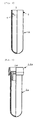
- Fig. 1 is a semi-sectional view which shows a partially cut-out portion of a sealed container in accordance with one embodiment of the present invention.
- a stopper 10 is fitted to a container 2.
- Fig. 2 is a semi-sectional view which shows a partially cut-out portion of the stopper 10
- Fig. 3 is a semi-sectional view which shows a partially cut-out portion of the container 2.
- the stopper 10 has a head portion 20 capable of being grasped, a partition wall portion 50 which crosses the open end 3 of the container 2, a leg portion A30 which is extended downward from the head portion 20, and is along the internal wall surface 4 of the open end 3 of the container 2, and being capable of exerting a fitting force to the internal wall surface 4, and a leg portion B40 which is extended downward from the head portion 20, and is along the external wall surface 5 of the open end 3 of the container 2, and being capable of exerting a fitting force to the external wall surface 5 in the vicinity 41 of the open end.
- being capable of exerting a fitting force means that attaching and detaching of the stopper are carried out against a sliding resistance.
- the external diameter of the leg portion A30 of the stopper 10 receives a narrowing force, and the internal diameter of the container 2 is subjected to an expanding force.
- the internal diameter of the container 2 is expanding, an increased fitting force by the leg portion B40 of the stopper 10 is applied to the container 2.
- At least a portion of the leg portion B40 of the stopper 10 contacting with the container 2 and at least a portion of the container 2 contacting with the leg portion A30 of the stopper 10 may have a deflection temperature under load of 60°C or more under a load of 0.45 MPa or 0.46 MPa.
- the deflection temperature under load at these portions is less than 60°C, the creep speed of the material of the stopper 10 becomes very high when the sealed container 1 is stored for a long period of time under high temperatures in summer, the fitting force to the container 2 is reduced and lost in a short period of time, and the stopper is easily slackened. It may be 70°C or more.
- a deflection temperature under load at least at a portion of the leg portion B40 of contacting with the container 2 under a load of 0.45 MPa or 0.46 MPa is higher than a deflection temperature under load at least at a portion of the container 2 contacting with the leg portion A30 of the stopper 10 under a load of 0.45 MPa or 0.46 MPa.
- the internal diameter of the open end of the container 2 is prevented from being expanded due to a fitting force exerted from the outside of the container 2 by the leg portion B40 of the stopper, thereby making it possible to prevent the stopper 10 from coming off due to slackening.
- the degree of deformation under load can be evaluated by any one of the deflection temperature under load, the vicut softening point and the tensile creep extension.
- the deflection temperature under load (also referred to as thermal deformation temperature) is measured by a method in accordance with, for example, ISO75, ISO1873, ASTM D648, JIS K 6921, JIS K 7191 and the like.
- the vicut softening point is measured by a method in accordance with, for example, ISO 306, ASTM D648, ASTM D1525, JIS K 7206 and the like.
- the tensile creep extension is measured by a method in accordance with JIS K 7115 and the like.
- the deflection temperature under load or the vicut softening point As an index, as the temperature at which a fixed amount of deformation or a fixed amount of intrusion has been reached under a fixed load becomes lower, it is determined that the heat resistance is lower.
- the tensile creep extension As the change in the length of a test piece under fixed temperature, load and load-applying time becomes greater, it is determined that the heat resistance is lower.
- the test method which best reflects the slackening phenomenon in fitting of the stopper is the tensile creep extension method, however, in the present invention, it is determined by the deflection temperature under load, since the measurement is easily carried out.
- the distance of the leg portion B40 of the stopper 10 contacting with the external wall surface 5 of the container 2 is shorter than the distance of the leg portion A30 contacting with the internal wall surface 4 of the container 2 in the longitudinal direction of the container 2.
- the distance of the leg portion B40 of the stopper 10 contacting with the external wall surface of the container 2 is shorter than the distance of the leg portion A30 contacting with the internal wall surface of the container 2 in the longitudinal direction of the container main body 2
- the container internal diameter at a portion on the bottom side from the open end which is not subjected to a fitting force of the leg portion B40 causes a creeping due to a fitting force exerted from the inside of the leg portion A30, thereby it is expanding.
- the container is deformed into a shape with a narrowed opening so that the coming off of the stopper 10 due to slackening is prevented more effectively. Therefore, even when the sealed container 1 is laterally laid down or kept upside down after the blood sampling, it becomes possible to prevent leak of the blood, or when, after a portion of the specimen is taken with the stopper being detached, the stopper 10 is again attached, it becomes possible to prevent the stopper 10 from gradually rising up and consequently coming off, and thus, the container is kept free from problems that might impair functions as a sealed container.
- the leg portion B40 of the stopper 10 in the case when the entire leg portion B40 of the stopper 10 is in contact with the external wall surface 5 of the container 2, after repeatedly attaching and detaching the stopper 10 to and from the container, the blood inside the container sinks into a gap between the leg portion B40 and the external wall surface 5 of the container 2, and tends to contaminate the fingers of the operator. Therefore, the leg portion B40 preferably has an end portion which is formed along the external wall surface 5 of the container 2, without being in contact with the external wall surface 5 of the container 2.
- the materials constituting the container 2 and the stopper 10 are properly selected so as to satisfy the deflection temperature under load.
- the combination of materials constituting the container 2 and the stopper 10 is properly selected so that the deflection temperature under load of the container 2 and the stopper 10 satisfy the above-mentioned relationship.
- the container 2 comprises a thermoplastic resin.
- the thermoplastic resin forming the container 2 is not particularly limited, and includes chain or cyclic olefin-based resins, styrene-based resins, acrylic-based resins, acrylonitrile-based resins, acrylonitrile-styrene-based resins, acrylonitrile-styrene-butadiene-based resins, ester-based resins, amide-based resins and modified cellulose-based resins.
- the material used for forming the stopper 10 is not particularly limited, for example, in addition to the thermoplastic resins exemplified as the materials for the above-mentioned container, and includes thermoplastic resins, such as phenol-based resins, unsaturated ester-based resins, urea-based resins and melamine-based resins; metals such as aluminum and stainless; ceramics and the like.
- the method of manufacturing the stopper 10 is not particularly limited, for example, and a cutting may be used, and a method in which the head portion 20 and the leg portion B40 are integrally molded by using an extrusion compression molding method, an injection molding method and the like and to this, inserting the leg portion A30 which is molded in a separated manner may also be used.
- the head portion 20, the leg portion B40 and the leg portion A30 may of course be integrally molded.
- the method of manufacturing the container 2 is not particularly limited, and a conventionally known injection molding method may be used. By fitting the stopper 10 to the open portion of the container 2 thus formed, a sealed container 1 can be manufactured.
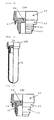
- Fig. 4 is a semi-sectional view which shows a partially cutout portion of a sealed container 1a derived from the embodiment shown in Fig. 1 .
- a stopper 10a is fitted to a container 2a.
- Fig. 5 is a semi-sectional view which shows a partially cutout portion of a stopper 10a
- Fig. 6 is a semi-sectional view which shows a partially cutout portion of a container 2a of Fig. 6 .
- the leg portion B40 which is extended downward from the head portion 20 of the stopper 10a, and is along the external wall surface 5 of the open end of the container 2a, and a portion 41 near the open end can be fitted to the external wall surface 5, since a ring-shaped rib 5a which protrudes outward is formed at the open end 3 of the container 2a.
- the other structures of the container and the stopper are the same as those of the embodiment shown in Fig. 1 .
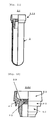
- Fig. 7 is a semi-sectional view which shows a partially cutout portion of a sealed container 1b of another preferred embodiment of the sealed container of the present invention.
- the stopper 10b is fitted to the container 2.
- Fig. 8 is a semi-sectional view which shows a partially cutout portion of a stopper 10b.
- a position of a fitting force exerted between the leg portion A30 of the stopper 10b and the internal wall surface 4 of the container 2 being greatest and a position of a fitting force exerted between the leg portion B40 of the stopper 10b and the external wall surface 5 of the container 2 being greatest are located at different positions in the longitudinal direction of the container 2.
- the internal diameter of the container 2 and the external diameter of the leg portion A30 are determined so that the greatest fitting force between the leg portion A30 which is extended downward from the head portion 20 of the stopper 10b and the internal wall surface 4 of the container 2 is exerted on an internal recessed side of the container 2 from the fitting portion 41 between the leg portion B40 and the external wall surface 5 of the container 2, that is, on the sealed end side, and a ring-shaped rib 31, which protrudes toward the internal wall surface 4 of the container 2, is formed on the leg portion A30.
- Such a ring-shaped rib 31 needs not to be formed on the leg portion A30 of the stopper 10b in a limited manner, and may be formed at the corresponding position of the internal wall surface 4 of the container 2 in a manner that it protrudes toward the leg portion A30. Moreover, the height and the number of the ring-shaped ribs 31 are not particularly limited, as long as no troubles are caused in forming the stopper through an injection molding method.
- the container 2 is easily deformed into a shape with a narrowed opening, and therefore, even when the sealed container 1b is stored for a long period of time under high temperatures, it becomes possible to prevent leak of the blood after the sampling, and also to prevent the stopper 10 from rising up from the sealed container 1b to impair the functions as a sealed container.
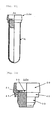
- Fig. 9 is a semi-sectional view which shows a partially cutout portion of a sealed container 1c of another preferred embodiment of the sealed container of the present invention.
- a stopper 10c is fitted to the container 2.
- Fig. 10 is a semi-sectional view which shows a partially cutout portion of the stopper 10c.
- a surface layer 32 comprising a thermoplastic elastomer or a thermosetting elastomer, is formed at least at a portion of the leg portion A30, which is extended downward from the head portion 20 of the stopper 10c, contacting with the internal wall surface 4 of the container 2.
- the thermoplastic elastomer forming the surface layer 32 is not particularly limited, for example, and includes olefin-based, styrene-based, ester-based, amide-based and urethane-based ones. Each of these thermoplastic elastomers may be used alone, or two or more kinds of these may be used in combination.
- the thermosetting elastomer forming the surface layer 32 is not particularly limited, for example, and includes natural rubber-based, isoprene rubber-based, isobutylene-isoprene rubber-based, styrene-butadiene rubber-based, neoprene rubber-based and silicone rubber-based ones.
- thermosetting elastomers may be used alone, or two or more kinds of these may be used in combination.
- thermoplastic elastomer and the thermosetting elastomer those which has a superior gas-barrier property with an oxygen permeation coefficient (25°C) of preferably 10 times or less, more preferably 6 times or less, further preferably 3 times or less as much as that of isobutylene-isoprene-based cured rubber are preferable to improve airtightness as a sealed container.
- the surface layer 32 which is preliminarily injection-molded or compression-cure-molded, may be fitted thereto, or the surface layer 32 may be integrally molded through an insert molding method.
- a lubricant such as various kinds of oils, waxes, fatty acid/fatty acid salts, fatty acid amides, surfactants, plasticizers, lubricating inorganic fine powder or lubricating organic fine powder, may be applied to the surface of the surface layer 32 so as to reduce frictional resistance in fitting the stopper 10c into the container 2.
- these lubricants may be preliminarily blended in a thermoplastic elastomer or a thermosetting elastomer which forms the surface layer 32.
- an ethylene-vinyl acetate copolymer, an ethylene-acrylic acid copolymer, an ethylene-methacrylic acid copolymer, an ethylene-acrylic acid ester copolymer, an ethylene-methacrylic acid ester copolymer, polyethylene, polypropylene and the like having a high MFR value of preferably 30 or more, more preferably 50 or more, further preferably 70 or more, may be preliminarily blended in the thermoplastic elastomer or the thermosetting elastomer forming the surface layer 32 as a flowability improving agent in molding.
- the amount of blend of the flowability improving agent is preferably 20% by weight or less. When the amount of blend is more than 20% by weight, the elastic property as the elastomer tends to be adversely affected.
- the amount of blend is more preferably 10% by weight or less, further preferably to 5% by weight or less.
- the surface layer 32 is preferably 80 or less in JIS A hardness or ASTM shore hardness A. When the hardness is more than 80, resistance exerted in fitting the stopper 10c into the container 2 tends to increase, and the adhesion to the inner face of the container 2 tends to be lowered, resulting in degradation in the operability and airtightness. More preferably, the hardness is 60 or less.
- Fig. 11 is a semi-sectional view which shows a partially cutout portion of a sealed container 1d in accordance with another preferable embodiment of the sealed container of the present invention.
- a stopper 10d is fitted to the container 2.
- Fig. 12 is a semi-sectional view which shows a partially cutout portion of the stopper 10d.
- a needle pipe insertable portion 60 comprising a thermoplastic elastomer or a thermosetting elastomer, is formed in the center of a partition wall portion 50 of the stopper 10d.
- thermoplastic elastomer or the thermosetting elastomer forming the needle pipe inserting portion 60 With respect to the thermoplastic elastomer or the thermosetting elastomer forming the needle pipe inserting portion 60, the same elastomers as those described above may be used. Moreover, in incorporating this thermoplastic elastomer or thermosetting elastomer into the partition wall portion 50, a conventionally known method, such as fitting a preliminarily molded one thereto and integrally molding by using an insert-molding method, may be used.
- the above-mentioned needle pipe inserting portion 60 is preferably 80 or less in JIS A hardness or ASTM shore hardness A. If the hardness is more than 80, the needle pipe piercing resistance tends to increase, and the needle hole sealing property tends to be lowered. The hardness is more preferably 60 or less.
- Fig. 13 is a semi-sectional view which shows a partially cutout portion of a sealed container 1e in accordance with still another preferable embodiment of the sealed container of the present invention.
- a stopper 10e is fitted to the container 2.
- Fig. 14 is a semi-sectional view which shows a partially cutout portion of the stopper 10e.
- an open portion 35 through which a needle pipe is inserted is formed in the center of the partition wall portion 51 of the stopper 10e, and the leg portion A30 which is extended downward from the head portion 20, and fitted to an internal wall surface of the container 2, comprises a thermoplastic elastomer or a thermosetting elastomer through which the needle pipe can be pierced.
- the open portion 35 through which the needle pipe is inserted needs not to be formed in the center, and the number of the open portions 35 is not limited to one, and a plurality of them may be formed.
- leg portion A30 With respect to the thermoplastic elastomer or the thermosetting elastomer, the same elastomers as those described above may be used. Moreover, the method of manufacturing the leg portion A30 is not particularly limited, and a leg portion A30 may be insert-molded onto a preliminarily molded stopper head portion 20, or a leg portion A30, separately molded, may be bonded thereto.
- Fig. 15 is a semi-sectional view which shows a partially cutout portion of a sealed container If in accordance with another preferable embodiment of the sealed container of the present invention.
- a stopper 10f is fitted to the container 2.
- Fig. 16 is a semi-sectional view which shows a partially cutout portion of the stopper 10f.
- an open portion 35 through which a needle pipe is inserted is formed in the center of the partition wall portion 51 of the stopper 10f, and the leg portion A30 which is extended downward from the head portion 20, and fitted to an internal wall surface of the container 2, comprises a thermoplastic elastomer or a thermosetting elastomer through which the needle pipe can be pierced, and an assistant leg portion 70, which reinforces the fitting force of the leg portion A30, and also reinforces the bonding strength or the fusing strength to the head portion 20, is also extended downward from the head portion 20.
- Fig. 17 is a semi-sectional view which shows a partially cutout portion of a sealed container 1g in accordance with another preferable embodiment of the sealed container of the present invention.
- a stopper 10g is fitted to the container 2.
- Fig. 18 is a semi-sectional view which shows a partially cutout portion of the stopper 10g.
- an open portion 35 through which a needle pipe is inserted is formed in the center of the partition wall portion 51 of the stopper 10g, and the leg portion A30 which is extended downward from the head portion 20, and fitted to an internal wall surface of the container 2, comprises a thermoplastic elastomer or a thermosetting elastomer through which the needle pipe can be pierced, and a leg portion B40, which is extended downward from the head portion 20, and further extended toward the bottom side of the container 2 beyond the fitting length of the leg portion A30, is formed, and the leg portion B40 has a portion which is in contact with the external wall surface 5 of the container 2 in the vicinity 41 of the open end of the container, and exerts a fitting force thereto, and a skirt portion 42 which is not in contact with the external wall surface 5, and does not exert the fitting force.
- the skirt portion 42 has functions for blocking blood droplets which may be scattered in detaching the stopper after the blood-sampling, and for securing the safety of the operator.
- the sealed container of the present invention hardly causes slackening of the stopper even when used in combination with a container comprising a thermoplastic resin.
- the sealed container of the present invention which is kept in a reduced atmospheric pressure state, is suitably used for a vacuum specimen-sampling container, such as a vacuum blood-sampling tube.
- a vacuum specimen-sampling container which comprises the sealed container of the present invention, the inside being in a reduced atmospheric pressure state, also constitutes the present invention.
- the present invention is capable of providing a sealed container which comprises a container comprising a thermoplastic resin and a stopper which is hardly slackening even when used in combination with the container, and a vacuum specimen-sampling container comprising the sealed container.
- a sealed container having the same structure as the sealed container 1g shown in Fig. 17 was manufactured.
- a stopper was manufactured by using materials shown in Table 1. Here, the structure and dimension of the stopper were shown in Fig. 19 .
- a styrene-based thermoplastic elastomer (“RABALON”, JIS A hardness: about 50, manufactured by Mitsubishi Chemical Corporation) and an EPDM-based thermoplastic elastomer (“Santoprene”, JIS A hardness: about 55, manufactured by AES Japan Ltd.) were inserted to predetermined positions of the resulting head portion and leg portion B, and a leg portion A was molded; thus, the stopper of Fig. 19 was manufactured.
- thermoplastic elastomers 0.5% by weight of an oleic acid amide-based lubricant was preliminarily blended in the respective thermoplastic elastomers.
- the stopper was pushed and inserted to the resulting container in a reduced atmospheric pressure state to obtain a sealed container of 6 mL (vacuum blood-sampling tube).
- a stopper was manufactured by using the same method as Example 1.
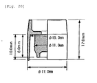
- the structure and dimension of the stopper were shown in Fig. 20 .
- the stopper shown in Fig. 20 has a structure in which a portion 41 which exerts a fitting force onto an external wall surface of the container open end was removed from the stopper shown in Fig. 19 .
- a sealed container (vacuum blood-sampling tube) was obtained in the same manner as Example 1 except that the resulting stopper was used.
- a stopper was manufactured by using the same method as Example 1 except that materials shown in Table 1 were used, and a sealed container (vacuum blood-sampling tube) was obtained by using the same method as Example 1 except that the stopper was used.
- Stopper Container head portion and leg portion B eg portion A structure material deflection temperature under load (0.45MPa)(°C) material deflection temperature under load (0.45MPa)(°C) material
- Example 1 high-impact polystyrene 75 styrene-based thermoplastic elastomer Fig.19 polyethylene terephthalate 69
- Example2 polypropylene 95 EPDM-based thermoplastic elastomer Fig.19 polyethylene terephthalate 69
- Comparative Example2 polypropylene 95 EPDM-based thermoplastic elastomer Fig.20 polyethylene terephthalate 69
- Comparative Example3 low-density polyethylene 45 styrene-based thermoplastic elastomer Fig.20 polyethylene terephthalate 69
- PSJ polystyrene deflection temperature under load (0.45 MPa): about 75°C, manufactured by PS Japan Corporation
- RABALON Styrene-based thermoplastic elastomer
- a stopper was manufactured by using materials shown in Table 3 through a two-material injection-molding method. Here, the structure and dimension of the stopper were shown in Fig. 19 .
- thermoplastic elastomers 0.5% by weight of an oleic acid amide-based lubricant was preliminarily blended in the respective thermoplastic elastomers.
- the stopper was pushed and inserted to the resulting container in a reduced atmospheric pressure state to obtain a sealed container of 6 mL (vacuum blood-sampling tube).
- a stopper was manufactured by using materials shown in Table 3 through a two-material injection-molding method. Here, the structure and dimension of the stopper were shown in Fig. 20 .
- thermoplastic elastomers 0.5% by weight of an oleic acid amide-based lubricant was preliminarily blended in the respective thermoplastic elastomers.
- the stopper was pushed and inserted to the resulting container in a reduced atmospheric pressure state to obtain a sealed container of 6 mL (vacuum blood-sampling tube).
- PSJ polystyrene deflection temperature under load (0.45 MPa): about 75°C, manufactured by PS Japan Corporation
- RABALON Styrene-based thermoplastic elastomer
- NUC high-pressure-method polyethylene deflection temperature under load (0.45 MPa): about 45°C, manufactured by Nippon Unicar Co., Ltd.
- TPX Polymethyl pentene
- the drawing resistance was measured by using the same method as Example 1 immediately after the manufacture and after deformation under heat at 60°C for one week.
- a stopper was manufactured by using materials shown in Table 5 through a two-material injection-molding method. Here, the structure and dimension of the stopper were shown in Fig. 24 .
- thermoplastic elastomers 0.5% by weight of an oleic acid amide-based lubricant was preliminarily blended in the respective thermoplastic elastomers.
- the stopper was pushed and inserted to the resulting container in a reduced atmospheric pressure state to obtain a sealed container of 6 mL (vaccum blood-sampling tube).
- NUC high-pressure-method polyethylene deflection temperature under load (0.45 MPa): about 45°C, manufactured by Nippon Unicar Co., Ltd.
- the drawing resistance was measured by using the same method as Example 1 immediately after the manufacture and after deformation under heat at 60°C for one week.
- the present invention makes it possible to provide a sealed container which comprises a container comprising a thermoplastic resin and a stopper which is hardly slackening even when used in combination with the container, and a vacuum specimen-sampling container comprising the sealed container.
Landscapes
- Health & Medical Sciences (AREA)
- Life Sciences & Earth Sciences (AREA)
- Engineering & Computer Science (AREA)
- General Health & Medical Sciences (AREA)
- Hematology (AREA)
- Veterinary Medicine (AREA)
- Public Health (AREA)
- Animal Behavior & Ethology (AREA)
- Surgery (AREA)
- Heart & Thoracic Surgery (AREA)
- Medical Informatics (AREA)
- Molecular Biology (AREA)
- Biomedical Technology (AREA)
- Pathology (AREA)
- Biophysics (AREA)
- Physics & Mathematics (AREA)
- Chemical & Material Sciences (AREA)
- Manufacturing & Machinery (AREA)
- Analytical Chemistry (AREA)
- Clinical Laboratory Science (AREA)
- Chemical Kinetics & Catalysis (AREA)
- Pharmacology & Pharmacy (AREA)
- Measurement Of The Respiration, Hearing Ability, Form, And Blood Characteristics Of Living Organisms (AREA)
- Medical Preparation Storing Or Oral Administration Devices (AREA)
- Closures For Containers (AREA)
Claims (3)
- Abgedichteter Behälter (1),
der einen Behälter (2), dessen eines Ende geschlossen und dessen anderes Ende offen ist und der ein thermoplastisches Harz beinhaltet, und einen Stopper (10), der lösbar und zum Abdichten des offenen Endes des Behälters fähig ist, umfaßt,
wobei der Stopper (10) einen Kopfabschnitt (20), der gegriffen werden kann, einen Beinabschnitt A (30), der sich von dem Kopfabschnitt (20) nach unten entlang einer inneren Wandoberfläche (4) des offenen Endes des Behälters (2) erstreckt und der eine expandierende Kraft auf die innere Wandoberfläche (4) ausüben kann, und einen Beinabschnitt B (40), der sich von dem Kopfabschnitt (20) nach unten entlang einer äußeren Wandoberfläche (5) des offenen Endes des Behälters (2) erstreckt und der eine Verengungskraft auf die äußere Wandoberfläche (5) ausüben kann, aufweist,
wobei eine Beugungstemperatur unter Last von wenigstens einem Abschnitt des Beinabschnittes B (40) des Stoppers (10), der mit dem Behälter (2) unter einer Last von 0,45 MPa oder 0,46 MPa in Kontakt steht, höher ist als eine Beugungstemperatur unter Last von wenigstens einem Abschnitt des Behälters (2), der mit dem Beinabschnitt A (30) des Stoppers (10) unter einer Last von 0,45 MPa oder 0,46 MPa in Kontakt steht,
wobei ein Abstand des Beinabschnittes B (40) des Stoppers, der mit der äußeren Wandoberfläche (5) des Behälters in Kontakt steht, kürzer ist als ein Abstand des Beinabschnittes A (30) des Stoppers (10), der mit der inneren Wandoberfläche (4) in der Längsrichtung des Behälters in Kontakt steht. - Abgedichteter Behälter nach Anspruch 1,
wobei der Stopper (10) einen Abschnitt (60) zum Einführen eines Nadelrohrs aufweist, der ein thermoplastisches Elastomer oder ein thermohärtendes Elastomer umfaßt. - Vakuumprobensammlungsbehälter,
der einen abgedichteten Behälter (1) nach Anspruch 1 oder 2 umfaßt, wobei sich das innere davon in einem reduzierten Atmosphärendruckzustand befindet.
Applications Claiming Priority (2)
| Application Number | Priority Date | Filing Date | Title |
|---|---|---|---|
| JP2003276989 | 2003-07-18 | ||
| PCT/JP2004/010204 WO2005011495A1 (ja) | 2003-07-18 | 2004-07-16 | 密封容器及び真空検体採取容器 |
Publications (3)
| Publication Number | Publication Date |
|---|---|
| EP1647226A1 EP1647226A1 (de) | 2006-04-19 |
| EP1647226A4 EP1647226A4 (de) | 2009-11-11 |
| EP1647226B1 true EP1647226B1 (de) | 2013-02-13 |
Family
ID=34113756
Family Applications (1)
| Application Number | Title | Priority Date | Filing Date |
|---|---|---|---|
| EP04747670A Expired - Lifetime EP1647226B1 (de) | 2003-07-18 | 2004-07-16 | Hermetisch abgeschlossener behälter und vakuum-testsubstanz-aufnahme-behälter |
Country Status (5)
| Country | Link |
|---|---|
| US (1) | US7726498B2 (de) |
| EP (1) | EP1647226B1 (de) |
| KR (1) | KR101129516B1 (de) |
| CN (1) | CN100508887C (de) |
| WO (1) | WO2005011495A1 (de) |
Families Citing this family (28)
| Publication number | Priority date | Publication date | Assignee | Title |
|---|---|---|---|---|
| AU2005322136B2 (en) * | 2004-12-23 | 2011-01-06 | Hospira, Inc. | Port closure system for intravenous fluid container |
| US7488311B2 (en) * | 2004-12-23 | 2009-02-10 | Hospira, Inc. | Port closure system for intravenous fluid container |
| US7674388B2 (en) | 2005-08-10 | 2010-03-09 | The Regents Of The University Of California | Photopolymer serum separator |
| US9248447B2 (en) * | 2005-08-10 | 2016-02-02 | The Regents Of The University Of California | Polymers for use in centrifugal separation of liquids |
| US7673758B2 (en) | 2005-08-10 | 2010-03-09 | The Regents Of The University Of California | Collection tubes apparatus, systems, and methods |
| US7971730B2 (en) | 2005-08-10 | 2011-07-05 | The Regents Of The University Of California | Collection tubes apparatus, systems and methods |
| US7775962B2 (en) | 2005-08-10 | 2010-08-17 | The Regents Of The University Of California | Centrifuge with polymerizing energy source |
| US9052254B2 (en) | 2006-01-13 | 2015-06-09 | The Bode Technology Group, Inc. | Evidence collector with integral quantified reagents and method of modulating specimen drying time |
| USD651307S1 (en) * | 2007-04-16 | 2011-12-27 | The Bode Technology Group Inc. | Container cap |
| EP2244760B8 (de) * | 2008-01-28 | 2022-07-20 | Implantica Patent Ltd. | Implantierbare drainagevorrichtung |
| CA2717894C (en) | 2008-03-05 | 2014-05-27 | Becton, Dickinson And Company | Capillary action collection device and container assembly |
| CA2718060C (en) | 2008-03-05 | 2015-08-04 | Becton, Dickinson & Company | Co-molded pierceable stopper and method for making same |
| US8460620B2 (en) | 2010-12-03 | 2013-06-11 | Becton, Dickinson And Company | Specimen collection container assembly |
| CN103269955B (zh) * | 2010-12-28 | 2016-03-30 | 尼普洛株式会社 | 小瓶橡胶塞 |
| USD659243S1 (en) * | 2011-01-22 | 2012-05-08 | Sangha Jangbir S | Container cap with hose connector |
| KR101366657B1 (ko) | 2012-05-24 | 2014-02-24 | 김홍곤 | 검체 용기 |
| US20150297800A1 (en) | 2012-07-03 | 2015-10-22 | Sio2 Medical Products, Inc. | SiOx BARRIER FOR PHARMACEUTICAL PACKAGE AND COATING PROCESS |
| US9669405B2 (en) | 2012-10-22 | 2017-06-06 | The Regents Of The University Of California | Sterilizable photopolymer serum separator |
| EP2971228B1 (de) | 2013-03-11 | 2023-06-21 | Si02 Medical Products, Inc. | Beschichtete verpackung |
| CN103435953A (zh) * | 2013-07-29 | 2013-12-11 | 中国科学院长春应用化学研究所 | 用于真空采血管胶塞的热塑性弹性体共混物及其制备方法 |
| US9140527B2 (en) * | 2013-10-11 | 2015-09-22 | Out Rage, Llc | Vibration damping nock construction |
| DE102014205626A1 (de) * | 2014-03-26 | 2015-10-01 | Ford Global Technologies, Llc | Dichtungsvorrichtung |
| ES2760008T3 (es) * | 2014-08-07 | 2020-05-12 | Vinventions Usa Llc | Cierre para un recipiente de retención de producto |
| EP3337915B1 (de) * | 2015-08-18 | 2021-11-03 | SiO2 Medical Products, Inc. | Pharmazeutische und andere verpackungen mit niedriger sauerstoffübertragungsrate |
| EP3356042A1 (de) * | 2015-09-28 | 2018-08-08 | LVL Technologies GmbH & Co. KG | Schraubverschluss für probenröhrchen |
| CN106821397A (zh) * | 2016-12-26 | 2017-06-13 | 江苏康捷医疗器械有限公司 | 一种全自动设备真空血凝管 |
| CN209966387U (zh) * | 2018-05-31 | 2020-01-21 | 深圳迈瑞生物医疗电子股份有限公司 | 用于自动进样的微量样本采集管 |
| KR102574845B1 (ko) * | 2023-03-03 | 2023-09-06 | (주) 메이플엘에스 | 시료 보관용기 |
Citations (1)
| Publication number | Priority date | Publication date | Assignee | Title |
|---|---|---|---|---|
| US6565814B1 (en) * | 1998-03-18 | 2003-05-20 | Sekisui Chemical Co., Ltd. | Closure structure for vacuum specimen collection container, vacuum specimen collection container, vacuum specimen collection system, holder for vacuum specimen collection system and thermoplastic elastomer composition for forming closure structure |
Family Cites Families (51)
| Publication number | Priority date | Publication date | Assignee | Title |
|---|---|---|---|---|
| US3499568A (en) * | 1967-12-28 | 1970-03-10 | Jose Vinas Riera | Stopper system for biological containers |
| US4019646A (en) * | 1975-01-23 | 1977-04-26 | Ricoh Co., Ltd. | Cap with inside stopper for receptacle |
| CH613621A5 (en) | 1976-03-12 | 1979-10-15 | Dematex Dev & Invest | Deformable blocking element for closing a controlled-atmosphere receptacle |
| US4094429A (en) * | 1976-07-26 | 1978-06-13 | Urbin Matthew C | Stopper for test tube, and the like |
| JPS5759536A (en) | 1980-09-27 | 1982-04-09 | Terumo Corp | Rubber gasket for vacuum blood sampling tube |
| US4416661A (en) * | 1981-12-24 | 1983-11-22 | Cutter Laboratories, Inc. | Injection site for fluids |
| ZA825774B (en) | 1982-02-16 | 1983-06-29 | Becton Dickinson Co | Stopper for test tubes, and the like |
| US4569457A (en) * | 1982-03-30 | 1986-02-11 | Yoshida Industry Co., Ltd. | Bottle closure |
| US4465200A (en) * | 1983-06-06 | 1984-08-14 | Becton, Dickinson And Company | Low contamination closure for blood collection tubes |
| AT379069B (de) * | 1984-01-11 | 1985-11-11 | Greiner & Soehne C A | Blutprobenroehrchen |
| AT380392B (de) * | 1985-01-24 | 1986-05-12 | C A Greiner & S Hne Ges M B H | Blutprobenr!hrchen |
| JPS62227316A (ja) | 1986-03-31 | 1987-10-06 | テルモ株式会社 | 採血針 |
| US4697717A (en) * | 1986-08-18 | 1987-10-06 | Becton, Dickinson And Company | Rubber/plastic stopper composite with mechanical adhesive joints |
| WO1988004154A1 (fr) | 1986-12-11 | 1988-06-16 | Terumo Kabushiki Kaisha | Tube de prelevement de sang |
| US4747839A (en) * | 1986-12-17 | 1988-05-31 | Survival Technology, Inc. | Disposable hypodermic syringe with plastic snap-on needle hub and heat shrink seal therefor |
| US4813578A (en) * | 1988-03-11 | 1989-03-21 | International Paper Company | Self opening pour spout and screw cap |
| US5275299A (en) * | 1988-04-15 | 1994-01-04 | C. A. Greiner & Sohne Gesellschaft Mbh | Closure device for an in particular evacuable cylindrical housing |
| US4967919A (en) * | 1988-11-23 | 1990-11-06 | Sherwood Medical Company | Blood collection tube safety cap |
| JPH04501994A (ja) * | 1988-11-28 | 1992-04-09 | ジョセフ パーソンズ ノミニーズ プロプライエタリー リミテッド | キャップ |
| JPH0397450A (ja) | 1989-09-11 | 1991-04-23 | Yukitaka Furukawa | 真空採血管 |
| JPH04279152A (ja) | 1990-01-11 | 1992-10-05 | Charles T Macartney | 生物学的サンプルの採集管 |
| CA2007620A1 (en) * | 1990-02-11 | 1991-07-11 | Charles Terrence Macartney | Biological sample collection tube |
| US5100010A (en) * | 1990-11-08 | 1992-03-31 | The West Company, Incorporated | Containment seal assembly |
| US5219083A (en) * | 1992-04-02 | 1993-06-15 | Sterling Winthrop Inc. | Stopper for reduction of particulate matter |
| AU4999793A (en) * | 1992-08-07 | 1994-03-03 | West Company, Incorporated, The | Needleless access stopper |
| US5494170A (en) | 1993-05-06 | 1996-02-27 | Becton Dickinson And Company | Combination stopper-shield closure |
| US5361921A (en) * | 1993-06-29 | 1994-11-08 | Becton Dickinson And Company | Combination stopper-shield closure |
| JPH0977105A (ja) * | 1995-09-06 | 1997-03-25 | Sanshu:Kk | ビンの開口部の封栓構造 |
| EP0769456B1 (de) * | 1995-10-18 | 2000-08-23 | Daikyo Seiko, Ltd. | Kunststoffkappe und Verfahren zu ihrer Herstellung |
| JP3505320B2 (ja) | 1996-05-27 | 2004-03-08 | シャープ株式会社 | 情報処理装置 |
| US5819964A (en) * | 1996-09-27 | 1998-10-13 | Becton Dickinson And Company | Lyophilization closure assembly for a medicament container for use during a lyophilization process |
| JPH10201742A (ja) | 1997-01-21 | 1998-08-04 | S R L:Kk | 真空採血管のキャップ |
| US5819978A (en) * | 1997-04-24 | 1998-10-13 | Essef Corporation | Two piece composite inlet |
| US6213994B1 (en) * | 1997-09-25 | 2001-04-10 | Becton Dickinson France, S.A. | Method and apparatus for fixing a connector assembly onto a vial |
| US6681946B1 (en) * | 1998-02-26 | 2004-01-27 | Becton, Dickinson And Company | Resealable medical transfer set |
| US6003566A (en) * | 1998-02-26 | 1999-12-21 | Becton Dickinson And Company | Vial transferset and method |
| US6382442B1 (en) * | 1998-04-20 | 2002-05-07 | Becton Dickinson And Company | Plastic closure for vials and other medical containers |
| JP4376339B2 (ja) | 1998-03-18 | 2009-12-02 | 積水化学工業株式会社 | 真空検体採取システム |
| US6378714B1 (en) * | 1998-04-20 | 2002-04-30 | Becton Dickinson And Company | Transferset for vials and other medical containers |
| US6077235A (en) * | 1999-02-23 | 2000-06-20 | Becton, Dickinson And Company | Blood collection assembly and method therefor |
| US6716396B1 (en) * | 1999-05-14 | 2004-04-06 | Gen-Probe Incorporated | Penetrable cap |
| DE60015254T2 (de) * | 1999-08-18 | 2006-02-02 | Becton, Dickinson And Co. | Verschluss bestehend aus einem Stopfen und einer Schutzkappe |
| JP2001149350A (ja) * | 1999-11-25 | 2001-06-05 | Sekisui Chem Co Ltd | 採血管用栓体及び採血管 |
| DE19962664C2 (de) | 1999-12-23 | 2003-01-30 | Helvoet Pharma | Verschlußvorrichtung für einen Unterdruck-Probensammelbehälter |
| DE10007367A1 (de) * | 2000-02-18 | 2001-08-23 | Helvoet Pharma | Verschlusskappe für Infusions- und Transfusionsflaschen |
| JP2002068230A (ja) | 2000-08-25 | 2002-03-08 | Nissui Pharm Co Ltd | キャップ |
| CN1317661A (zh) * | 2001-06-08 | 2001-10-17 | 北京化工大学 | 管子挤胀连接方法及连接组件 |
| US6821267B2 (en) * | 2002-03-07 | 2004-11-23 | Baxter International | Luer tip cap having reduced removal force |
| DE60330100D1 (de) * | 2002-09-20 | 2009-12-31 | Becton Dickinson Co | Rollflasche |
| US20050010175A1 (en) * | 2003-02-27 | 2005-01-13 | Beedon Daniel E. | Piston assembly for syringe |
| US20040256348A1 (en) * | 2003-06-23 | 2004-12-23 | Sonoco Development, Inc. | Flex panel lid or cap |
-
2004
- 2004-07-16 WO PCT/JP2004/010204 patent/WO2005011495A1/ja not_active Ceased
- 2004-07-16 KR KR1020057023546A patent/KR101129516B1/ko not_active Expired - Fee Related
- 2004-07-16 CN CNB2004800206672A patent/CN100508887C/zh not_active Expired - Fee Related
- 2004-07-16 US US10/564,718 patent/US7726498B2/en not_active Expired - Fee Related
- 2004-07-16 EP EP04747670A patent/EP1647226B1/de not_active Expired - Lifetime
Patent Citations (1)
| Publication number | Priority date | Publication date | Assignee | Title |
|---|---|---|---|---|
| US6565814B1 (en) * | 1998-03-18 | 2003-05-20 | Sekisui Chemical Co., Ltd. | Closure structure for vacuum specimen collection container, vacuum specimen collection container, vacuum specimen collection system, holder for vacuum specimen collection system and thermoplastic elastomer composition for forming closure structure |
Also Published As
| Publication number | Publication date |
|---|---|
| US7726498B2 (en) | 2010-06-01 |
| EP1647226A1 (de) | 2006-04-19 |
| WO2005011495A1 (ja) | 2005-02-10 |
| EP1647226A4 (de) | 2009-11-11 |
| CN100508887C (zh) | 2009-07-08 |
| KR20060038945A (ko) | 2006-05-04 |
| CN1822793A (zh) | 2006-08-23 |
| KR101129516B1 (ko) | 2012-03-29 |
| US20060175280A1 (en) | 2006-08-10 |
Similar Documents
| Publication | Publication Date | Title |
|---|---|---|
| EP1647226B1 (de) | Hermetisch abgeschlossener behälter und vakuum-testsubstanz-aufnahme-behälter | |
| US9624015B2 (en) | Septa | |
| US6382441B1 (en) | Plastic tube and resealable closure having protective collar | |
| EP2010847B1 (de) | Kryogener, elastomerer verschluss für kryogene behälter | |
| JP5911433B2 (ja) | 弾性材料から射出成形された一体型フラップデバイス | |
| JP5199398B2 (ja) | 毛管作用採集装置および容器アセンブリ | |
| US8721614B2 (en) | Connector assembly | |
| US11325116B2 (en) | Tip set | |
| JP2000033123A (ja) | コネクタ要素 | |
| EP1707267A1 (de) | Vorrichtung mit selbstdichtendem EInlass | |
| US20150174337A1 (en) | Elastic cap and syringe assembly therewith | |
| CN106659439A (zh) | 具有膜元件的一体式安全管密封件 | |
| CN109415150B (zh) | 冷冻储存容器以及冷冻储存容器系统 | |
| US20170057705A1 (en) | Perforable container cap | |
| CN101932386A (zh) | 提高抽真空样品容器中的真空保持度的组件和方法 | |
| US20040115096A1 (en) | Stopper for tube-shaped specimen containers | |
| JPH11235329A (ja) | 真空検体採取管および真空検体採取方法 | |
| JP4205019B2 (ja) | 密封容器及び真空検体採取容器 | |
| JP5560883B2 (ja) | 真空採血管 | |
| JP2010018307A (ja) | 気密状態持続容器 | |
| KR102574845B1 (ko) | 시료 보관용기 | |
| JP2003169840A (ja) | キャップおよびそれを備える薬液容器 | |
| JPH07204180A (ja) | 採血管ホルダー | |
| JP2010201148A (ja) | 医療用キャップ及びその製造方法 | |
| JP2008295705A (ja) | 採血管用栓体 |
Legal Events
| Date | Code | Title | Description |
|---|---|---|---|
| PUAI | Public reference made under article 153(3) epc to a published international application that has entered the european phase |
Free format text: ORIGINAL CODE: 0009012 |
|
| 17P | Request for examination filed |
Effective date: 20060119 |
|
| AK | Designated contracting states |
Kind code of ref document: A1 Designated state(s): AT BE BG CH CY CZ DE DK EE ES FI FR GB GR HU IE IT LI LU MC NL PL PT RO SE SI SK TR |
|
| DAX | Request for extension of the european patent (deleted) | ||
| A4 | Supplementary search report drawn up and despatched |
Effective date: 20091009 |
|
| 17Q | First examination report despatched |
Effective date: 20091218 |
|
| GRAP | Despatch of communication of intention to grant a patent |
Free format text: ORIGINAL CODE: EPIDOSNIGR1 |
|
| GRAS | Grant fee paid |
Free format text: ORIGINAL CODE: EPIDOSNIGR3 |
|
| GRAA | (expected) grant |
Free format text: ORIGINAL CODE: 0009210 |
|
| AK | Designated contracting states |
Kind code of ref document: B1 Designated state(s): AT BE BG CH CY CZ DE DK EE ES FI FR GB GR HU IE IT LI LU MC NL PL PT RO SE SI SK TR |
|
| REG | Reference to a national code |
Ref country code: GB Ref legal event code: FG4D |
|
| REG | Reference to a national code |
Ref country code: AT Ref legal event code: REF Ref document number: 596038 Country of ref document: AT Kind code of ref document: T Effective date: 20130215 |
|
| REG | Reference to a national code |
Ref country code: IE Ref legal event code: FG4D |
|
| REG | Reference to a national code |
Ref country code: DE Ref legal event code: R096 Ref document number: 602004040972 Country of ref document: DE Effective date: 20130411 |
|
| REG | Reference to a national code |
Ref country code: NL Ref legal event code: T3 |
|
| PG25 | Lapsed in a contracting state [announced via postgrant information from national office to epo] |
Ref country code: SE Free format text: LAPSE BECAUSE OF FAILURE TO SUBMIT A TRANSLATION OF THE DESCRIPTION OR TO PAY THE FEE WITHIN THE PRESCRIBED TIME-LIMIT Effective date: 20130213 Ref country code: ES Free format text: LAPSE BECAUSE OF FAILURE TO SUBMIT A TRANSLATION OF THE DESCRIPTION OR TO PAY THE FEE WITHIN THE PRESCRIBED TIME-LIMIT Effective date: 20130524 Ref country code: CY Free format text: LAPSE BECAUSE OF FAILURE TO SUBMIT A TRANSLATION OF THE DESCRIPTION OR TO PAY THE FEE WITHIN THE PRESCRIBED TIME-LIMIT Effective date: 20130213 Ref country code: BG Free format text: LAPSE BECAUSE OF FAILURE TO SUBMIT A TRANSLATION OF THE DESCRIPTION OR TO PAY THE FEE WITHIN THE PRESCRIBED TIME-LIMIT Effective date: 20130513 |
|
| PG25 | Lapsed in a contracting state [announced via postgrant information from national office to epo] |
Ref country code: FI Free format text: LAPSE BECAUSE OF FAILURE TO SUBMIT A TRANSLATION OF THE DESCRIPTION OR TO PAY THE FEE WITHIN THE PRESCRIBED TIME-LIMIT Effective date: 20130213 Ref country code: GR Free format text: LAPSE BECAUSE OF FAILURE TO SUBMIT A TRANSLATION OF THE DESCRIPTION OR TO PAY THE FEE WITHIN THE PRESCRIBED TIME-LIMIT Effective date: 20130514 Ref country code: PT Free format text: LAPSE BECAUSE OF FAILURE TO SUBMIT A TRANSLATION OF THE DESCRIPTION OR TO PAY THE FEE WITHIN THE PRESCRIBED TIME-LIMIT Effective date: 20130613 Ref country code: SI Free format text: LAPSE BECAUSE OF FAILURE TO SUBMIT A TRANSLATION OF THE DESCRIPTION OR TO PAY THE FEE WITHIN THE PRESCRIBED TIME-LIMIT Effective date: 20130213 Ref country code: PL Free format text: LAPSE BECAUSE OF FAILURE TO SUBMIT A TRANSLATION OF THE DESCRIPTION OR TO PAY THE FEE WITHIN THE PRESCRIBED TIME-LIMIT Effective date: 20130213 |
|
| PG25 | Lapsed in a contracting state [announced via postgrant information from national office to epo] |
Ref country code: RO Free format text: LAPSE BECAUSE OF FAILURE TO SUBMIT A TRANSLATION OF THE DESCRIPTION OR TO PAY THE FEE WITHIN THE PRESCRIBED TIME-LIMIT Effective date: 20130213 Ref country code: SK Free format text: LAPSE BECAUSE OF FAILURE TO SUBMIT A TRANSLATION OF THE DESCRIPTION OR TO PAY THE FEE WITHIN THE PRESCRIBED TIME-LIMIT Effective date: 20130213 Ref country code: EE Free format text: LAPSE BECAUSE OF FAILURE TO SUBMIT A TRANSLATION OF THE DESCRIPTION OR TO PAY THE FEE WITHIN THE PRESCRIBED TIME-LIMIT Effective date: 20130213 Ref country code: DK Free format text: LAPSE BECAUSE OF FAILURE TO SUBMIT A TRANSLATION OF THE DESCRIPTION OR TO PAY THE FEE WITHIN THE PRESCRIBED TIME-LIMIT Effective date: 20130213 Ref country code: CZ Free format text: LAPSE BECAUSE OF FAILURE TO SUBMIT A TRANSLATION OF THE DESCRIPTION OR TO PAY THE FEE WITHIN THE PRESCRIBED TIME-LIMIT Effective date: 20130213 |
|
| PLBE | No opposition filed within time limit |
Free format text: ORIGINAL CODE: 0009261 |
|
| STAA | Information on the status of an ep patent application or granted ep patent |
Free format text: STATUS: NO OPPOSITION FILED WITHIN TIME LIMIT |
|
| 26N | No opposition filed |
Effective date: 20131114 |
|
| BERE | Be: lapsed |
Owner name: SEKISUI CHEMICAL CO., LTD. Effective date: 20130731 |
|
| REG | Reference to a national code |
Ref country code: NL Ref legal event code: V1 Effective date: 20140201 |
|
| REG | Reference to a national code |
Ref country code: DE Ref legal event code: R097 Ref document number: 602004040972 Country of ref document: DE Effective date: 20131114 |
|
| PG25 | Lapsed in a contracting state [announced via postgrant information from national office to epo] |
Ref country code: MC Free format text: LAPSE BECAUSE OF FAILURE TO SUBMIT A TRANSLATION OF THE DESCRIPTION OR TO PAY THE FEE WITHIN THE PRESCRIBED TIME-LIMIT Effective date: 20130213 |
|
| REG | Reference to a national code |
Ref country code: CH Ref legal event code: PL |
|
| GBPC | Gb: european patent ceased through non-payment of renewal fee |
Effective date: 20130716 |
|
| REG | Reference to a national code |
Ref country code: IE Ref legal event code: MM4A |
|
| REG | Reference to a national code |
Ref country code: DE Ref legal event code: R119 Ref document number: 602004040972 Country of ref document: DE Effective date: 20140201 |
|
| REG | Reference to a national code |
Ref country code: FR Ref legal event code: ST Effective date: 20140331 |
|
| PG25 | Lapsed in a contracting state [announced via postgrant information from national office to epo] |
Ref country code: GB Free format text: LAPSE BECAUSE OF NON-PAYMENT OF DUE FEES Effective date: 20130716 Ref country code: BE Free format text: LAPSE BECAUSE OF NON-PAYMENT OF DUE FEES Effective date: 20130731 Ref country code: DE Free format text: LAPSE BECAUSE OF NON-PAYMENT OF DUE FEES Effective date: 20140201 Ref country code: NL Free format text: LAPSE BECAUSE OF NON-PAYMENT OF DUE FEES Effective date: 20140201 Ref country code: CH Free format text: LAPSE BECAUSE OF NON-PAYMENT OF DUE FEES Effective date: 20130731 Ref country code: LI Free format text: LAPSE BECAUSE OF NON-PAYMENT OF DUE FEES Effective date: 20130731 |
|
| PG25 | Lapsed in a contracting state [announced via postgrant information from national office to epo] |
Ref country code: FR Free format text: LAPSE BECAUSE OF NON-PAYMENT OF DUE FEES Effective date: 20130731 Ref country code: IT Free format text: LAPSE BECAUSE OF NON-PAYMENT OF DUE FEES Effective date: 20130716 |
|
| PG25 | Lapsed in a contracting state [announced via postgrant information from national office to epo] |
Ref country code: IE Free format text: LAPSE BECAUSE OF NON-PAYMENT OF DUE FEES Effective date: 20130716 |
|
| REG | Reference to a national code |
Ref country code: AT Ref legal event code: MM01 Ref document number: 596038 Country of ref document: AT Kind code of ref document: T Effective date: 20130716 |
|
| PG25 | Lapsed in a contracting state [announced via postgrant information from national office to epo] |
Ref country code: AT Free format text: LAPSE BECAUSE OF NON-PAYMENT OF DUE FEES Effective date: 20130716 |
|
| PG25 | Lapsed in a contracting state [announced via postgrant information from national office to epo] |
Ref country code: TR Free format text: LAPSE BECAUSE OF FAILURE TO SUBMIT A TRANSLATION OF THE DESCRIPTION OR TO PAY THE FEE WITHIN THE PRESCRIBED TIME-LIMIT Effective date: 20130213 |
|
| PG25 | Lapsed in a contracting state [announced via postgrant information from national office to epo] |
Ref country code: LU Free format text: LAPSE BECAUSE OF NON-PAYMENT OF DUE FEES Effective date: 20130716 Ref country code: HU Free format text: LAPSE BECAUSE OF FAILURE TO SUBMIT A TRANSLATION OF THE DESCRIPTION OR TO PAY THE FEE WITHIN THE PRESCRIBED TIME-LIMIT; INVALID AB INITIO Effective date: 20040716 |