EP1648011A2 - Limiteur de surcharge d'un moteur - Google Patents
Limiteur de surcharge d'un moteur Download PDFInfo
- Publication number
- EP1648011A2 EP1648011A2 EP05254746A EP05254746A EP1648011A2 EP 1648011 A2 EP1648011 A2 EP 1648011A2 EP 05254746 A EP05254746 A EP 05254746A EP 05254746 A EP05254746 A EP 05254746A EP 1648011 A2 EP1648011 A2 EP 1648011A2
- Authority
- EP
- European Patent Office
- Prior art keywords
- terminal
- recess
- base
- wall
- movable contact
- Prior art date
- Legal status (The legal status is an assumption and is not a legal conclusion. Google has not performed a legal analysis and makes no representation as to the accuracy of the status listed.)
- Granted
Links
Images









Classifications
-
- H—ELECTRICITY
- H02—GENERATION; CONVERSION OR DISTRIBUTION OF ELECTRIC POWER
- H02H—EMERGENCY PROTECTIVE CIRCUIT ARRANGEMENTS
- H02H7/00—Emergency protective circuit arrangements specially adapted for specific types of electric machines or apparatus or for sectionalised protection of cable or line systems, and effecting automatic switching in the event of an undesired change from normal working conditions
- H02H7/08—Emergency protective circuit arrangements specially adapted for specific types of electric machines or apparatus or for sectionalised protection of cable or line systems, and effecting automatic switching in the event of an undesired change from normal working conditions for dynamo-electric motors
-
- H—ELECTRICITY
- H01—ELECTRIC ELEMENTS
- H01H—ELECTRIC SWITCHES; RELAYS; SELECTORS; EMERGENCY PROTECTIVE DEVICES
- H01H9/00—Details of switching devices, not covered by groups H01H1/00 - H01H7/00
- H01H9/02—Bases, casings, or covers
- H01H9/04—Dustproof, splashproof, drip-proof, waterproof, or flameproof casings
- H01H9/042—Explosion-proof cases
-
- H—ELECTRICITY
- H01—ELECTRIC ELEMENTS
- H01H—ELECTRIC SWITCHES; RELAYS; SELECTORS; EMERGENCY PROTECTIVE DEVICES
- H01H37/00—Thermally-actuated switches
- H01H37/02—Details
- H01H37/32—Thermally-sensitive members
- H01H37/52—Thermally-sensitive members actuated due to deflection of bimetallic element
- H01H37/54—Thermally-sensitive members actuated due to deflection of bimetallic element wherein the bimetallic element is inherently snap acting
- H01H37/5427—Thermally-sensitive members actuated due to deflection of bimetallic element wherein the bimetallic element is inherently snap acting encapsulated in sealed miniaturised housing
-
- H—ELECTRICITY
- H01—ELECTRIC ELEMENTS
- H01H—ELECTRIC SWITCHES; RELAYS; SELECTORS; EMERGENCY PROTECTIVE DEVICES
- H01H61/00—Electrothermal relays
- H01H61/002—Structural combination of a time delay electrothermal relay with an electrothermal protective relay, e.g. a start relay
-
- F—MECHANICAL ENGINEERING; LIGHTING; HEATING; WEAPONS; BLASTING
- F25—REFRIGERATION OR COOLING; COMBINED HEATING AND REFRIGERATION SYSTEMS; HEAT PUMP SYSTEMS; MANUFACTURE OR STORAGE OF ICE; LIQUEFACTION SOLIDIFICATION OF GASES
- F25B—REFRIGERATION MACHINES, PLANTS OR SYSTEMS; COMBINED HEATING AND REFRIGERATION SYSTEMS; HEAT PUMP SYSTEMS
- F25B2400/00—Component parts or details not otherwise provided for in this subclass
- F25B2400/07—Details of compressors or related parts
- F25B2400/077—Compressor control units, e.g. terminal boxes, mounted on the compressor casing wall containing for example starter, protection switches or connector contacts
Definitions
- This invention relates generally to motor protectors and more particularly to electrical enclosed break devices.
- U.S. Patent No. 4,706,152 assigned to Texas Instruments Incorporated, relates to an enclosed break device known as the 4TM and the 5TM.
- An enclosed break device according to the International Electrotechnical Commission (IEC) Standard 60079-15 second edition 2001-02, is a "device incorporating electrical contacts that are made and broken and that will withstand an internal explosion of the flammable gas or vapor which may enter it without suffering damage and without communicating the internal explosion to the external flammable gas or vapor.”
- the 4TM and 5TM devices which have been made in accordance with the referenced patent comply with the first edition of the IEC standard 60079-15 which requires that enclosed break devices pass a make-and-break test 3 times without communicating an internal explosion to external flammable gas or vapor. However, such devices may not meet the requirement of the second edition IEC Standard 60079-15, which requires that an enclosed break device pass a make-and-break test 10 times.
- Another object of the invention is the provision of an internal break device that can be subjected to a make-and-break test ten times without communicating an internal explosion to external flammable gas or vapor.
- a conventional 4TM/5TM type device comprises a base of electrically insulative material in which an elongated recess is formed.
- a first terminal is mounted at a first end and provided with a contact mounting portion disposed within the recess with a stationary contact mounted thereon.
- An elongated movable contact arm has a first end fixedly mounted on a mounting portion connected to another terminal.
- a movable contact is mounted on a free end of the movable contact arm and is arranged to move into and out of engagement with the stationary contact.
- a well is formed intermediate to the ends of the elongated recess and a heater is disposed therein in heat transfer relation to a thermostatic disc seated in the base over the well.
- the disc is adapted to snap from one dished configuration to an opposite dished configuration upon being heated to a preselected temperature. When the disc snaps it transfers motion to the movable contact arm causing the movable contact to move out of engagement with the stationary contact thereby interrupting the circuit path therethrough.
- a cover of electrically insulative material is received on the base to enclose the switch mechanism.
- the first path is shown by lines 2a of Figs. 3 and 6 which extend directly from the contacts through slots/openings between the first terminal blade portion and the side walls of the slots/openings of the base and the cover.
- the second path is shown by lines 2b (Fig. 3) which extends from the contacts over the wall at the back portion of the contact receiving end of the recess.
- the cover is modified by forming first and second multiple wall barriers to impede the travel of arcs from the make-and-break contacts.
- the first multiple wall barrier comprises spaced apart wall portions which are received on the mounting portion of the first terminal closely adjacent to the stationary and movable contacts.
- the wall portions form a generally triangular configuration with respect to a cross section taken parallel to the bottom wall of the base. This structure also serves to decrease the volume of space between the base and cover thereby minimizing the supply of fuel to an internal explosion.
- a vertically extending notch is formed in the walls which interfit with a corner portion of a corresponding side wall of the base to further inhibit arc travel.
- the second multiple wall barrier comprises another set of spaced apart wall portions along the perimeter of the base at a side of the first end of the recess to limit travel of arcing from the contacts and to further decrease excess volume of space.
- the various openings formed in the housing of the device are sealed by epoxy to prevent propagation of any internal explosion from external flammable gas.
- the sealing can be utilized by itself or along with the cover modifications noted above.
- Fig. 1 is a perspective view of a 4TM/5TM device taken from above the device;
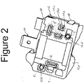
- Fig. 2 is a perspective view of the Fig. 1 device taken from the same position but with the device rotated half a turn upwardly into the paper as seen in Fig. 1;
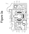
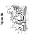
- Fig. 3a is a top plan view of the base of the device prior to the installation of components therein and Fig. 3b is a view similar to Fig. 3a shown at a slight angle relative to the position of Fig. 3a to better illustrate the relative heights of the various surfaces of the base;
- Fig. 4 is a perspective view of the cover of the Fig. 1 device as it existed prior to the instant invention taken generally in the Fig. 2 orientation;
- Fig. 5a is a top plan view of the Fig. 1 device as it existed prior to the instant invention with the cover removed;
- Fig. 5b is the same as Fig. 5a but with the snap acting disc removed for purposes of illustration;
- Fig. 5c is the same as Fig. 5a but with the disc and heater element removed for purposes of illustration;
- Fig. 6 is a broken away cross section in the direction of a front elevational view of Figs. 5a-5c device taken through the make-and-break contacts;
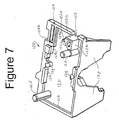
- Fig. 7 is a view similar to Fig. 4 of a cover made in accordance with a preferred embodiment of the invention.
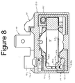
- Fig. 8 is a view similar to Fig. 5a but is shown with a cover in a horizontal cross section, the cover incorporating the preferred embodiment shown in Fig. 7;
- Fig. 9 is a top plan view of a 4TM and 5TM device made in accordance with the preferred embodiment of Figs. 7 and 8;
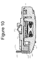
- Fig. 10 is an elevational cross section taken on line 10-10 of Fig. 9;
- Fig. 11 is an elevational cross section taken on line 11-11 of Fig. 9;
- Fig. 12 is an elevational cross section taken on line 12-12 of Fig. 9;
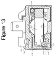
- Fig. 13 is a view similar to Fig. 8 but showing an alternative preferred embodiment of the invention.
- Fig. 14 is a perspective view, similar to Fig. 1 of a device made in accordance with the Fig. 13 preferred embodiment;
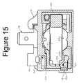
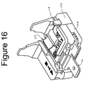
- Fig. 15 is a perspective view, similar to Figs. 8 and 13 showing another alternative preferred embodiment of the invention.
- Fig. 16 is a view similar to Fig. 15 of a device made according to the Fig. 15 embodiment.
- the 4TM and 5TM devices referenced above comprise a housing having a generally rectangular base 10 having a major length along the front of the device and a minor length from front to back of the device.
- a recess 10a is formed in the base and a cover 12 is received thereon closing the recess.
- First and second guide pin holes 10t, 10u are formed in the bottom wall for reception of cover guide pins 12d, 12e, respectively, to be discussed.
- recess 10a is generally elongated in the direction of the major length having a contact receiving end 10b, an opposite movable contact arm mounting end 10c and a central heater receiving portion 10d intermediate to the two ends.
- Contact receiving end 10b of the recess is defined by side wall portions 10e on the front, and 10e and 10el tapered downwardly from line 10gl on the left side of the base as seen in Fig. 3 with an offset lower seating ledge 10f contiguous with these portions on the front and left sides.
- the back side of the contact receiving end of the recess is defined by wall portion 10e with a downward tapered portion extending from line 10g on to the right extreme of that wall portion as viewed in Fig. 3. As will be discussed below, there is no seating ledge along the back portion of the contact receiving end of the recess. Outboard of the back side of the contact receiving end of the recess defining wall is a downwardly spaced terminal receiving ledge 10h.
- Central heater receiving portion 10d is defined on the front by a downwardly offset portion 10k along with an outer downwardly further offset ledge 10m and on the back side by wall portion 10f.
- Outboard of wall portion 10f defining the central heater receiving portion 10d of the recess is another terminal receiving ledge 10n offset further downwardly than terminal receiving ledge 10h, i.e., ledge 10n is closer to the bottom wall of the base than is ledge 10h.
- the movable contact arm mounting end 10c of the recess is defined by side wall 10e with outer wall portion 10f serving as a seating ledge.
- a slot 10o is formed in side wall 10e defining the left side of contact receiving end 10b of the recess for reception of a first terminal 14 to be discussed.
- a second terminal 16 has a base portion 16a received on ledge 10n and has a transversely extending step portion 16b extending up to a higher level to a body portion 16c.
- a separate electrically conductive terminal strip 16d is received on terminal receiving ledge 10h and is provided with a transversely extending step portion 16e extending down to the bottom of the central heater receiving recess portion in a space 10r between wall portion 10f defining the back of the central heater receiving portion of the recess and the central heater receiving portion of the recess 10d with the end 16f of strip portion 16d serving as a connection location for one end 20a of a heater 20, to be discussed, disposed in an annular well 10q in the recess.
- the body portion 16c of the second terminal 16 is fixedly and electrically connected to terminal strip 16d on ledge portion 10h, as by welding.
- First terminal 14 has a first, generally flat mounting portion 14a disposed at the contact receiving end 10b of recess 10a, an arm 14d which projects downwardly through an opening 10w in the bottom wall of the base and formed with a pair of clamping fingers 14e which are spread apart after being received through opening 10w to secure the mounting portion.
- First terminal 14 has a second portion 14b that includes an interconnection blade portion extending out of an opening in the side wall of the housing.
- a movable contact 18a is mounted on the bottom surface of movable contact arm 18 at its free end and is arranged to move into and out of electrical engagement with a stationary contact 14c mounted on mounting portion 14a of the first terminal.
- a third pin receiving terminal 24 (Fig. 1) has a body portion 24a received on the top surface of cover 12 with pin receiving portion 24b aligned with the space between ears 12p of the cover. Terminal 24 has an arm 24c which extends over to the blade portion 14b of first terminal 14 and is electrically connected thereto, as by welding.
- heater 20 (see Fig. 5b) is disposed in well 10q of central heater receiving portion 10d of recess 10a and a thermostatic, snap acting disc 22 (see Fig. 5a) is received on a disc seat formed in that portion of recess 10d so that the disc is above the heater in heat transfer relation therewith.
- Disc 22 is arranged so that at normal ambient temperature the disc is in a first dished shape configuration out of engagement with movable contact arm 18 however, upon reaching a predetermined actuation temperature, the disc snaps to a second, opposite dished configuration engaging dimple 18c of movable contact arm 18 and moves the movable contact 18a out of engagement with stationary contact 14c thereby opening the electrical path between terminals 16 and 18.
- Cover 12 shown best in Fig. 4 and shown inverted relative to Fig. 1, is formed with a recess closing wall 12a and side walls 12b formed generally around the outer perimeter of recess closing wall 12a and extend orthogonally therefrom side walls 12b are alignable with seating ledge portion 10f of side walls 10e of base 10.
- a slot or opening 12c formed in side wall 12b extends into recess closing wall 12a and is alignable with slot or-opening 10o in the base, to provide access for blade portion 14b of terminal 14.
- First and second alignment posts 12d, 12e, respectively, extend orthogonally from recess closing wall 12a and are adapted to be received in matching bores 10t, 10u, respectively, in base 10.
- Side wall 12b is extended in height at central front portion 12f and is adapted to be received on seating ledge 10m of the base, i.e., extending beyond wall portion 10k to provide an interdigitated or closed fit with wall portion 12f received in a step between wall portion 10k and 10m.
- first and second disc retaining pins 12g disposed at opposed locations alignable with outer peripheral portions of the disc seat.
- First and second elongated blocks 12h are formed on wall 12a extending along the major wall length contiguous with side wall 12b on either side of one of the disc retaining pins and extending in height beyond side wall 12b.
- protectors made as shown in Figs. 1-5 have performed extremely well and have been widely used in various industries, certain aspects of the devices need to be modified to ensure that the devices comply with recent changes in the requirements of the International Electrotechnical Commission Standard relating to "enclosed break devices" discussed above.
- Figs. 3, 5a-5c and 6 there are two paths leading from contacts 18a, 14c to openings at locations between the cover and the base where the cover side wall is not interdigitated with the base, or closed, with a notched seating ledge of the base, or the like. These locations allow flammable gas outside the protector housing to enter into the housing and enable internal arcing to ignite the flammable gas outside the device.
- the first path is shown by lines 2a (Figs.
- a modified cover 120 made in accordance with a first feature of a preferred embodiment of the invention comprises a first multiple wall barrier 122 extending from recess closing wall 12a comprising a first wall 122a orthogonally from wall 12a and disposed so that it is essentially flush with the inner surface of terminal receiving slot 10o and extends from the recess closing wall 12a generally to horizontally extending flat portion 14b of terminal 14 when the cover is received on the base (see Fig. 10).
- a second wall 122b which extends over to guide pin 12e and then a third wall 122c extends between the extremity of wall 122a and post 12e generally forming a triangular barrier wall that extends normally from recess closing wall 12a that not only serves to interrupt arc travel but also reduces the volume of free space between the cover and the base, that is, it reduces the amount of fuel for supporting combustion.
- a notch 122d (Fig. 8), extending in a normal direction to recess closing wall 12a is formed in walls 122a and 122c at their intersection that is adapted to receive the side wall 10e of the base to further impede arc travel.
- a portion of wall barrier 122 along wall 122c that forms notch 122d is extended at 122e a distance essentially the same as the thickness of a mounting portion 14a of terminal 14.
- this extension, or knob is received in a small open space next to mounting portion 14a extending toward opening 10t.
- This triangular feature essentially closes off the first path 2a of arc travel.
- a second multiple wall barrier 124 is formed in the cover so that when placed on the base the barrier is at the first end of the housing adjacent to contacts 14c, 18a along the outer periphery.
- the second barrier adds wall 124a which extends normal to recess closing wall 12a and generally parallel to side wall 12b relative to the major length of the elongated base and spaced therefrom.
- Wall 124a extends away from recess closing wall 12a a distance essentially the same as outer wall 12b.
- Wall 124a at its extremity away from side wall 12b on the minor length end of the cover is joined to side wall 12b on the major length side by wall 124b of the same height.
- Block 124c Contiguous to barrier 124 and extending along side wall 12b in the direction of its longitudinal axis, i.e., major length, is a block 124c, preferably formed of the same material as the cover, the block extending vertically a distance greater than that of side wall 12b.
- Block 124c serves as an arc barrier filling in the space 10r between wall portion 10e, 10e1 adjacent to stop 16e of conductive strip 16d defined by the back part of the contact receiving recess and wall portion 10f in back of the central heater receiving portion of the recess.
- terminal portion 14b can be moved inwardly away from the outer periphery of the housing as seen in Figs. 13 and 14 with side wall portions 10e' and 12b' being continuous, that is, without slot 10o and 12c being formed in the side walls with wall 122a of the first barrier 122 essentially butted up against side wall 10e just beyond slot 100.
- barrier 122 if desired, could be formed without notch 122d with barrier wall 122a butted up against sidewall 10e just beyond slot 10o.
- the Fig. 1 structure can be modified by forming side wall portion 126 to extend across slot 10o externally thereof.
- the location of terminal 14 can remain as shown in Fig. 8 with a side wall 126 covering the slot 10o, 12c in side walls 10e of the base and 12b of the cover, respectively.
- each of these openings can be sealed with suitable epoxy. This can be done along with the above embodiments or in place of them, as desired.
Landscapes
- Physics & Mathematics (AREA)
- Thermal Sciences (AREA)
- Switch Cases, Indication, And Locking (AREA)
- Connector Housings Or Holding Contact Members (AREA)
- Thermally Actuated Switches (AREA)
- Arc-Extinguishing Devices That Are Switches (AREA)
Applications Claiming Priority (1)
| Application Number | Priority Date | Filing Date | Title |
|---|---|---|---|
| US61808304P | 2004-10-12 | 2004-10-12 |
Publications (3)
| Publication Number | Publication Date |
|---|---|
| EP1648011A2 true EP1648011A2 (fr) | 2006-04-19 |
| EP1648011A3 EP1648011A3 (fr) | 2007-08-15 |
| EP1648011B1 EP1648011B1 (fr) | 2010-02-24 |
Family
ID=35618466
Family Applications (1)
| Application Number | Title | Priority Date | Filing Date |
|---|---|---|---|
| EP05254746A Expired - Lifetime EP1648011B1 (fr) | 2004-10-12 | 2005-07-28 | Limiteur de surcharge d'un moteur |
Country Status (6)
| Country | Link |
|---|---|
| US (1) | US7304561B2 (fr) |
| EP (1) | EP1648011B1 (fr) |
| JP (1) | JP4794243B2 (fr) |
| KR (1) | KR100967865B1 (fr) |
| CN (2) | CN1773648B (fr) |
| DE (1) | DE602005019513D1 (fr) |
Cited By (1)
| Publication number | Priority date | Publication date | Assignee | Title |
|---|---|---|---|---|
| CN101320661B (zh) * | 2007-06-07 | 2011-04-20 | 森萨塔科技韩国有限公司 | 具有防爆结构的过载保护器 |
Families Citing this family (4)
| Publication number | Priority date | Publication date | Assignee | Title |
|---|---|---|---|---|
| US7304561B2 (en) * | 2004-10-12 | 2007-12-04 | Sensata Technologies, Inc. | Motor overload protector |
| KR20070076008A (ko) * | 2006-01-17 | 2007-07-24 | 센서스앤드컨트롤스코리아 주식회사 | 개선된 폭발 방지 구조를 갖는 과부하 보호 장치 |
| US7622835B2 (en) * | 2007-01-26 | 2009-11-24 | Sensata Technologies Massachusetts, Inc. | Motor protector attachment system |
| TWI403741B (zh) * | 2010-04-30 | 2013-08-01 | Au Optronics Corp | 測試裝置 |
Citations (1)
| Publication number | Priority date | Publication date | Assignee | Title |
|---|---|---|---|---|
| US4706152A (en) | 1985-03-15 | 1987-11-10 | Texas Instruments Incorporated | Protected refrigerator compressor motor systems and motor protectors therefor |
Family Cites Families (23)
| Publication number | Priority date | Publication date | Assignee | Title |
|---|---|---|---|---|
| US3579167A (en) | 1966-07-20 | 1971-05-18 | Texas Instruments Inc | Thermostatic switch with improved heater assembly and method of assembling same |
| US3452313A (en) * | 1966-12-19 | 1969-06-24 | Texas Instruments Inc | Snap-acting thermostatic electric switch |
| US3564185A (en) * | 1969-02-24 | 1971-02-16 | Robertshaw Controls Co | Electrical switch construction with shield |
| US3601568A (en) * | 1969-12-15 | 1971-08-24 | Carling Electric Inc | Arc-trapping improvement for electric switch cases |
| US3590174A (en) * | 1970-03-26 | 1971-06-29 | Gutler Hammer Inc | Arc shield for rotary electrical switch |
| US3959762A (en) * | 1974-12-09 | 1976-05-25 | Texas Instruments Incorporated | Thermally responsive electrical switch |
| DE2604764C3 (de) | 1976-02-07 | 1978-08-03 | Danfoss A/S, Nordborg (Daenemark) | Elektrische Anschlußvorrichtung für eine gekapselte Kältemaschine |
| JPS623851Y2 (fr) * | 1978-09-01 | 1987-01-28 | ||
| ES247088U (es) * | 1979-11-13 | 1980-03-16 | Enrique Garrell Alsina Sa | Interruptor magnetotermico |
| US4551701A (en) * | 1984-05-17 | 1985-11-05 | Susumu Ubukata | Thermally actuated switching device |
| US4555686A (en) * | 1984-05-29 | 1985-11-26 | Texas Instruments Incorporated | Snap-acting thermostatic switch assembly |
| US4812799A (en) * | 1987-04-02 | 1989-03-14 | Texas Instruments Incorporated | Miniature circuit breaker with improved longevity |
| US4837545A (en) * | 1987-04-02 | 1989-06-06 | Texas Instruments Incorporated | Miniature circuit breaker with improved longevity |
| US4827233A (en) * | 1987-04-02 | 1989-05-02 | Texas Instruments Incorporated | Miniature circuit breaker with improved longivity |
| US4780697A (en) * | 1987-04-02 | 1988-10-25 | Texas Instruments Incorporated | Miniature circuit breaker with improved longevity |
| JPH0212138U (fr) * | 1988-07-05 | 1990-01-25 | ||
| US4937548A (en) * | 1989-10-25 | 1990-06-26 | Mechanical Products, Inc. | Circuit breaker |
| JP2519549B2 (ja) * | 1989-12-26 | 1996-07-31 | 生方 眞哉 | 熱応動開閉器 |
| KR100231796B1 (ko) | 1995-11-07 | 1999-12-01 | 무라타 야스타카 | 고장시에 내부 소자의 파괴를 줄이는 전자 장치 |
| JPH1131445A (ja) | 1997-07-10 | 1999-02-02 | Texas Instr Japan Ltd | スイッチ装置 |
| JP4338332B2 (ja) * | 2001-03-02 | 2009-10-07 | ウチヤ・サーモスタット株式会社 | サーマルプロテクタ |
| JP4097511B2 (ja) * | 2002-11-21 | 2008-06-11 | 山田電機製造株式会社 | サーマルプロテクタ、サーマルプロテクタを用いた密閉形電動圧縮機及びこれを用いる機器 |
| US7304561B2 (en) * | 2004-10-12 | 2007-12-04 | Sensata Technologies, Inc. | Motor overload protector |
-
2005
- 2005-07-12 US US11/179,141 patent/US7304561B2/en not_active Expired - Lifetime
- 2005-07-28 EP EP05254746A patent/EP1648011B1/fr not_active Expired - Lifetime
- 2005-07-28 DE DE602005019513T patent/DE602005019513D1/de not_active Expired - Lifetime
- 2005-08-09 KR KR1020050072897A patent/KR100967865B1/ko not_active Expired - Fee Related
- 2005-09-06 JP JP2005257330A patent/JP4794243B2/ja not_active Expired - Fee Related
- 2005-09-15 CN CN2005101040789A patent/CN1773648B/zh not_active Expired - Fee Related
- 2005-09-15 CN CNU2005201223304U patent/CN2862462Y/zh not_active Expired - Fee Related
Patent Citations (1)
| Publication number | Priority date | Publication date | Assignee | Title |
|---|---|---|---|---|
| US4706152A (en) | 1985-03-15 | 1987-11-10 | Texas Instruments Incorporated | Protected refrigerator compressor motor systems and motor protectors therefor |
Cited By (1)
| Publication number | Priority date | Publication date | Assignee | Title |
|---|---|---|---|---|
| CN101320661B (zh) * | 2007-06-07 | 2011-04-20 | 森萨塔科技韩国有限公司 | 具有防爆结构的过载保护器 |
Also Published As
| Publication number | Publication date |
|---|---|
| US20060077610A1 (en) | 2006-04-13 |
| EP1648011B1 (fr) | 2010-02-24 |
| KR100967865B1 (ko) | 2010-07-05 |
| CN2862462Y (zh) | 2007-01-24 |
| DE602005019513D1 (de) | 2010-04-08 |
| JP4794243B2 (ja) | 2011-10-19 |
| US7304561B2 (en) | 2007-12-04 |
| CN1773648B (zh) | 2011-12-21 |
| EP1648011A3 (fr) | 2007-08-15 |
| JP2006114488A (ja) | 2006-04-27 |
| CN1773648A (zh) | 2006-05-17 |
| KR20060050345A (ko) | 2006-05-19 |
Similar Documents
| Publication | Publication Date | Title |
|---|---|---|
| US7075403B2 (en) | Motor protector particularly useful with hermetic electromotive compressors | |
| US5607610A (en) | Compact protector | |
| US6503647B1 (en) | Battery protection device and method of making same | |
| US5995351A (en) | Motor protector device | |
| CN100396925C (zh) | 封闭式压缩机的保护装置和利用该装置的封闭式压缩机 | |
| KR101241629B1 (ko) | 열응동 개폐기 | |
| JP2005129471A (ja) | サーマルプロテクタ | |
| KR20050021306A (ko) | 모터 시동 릴레이 및 이것을 이용한 전기 컴프레서 | |
| US7102481B2 (en) | Low current electric motor protector | |
| EP1648011B1 (fr) | Limiteur de surcharge d'un moteur | |
| US3431526A (en) | Miniature electrical switch | |
| JP3257680B2 (ja) | 熱応動スイッチ及びその製作方法 | |
| US7109840B2 (en) | Protector for electrical apparatus | |
| JPH0617780A (ja) | 密閉形電動圧縮機 | |
| US3148256A (en) | Snap action thermostatic switches | |
| US20030210502A1 (en) | Internal motor protector for hermetic compressor | |
| JPH06307374A (ja) | 密閉形電動圧縮機 | |
| US20060205248A1 (en) | Voltmeter relay with shaped base which contains slots designed to form seatings for the insertion of "faston" connectors | |
| JP2858001B2 (ja) | サーマルプロテクタ | |
| KR20070076008A (ko) | 개선된 폭발 방지 구조를 갖는 과부하 보호 장치 | |
| JP3143298B2 (ja) | 漏電遮断器 | |
| US3470514A (en) | Electrical switch particularly adapted for use in pressurized areas | |
| KR100317913B1 (ko) | 밀폐형 왕복동식 압축기의 오버로드 프로텍터 | |
| JPH0547278A (ja) | 熱応動スイツチ | |
| KR19980032811U (ko) | 전지팩용 서모스탯 |
Legal Events
| Date | Code | Title | Description |
|---|---|---|---|
| PUAI | Public reference made under article 153(3) epc to a published international application that has entered the european phase |
Free format text: ORIGINAL CODE: 0009012 |
|
| AK | Designated contracting states |
Kind code of ref document: A2 Designated state(s): AT BE BG CH CY CZ DE DK EE ES FI FR GB GR HU IE IS IT LI LT LU LV MC NL PL PT RO SE SI SK TR |
|
| AX | Request for extension of the european patent |
Extension state: AL BA HR MK YU |
|
| RAP1 | Party data changed (applicant data changed or rights of an application transferred) |
Owner name: SENSATA TECHNOLOGIES, INC. |
|
| PUAL | Search report despatched |
Free format text: ORIGINAL CODE: 0009013 |
|
| AK | Designated contracting states |
Kind code of ref document: A3 Designated state(s): AT BE BG CH CY CZ DE DK EE ES FI FR GB GR HU IE IS IT LI LT LU LV MC NL PL PT RO SE SI SK TR |
|
| AX | Request for extension of the european patent |
Extension state: AL BA HR MK YU |
|
| 17P | Request for examination filed |
Effective date: 20071026 |
|
| 17Q | First examination report despatched |
Effective date: 20071213 |
|
| AKX | Designation fees paid |
Designated state(s): DE FR GB |
|
| RAP1 | Party data changed (applicant data changed or rights of an application transferred) |
Owner name: SENSATA TECHNOLOGIES MASSACHUSETTS, INC. |
|
| GRAC | Information related to communication of intention to grant a patent modified |
Free format text: ORIGINAL CODE: EPIDOSCIGR1 |
|
| GRAP | Despatch of communication of intention to grant a patent |
Free format text: ORIGINAL CODE: EPIDOSNIGR1 |
|
| GRAS | Grant fee paid |
Free format text: ORIGINAL CODE: EPIDOSNIGR3 |
|
| GRAA | (expected) grant |
Free format text: ORIGINAL CODE: 0009210 |
|
| AK | Designated contracting states |
Kind code of ref document: B1 Designated state(s): DE FR GB |
|
| REG | Reference to a national code |
Ref country code: GB Ref legal event code: FG4D |
|
| REF | Corresponds to: |
Ref document number: 602005019513 Country of ref document: DE Date of ref document: 20100408 Kind code of ref document: P |
|
| PLBE | No opposition filed within time limit |
Free format text: ORIGINAL CODE: 0009261 |
|
| STAA | Information on the status of an ep patent application or granted ep patent |
Free format text: STATUS: NO OPPOSITION FILED WITHIN TIME LIMIT |
|
| 26N | No opposition filed |
Effective date: 20101125 |
|
| PGFP | Annual fee paid to national office [announced via postgrant information from national office to epo] |
Ref country code: FR Payment date: 20110727 Year of fee payment: 7 |
|
| REG | Reference to a national code |
Ref country code: FR Ref legal event code: ST Effective date: 20130329 |
|
| PG25 | Lapsed in a contracting state [announced via postgrant information from national office to epo] |
Ref country code: FR Free format text: LAPSE BECAUSE OF NON-PAYMENT OF DUE FEES Effective date: 20120731 |
|
| REG | Reference to a national code |
Ref country code: DE Ref legal event code: R082 Ref document number: 602005019513 Country of ref document: DE Representative=s name: PRINZ & PARTNER MBB PATENTANWAELTE RECHTSANWAE, DE Ref country code: DE Ref legal event code: R081 Ref document number: 602005019513 Country of ref document: DE Owner name: SENSATA TECHNOLOGIES, INC., ATTLEBORO, US Free format text: FORMER OWNER: SENSATA TECHNOLOGIES MASSAUSETTS, INC., ATTLEBORO, MASS., US |
|
| REG | Reference to a national code |
Ref country code: GB Ref legal event code: 732E Free format text: REGISTERED BETWEEN 20170223 AND 20170303 |
|
| PGFP | Annual fee paid to national office [announced via postgrant information from national office to epo] |
Ref country code: GB Payment date: 20170626 Year of fee payment: 13 |
|
| PGFP | Annual fee paid to national office [announced via postgrant information from national office to epo] |
Ref country code: DE Payment date: 20170726 Year of fee payment: 13 |
|
| REG | Reference to a national code |
Ref country code: DE Ref legal event code: R119 Ref document number: 602005019513 Country of ref document: DE |
|
| GBPC | Gb: european patent ceased through non-payment of renewal fee |
Effective date: 20180728 |
|
| PG25 | Lapsed in a contracting state [announced via postgrant information from national office to epo] |
Ref country code: GB Free format text: LAPSE BECAUSE OF NON-PAYMENT OF DUE FEES Effective date: 20180728 Ref country code: DE Free format text: LAPSE BECAUSE OF NON-PAYMENT OF DUE FEES Effective date: 20190201 |