EP1650041A2 - Abschalt- und Verbind-mechanismus und Aufzeichnungsträgerzuführgerät, Drucker und Flüssichkeitsstrahldrucker - Google Patents
Abschalt- und Verbind-mechanismus und Aufzeichnungsträgerzuführgerät, Drucker und Flüssichkeitsstrahldrucker Download PDFInfo
- Publication number
- EP1650041A2 EP1650041A2 EP05023012A EP05023012A EP1650041A2 EP 1650041 A2 EP1650041 A2 EP 1650041A2 EP 05023012 A EP05023012 A EP 05023012A EP 05023012 A EP05023012 A EP 05023012A EP 1650041 A2 EP1650041 A2 EP 1650041A2
- Authority
- EP
- European Patent Office
- Prior art keywords
- clutch
- clutch cover
- sheet
- power connection
- claw portion
- Prior art date
- Legal status (The legal status is an assumption and is not a legal conclusion. Google has not performed a legal analysis and makes no representation as to the accuracy of the status listed.)
- Withdrawn
Links
Images







Classifications
-
- B—PERFORMING OPERATIONS; TRANSPORTING
- B65—CONVEYING; PACKING; STORING; HANDLING THIN OR FILAMENTARY MATERIAL
- B65H—HANDLING THIN OR FILAMENTARY MATERIAL, e.g. SHEETS, WEBS, CABLES
- B65H3/00—Separating articles from piles
- B65H3/46—Supplementary devices or measures to assist separation or prevent double feed
- B65H3/52—Friction retainers acting on under or rear side of article being separated
- B65H3/5246—Driven retainers, i.e. the motion thereof being provided by a dedicated drive
- B65H3/5253—Driven retainers, i.e. the motion thereof being provided by a dedicated drive the retainers positioned under articles separated from the top of the pile
- B65H3/5261—Retainers of the roller type, e.g. rollers
-
- B—PERFORMING OPERATIONS; TRANSPORTING
- B41—PRINTING; LINING MACHINES; TYPEWRITERS; STAMPS
- B41J—TYPEWRITERS; SELECTIVE PRINTING MECHANISMS, i.e. MECHANISMS PRINTING OTHERWISE THAN FROM A FORME; CORRECTION OF TYPOGRAPHICAL ERRORS
- B41J29/00—Details of, or accessories for, typewriters or selective printing mechanisms not otherwise provided for
- B41J29/12—Guards, shields or dust excluders
- B41J29/13—Cases or covers
-
- B—PERFORMING OPERATIONS; TRANSPORTING
- B41—PRINTING; LINING MACHINES; TYPEWRITERS; STAMPS
- B41J—TYPEWRITERS; SELECTIVE PRINTING MECHANISMS, i.e. MECHANISMS PRINTING OTHERWISE THAN FROM A FORME; CORRECTION OF TYPOGRAPHICAL ERRORS
- B41J29/00—Details of, or accessories for, typewriters or selective printing mechanisms not otherwise provided for
- B41J29/38—Drives, motors, controls or automatic cut-off devices for the entire printing mechanism
-
- B—PERFORMING OPERATIONS; TRANSPORTING
- B41—PRINTING; LINING MACHINES; TYPEWRITERS; STAMPS
- B41J—TYPEWRITERS; SELECTIVE PRINTING MECHANISMS, i.e. MECHANISMS PRINTING OTHERWISE THAN FROM A FORME; CORRECTION OF TYPOGRAPHICAL ERRORS
- B41J29/00—Details of, or accessories for, typewriters or selective printing mechanisms not otherwise provided for
- B41J29/38—Drives, motors, controls or automatic cut-off devices for the entire printing mechanism
- B41J29/387—Automatic cut-off devices
-
- B—PERFORMING OPERATIONS; TRANSPORTING
- B65—CONVEYING; PACKING; STORING; HANDLING THIN OR FILAMENTARY MATERIAL
- B65H—HANDLING THIN OR FILAMENTARY MATERIAL, e.g. SHEETS, WEBS, CABLES
- B65H3/00—Separating articles from piles
- B65H3/46—Supplementary devices or measures to assist separation or prevent double feed
- B65H3/56—Elements, e.g. scrapers, fingers, needles, brushes, acting on separated article or on edge of the pile
-
- B—PERFORMING OPERATIONS; TRANSPORTING
- B65—CONVEYING; PACKING; STORING; HANDLING THIN OR FILAMENTARY MATERIAL
- B65H—HANDLING THIN OR FILAMENTARY MATERIAL, e.g. SHEETS, WEBS, CABLES
- B65H3/00—Separating articles from piles
- B65H3/46—Supplementary devices or measures to assist separation or prevent double feed
- B65H3/56—Elements, e.g. scrapers, fingers, needles, brushes, acting on separated article or on edge of the pile
- B65H3/565—Elements, e.g. scrapers, fingers, needles, brushes, acting on separated article or on edge of the pile for reintroducing partially separated articles in the stack
-
- F—MECHANICAL ENGINEERING; LIGHTING; HEATING; WEAPONS; BLASTING
- F16—ENGINEERING ELEMENTS AND UNITS; GENERAL MEASURES FOR PRODUCING AND MAINTAINING EFFECTIVE FUNCTIONING OF MACHINES OR INSTALLATIONS; THERMAL INSULATION IN GENERAL
- F16D—COUPLINGS FOR TRANSMITTING ROTATION; CLUTCHES; BRAKES
- F16D11/00—Clutches in which the members have interengaging parts
- F16D11/02—Clutches in which the members have interengaging parts disengaged by a contact of a part mounted on the clutch with a stationarily-mounted member
- F16D11/06—Clutches in which the members have interengaging parts disengaged by a contact of a part mounted on the clutch with a stationarily-mounted member with clutching members movable otherwise than only axially, e.g. rotatable keys
-
- B—PERFORMING OPERATIONS; TRANSPORTING
- B65—CONVEYING; PACKING; STORING; HANDLING THIN OR FILAMENTARY MATERIAL
- B65H—HANDLING THIN OR FILAMENTARY MATERIAL, e.g. SHEETS, WEBS, CABLES
- B65H2403/00—Power transmission; Driving means
- B65H2403/70—Clutches; Couplings
- B65H2403/72—Clutches, brakes, e.g. one-way clutch +F204
- B65H2403/722—Gear clutches
-
- Y—GENERAL TAGGING OF NEW TECHNOLOGICAL DEVELOPMENTS; GENERAL TAGGING OF CROSS-SECTIONAL TECHNOLOGIES SPANNING OVER SEVERAL SECTIONS OF THE IPC; TECHNICAL SUBJECTS COVERED BY FORMER USPC CROSS-REFERENCE ART COLLECTIONS [XRACs] AND DIGESTS
- Y10—TECHNICAL SUBJECTS COVERED BY FORMER USPC
- Y10T—TECHNICAL SUBJECTS COVERED BY FORMER US CLASSIFICATION
- Y10T74/00—Machine element or mechanism
- Y10T74/19—Gearing
Definitions
- the present invention relates to a power connection/disconnection mechanism which connects and disconnects power by moving a clutch cover by bringing a contact portion of a lever into abutment with and separation from a projecting portion of a clutch cover so as to bring a claw portion of the clutch cover into engagement with and disengagement from a toothed portion of a gear, a medium feeding apparatus which includes the power connection/disconnection mechanism and a recording apparatus and liquid ejecting apparatus which include the medium feeding apparatus.
- the rotation of the cam is controlled by the movement of the claw so as to connect and disconnect power, and the movement of the claw is implemented by the solenoid.
- the cam whose rotation have been stopped until then by the claw, starts to rotate so as to transmit power, and when the claw enters the recess portion of the cam, the rotation of the cam is stopped by the claw so as to disconnect power.
- the connection and disconnection of power is enabled by the mechanism like this.
- the invention was made in view of the aforesaid various problems and an object thereof is to provide a power connection/disconnection mechanism in which the claw is made difficult to be dislodged even when an external force is applied thereto by other elements and a medium feeding apparatus, a recording apparatus and a liquid ejecting apparatus.
- the invention is as follows:
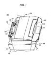
- Fig. 1 is a perspective view which shows an external overall configuration of an ink-jet composite machine which is one of recording apparatuses according to one embodiment of the invention
- Fig. 2 is a perspective view which shows an internal configuration thereof
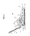
- Fig. 3 is a schematic side view thereof.
- This ink-jet composite machine 100 includes, for example, a printer function to record on single sheets of paper in various sizes from L and A6 sizes to A4 size of JIS standard and post cards, a scanner function to read information written on sheets of paper in sizes up to A4 size of JIS standard and information written on sheets of paper in sizes up to the letter size of US standard and a copying function to make copies on sheets of paper in sizes of JIS standard such as L size, 2L size, B5 size and A4, 8 by 10, and post card.
- a printer function to record on single sheets of paper in various sizes from L and A6 sizes to A4 size of JIS standard and post cards
- a scanner function to read information written on sheets of paper in sizes up to A4 size of JIS standard and information written on sheets of paper in sizes up to the letter size of US standard
- a copying function to make copies on sheets of paper in sizes of JIS standard such as L size, 2L size, B5 size and A4, 8 by 10, and post card.
- this ink-jet composite machine 100 is covered by a housing 101 which is formed substantially into a rectangular parallelepiped as a whole and includes a printer 110 at a lower stage and a scanner 120 at an upper stage thereof. Then, a sheet feeding unit 130 is provided on a rear side of the ink-jet composite machine 100 and a sheet feeding/discharging unit 140 is provided on a front side thereof which includes a power connection/disconnection mechanism which constitutes the invention. Since the user can select one or both of the front mounted sheet feeing unit 130 and the rear mounted sheet feeding/discharging unit 140 as a setting direction for a sheet before recording, the degree of freedom in selecting a setting position of the ink-jet composite machine 100 can be increased. Furthermore, since the sheet is discharged from the sheet feeding/discharging unit 140 mounted on a front side at all times after recording, the user can easily get back the recorded sheet.
- a rectangular flat plate-shaped scanner cover 102 shown in Fig. 1 is provided on an upper surface of the housing 101.
- the scanner cover 102 has a handle 103 formed at a front portion thereof and is mounted on the housing 101 in such a manner as to be rotated about a rotational shaft at a rear portion thereof in directions indicated by arrows a in the figure.
- the scanner 120 since the user can insert the fingers underneath the handle 103 to open and close the scanner cover 102, the egress and ingress of a sheet of paper containing information to be scanned can be facilitated.
- An ink cartridge accommodating portion 104 shown in Fig. 2 where a plurality of ink cartridges 10 are put in and out is formed on each side of a front of the housing 101.
- Each ink cartridge holds therein ink in each color for recording.
- Each cartridge accommodating portion 104 is covered by a transparent or translucent cartridge cover 105 shown in Fig. 1.
- the cartridge cover 105 is mounted in such a manner as to be rotated about a rotational shaft at a lower portion thereof. Since the user can replace ink cartridges 10 by pushing lightly the cartridge cover 105 so as to unlock a locked portion to thereby open the cartridge accommodating portion 104 without lifting up the whole of the heavy scanner 120 as has been done with the conventional counterpart, the working efficiency can be increased.
- a control unit 106 which indicates the operation of each of the printer 110, the scanner 120 and a copier is provided on the upper surface of the housing 101 just in front of the scanner cover 102.
- the control unit 106 includes: buttons, not shown, of a power system for power on/off of the machine, an operation system for paper tip positioning or ink flushing, and a processing system for e.g. image processing; and a liquid crystal panel 107 for indicating the status, and others. The user can operates the buttons and others while looking at the liquid crystal panel 107 for confirmation.
- a rear sheet feeding port 131 is, as shown in Fig. 1, formed in the sheet feeding unit 130 in such a manner as to open upwards in a rectangular shape, and a frame 132 is provided in such a manner as to extend along both end edges and a rear edge of the rear sheet feeding port 131.
- a paper support 133 which supports a single sheet or a plurality of sheets to be fed
- a rear auto sheet feeder hereinafter, referred to as a rear ASF
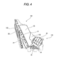
- Fig. 4 is a side view which shows in detail the paper support 133 and the rear ASF 134, and the configuration will be described with reference to Figs. 1 to 4.
- the paper support 133 includes a first support and a second support which support a rear side of a sheet, as well as a stationary edge guide 23 and a movable edge guide 24 which guide both side edges of a sheet.
- the rear ASF 134 includes a hopper 31 which lifts up sheets supported on the paper support 133 for feeding, a sheet feeding roller 32 which takes out sheets which are lifted up by the hopper 31, a retard roller 33 which separates a top sheet of sheets fed by the sheet feeding roller 32 in a superposed state from the other sheets so that only the top sheet can be fed and a sheet returning unit 34 which returns to the hopper 31 the remaining sheets which are separated by the retard roller 33.
- the first support 21 is formed into a flat plate shape and is provided in such a manner as to be freely stowed into and pulled out of an inside of a rear wall of the frame 132
- the second support 22 is formed into a flat plate shape and is provided in such a manner as to be freely stowed into and pulled out of the first support 21. Since the first support 21 and the second support 22 are formed in such a manner as to be freely extended and contracted in a sheet feeding direction, the supports can be stowed compact when not in use, whereas when in use, they can support sheets in various sizes in an ensured fashion.
- the stationary edge guide 23 is formed integrally with the hopper 31 into a shape which follows a right side wall of the frame 132 when viewed from the front of the machine
- the movable edge guide 24 is formed into a shape which follows a left side wall of the frame when viewed from the front of the machine and is mounted on the hopper 31 in such a manner as to move substantially in parallel with the rear wall of the frame 132 between the left side wall and the right side wall thereof. Since the stationary edge guide 23 and the movable edge guide 24 can guide both side edges of sheets in an ensured fashion even in case the sheets are different in size, the feeding of sheets can be implemented with high accuracy.
- the hopper 31 is formed into a flat plate shape so that sheets can be placed thereon and is provided substantially in parallel with the rear wall of the frame 132 such that a lower end is situated in the vicinity of the sheet feeding roller 32 and an upper end thereof is situated close to a top portion of the rear wall of the frame 132.
- a compression spring not shown, which is connected to the rear wall of the frame 132 at one end thereof is connected to a rear side of a lower end of the frame 132 at the other end thereof, whereby the hopper 31 is provided in such a manner as to rotate at the lower end about the upper end thereof by virtue of the extension and contraction of the compression spring.
- the sheet feeding roller 32 is formed into a D-shape by being cut partially circumferentially and is provided in the vicinity of the lower end of the hopper 31 in such a manner as to rotate intermittently so as to friction feed sheets which are lifted up by the hopper 31.
- the retard roller 33 is provided in such a manner as to be brought into abutment with the sheet feeding roller 32 so as to friction separate a top sheet from a sheet thereunder when sheets are fed by the sheet feeding roller 32 in a superposed fashion.
- the rear sheet returning unit 34 is formed into a claw shape and is disposed in the vicinity of the sheet feeding roller 32 so as to catch the remaining sheet separated from the top sheet by the retard roller 33 on a claw formed thereon to thereby return it to the hopper 31.
- a front sheet feeding/discharging port 141 is formed in the sheet feeding/discharging unit 140 in such a manner as to open forwards in a rectangular shape, and a supply sheets tray 142 is provided below the front sheet feeding/discharging port 141, a discharged sheets tray 143 being provided above the supply sheets tray 142.
- a front auto sheet feeder (hereinafter, referred to as a front ASF) 144, which is provided with a mechanism characteristic of the invention in which sheets stocked in the supply sheets tray 142 are automatically fed sheet by sheet, and a front sheet discharging mechanism (hereinafter, referred to as a front EJ) 145 which automatically discharges fed sheets to the discharged sheets tray 143 are provided deep into the front sheet feedingldischarging port 141.
- a front ASF a front auto sheet feeder
- a front EJ front sheet discharging mechanism
- the supply sheets tray 142 is, as shown in Figs. 2 and 3, formed into a flat plate shape, and sheets to be fed for recording are designed to be stacked for stock on an upper surface thereof.
- the discharged sheets tray 143 includes, as shown in Figs. 2 and 3, a first tray 143a, a second tray 143b and a third tray 143c.
- the first tray 143a is formed into a flat plate shape and is provided on a main body frame 108 which resides deep in the sheet feeding/discharging unit 140 in such a manner as to rotate at a rear portion thereof
- the second tray 143b is formed into a flat plate shape and is provided in such a manner as to be freely stowed into and pulled out of the first tray 143a
- the third tray 143c is formed into a flat plate shape and is provided in such a manner as to be freely stowed into and pulled out of the second tray 143b.
- the discharged sheets tray 143 is made such that discharged sheets after recording are stacked in place on an upper surface thereof in such a state that the second tray 143b and the third tray 143c are pulled out. Since the second tray 143b and the third tray 143c are formed in such a manner as to be freely extended and contracted in a sheet discharging direction, the trays can be stowed compact when not in use. In addition, when in use, the trays allow discharged sheets in various sizes to be stacked in place thereon in an ensured fashion. Note that the sheet feeding/discharging unit 140 is also formed such that a tray which stores therein thick sheets that cannot be bent when fed and discharged or optical discs is manually inserted thereinto for feeding.
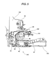
- Fig. 5 is a side view which shows in detail the front ASF 144 which is provided with the mechanism characteristic of the invention, and the description continues by reference to Figs. 3 and 5.
- the front ASF 144 includes a pick-up roller unit 41 which takes out sheets stored in the supply sheets tray 142 and a bank portion 42 which alters the direction of a sheet that is taken out by the pick-up roller unit 41.
- the front ASF 144 includes further a retard roller unit 43 which separates a top sheet of sheets fed by the pick-up roller unit 41 in a superposed state from a sheet thereunder so that only the top sheet can be fed further, a front sheet returning unit 44 which returns to the supply sheets tray 142 the remaining sheets which are so separated by the retard roller unit 43, an intermediate roller 45 which reverses a sheet being fed in a U-shape and an assist roller 46.
- the pick-up roller unit 41 is disposed above a rear portion of the supply sheets tray 142 and is provided in such a manner as to freely swing in vertical directions with respect to the supply sheets tray 142 so as to friction feed sheets stored in the supply sheets tray 142 when lowered.
- the hank portion 42 is provided in such a manner as to be inclined rearwards at the rear portion of the supply sheets tray 142 so as to alter the direction of sheets fed by the pick-up roller unit 41 such that distal ends of the sheets so fed are directed upwards thereat,
- the retard roller unit 43 is provided in such a manner as to be brought into abutment with the intermediate roller 45, whereby when sheets are fed by the pick-up roller unit 41 in a superposed state, a top sheet of the superposed sheets is friction separated from a sheet thereunder so that only the top sheet can be fed further.
- the front sheet returning unit 44 is formed into a claw shape and is provided in the vicinity of the retard roller unit 43 so as to catch the remaining sheets under the top sheet so separated on a claw formed thereon to return them to the supply sheets tray 142.
- the assist roller 46 is provided in such a manner as to be in abutment with the intermediate roller 45 at all times so as to hold the top sheet separated by the retard roller unit 43 between the intermediate roller 45 and itself to thereby reverse the top sheet so held in the U-shape to be fed further to a platen 155.
- the front EJ 145 includes, as shown in Fig 3, a first sheet discharging roller 51 and a first serrated roller 52, and a second sheet discharging roller and a second serrated roller 54.
- the first sheet discharging roller 51 is provided on a downstream side of the platen 155 in a sheet carrying direction so as to hold a sheet that has passed through the platen 155 together with the first serrated roller 52 for discharge
- the second sheet discharging roller 53 is provided downstream of the first sheet discharging roller 51 in the sheet carrying direction so as to hold the sheet discharged by the first sheet discharging roller 51 together with the second serrated roller 54 for discharge on to the discharged sheets tray 143.
- a sheet feeding roller 151 which feeds a sheet in an auxiliary scanning direction in synchronism with a recording operation and a follower roller 152 thereof, a carriage 153 which moves in a main scanning direction in synchronism with a recording operation, a recording head 154 which discharges ink in synchronism with a recording operation and the platen 155 which holds a sheet flat at the time of recording.
- the sheet feeding roller 151 is, as shown in Fig. 3, provided on an upstream side of the platen 155 in the sheet carrying direction and is adapted to feed out by a sheet feeding mechanism 156 shown in Fig. 2 a sheet that is fed by the sheet feeding roller 32 or a sheet that is reversed to be fed by the intermediate roller 45 on to the platen 155 while holding the sheets together with the follower roller 152.
- the carriage 153 is installed on a carriage guide shaft 157 shown in Fig. 3 in such a manner that the carriage guide shaft 157 extends through the carriage 153 above the platen 155 and is connected to a carriage belt 158 shown in Fig. 2 such that, when the carriage belt 158 is activated by a carriage motor 159 shown in Fig. 2, the carriage 153 is entrained by the movement of the carriage belt 158 to thereby reciprocate along the carriage guide shaft 157 while being guided thereby.
- the recording head 154 is, as shown in Fig. 3, installed on the carriage 153 in such a manner as to define a predetermined space with respect to the platen 155 and includes, for example, a black ink recording head which discharges a black ink and a plurality of color ink recording heads which discharge inks in five colors such as yellow, cyan, light cyan, magenta, and light magenta. Then, the recording head 154 has provided therein a pressure generating chamber and a nozzle opening connected to the pressure generating chamber, and ink is reserved in the pressure generating chamber and is pressurized under a predetermined pressure, whereby ink is discharged from the nozzle opening towards a sheet in droplets whose size is controlled.
- the front ASF 144 provided with the mechanism characteristic of the invention will further be described by reference to the drawings.
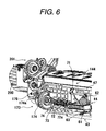
- Fig. 6 is a perspective view of details of a main part of the front ASF 144 as seen from a rear side thereof
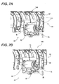
- Fig. 7 shows perspective views of the main part of the front ASF 144 as seen from a front side thereof
- Fig. 8 is a perspective view which shows all elements making up a power transmission path of the front ASF 144 in such a state that the elements are removed therefrom.
- the front ASF 144 includes the retard roller unit 43 which separates a top sheet of sheets fed by the pick-up roller unit 41 in a superposed state from a sheet thereunder so that only the top sheet can be fed further, the front sheet returning unit 44 which returns to the supply sheets tray 142 the remaining sheets which are so separated by the retard roller unit 43, and a clutch mechanism 173 characteristic of the invention which connects and disconnects power to the retard roller unit 43 and the front sheet returning unit 44.
- the retard roller unit 43 includes a retard roller 61 which is brought into abutment with the intermediate roller 45 shown in Fig. 5 so as to separate a top sheet from sheets fed in a superposed state from a sheet thereunder so that only the top sheet so separated can be fed further and a roller holder 62 which supports rotatably the retard roller 61 in such a manner as to bring the retard roller 61 into abutment with and separation from the intermediate roller 45.
- the retard roller 61 is formed into a cylindrical shape and is covered by, for example, rubber around a circumferential surface thereof in order to enhance the friction coefficient.
- the roller holder 62 supports rotatably the retard roller 61 at one end thereof and is supported rotatably on a frame 47 at the other end thereof, whereby the roller holder 62 is made to swing freely about the other end at the one end thereof, that is, the roller holder 62 holds the retard roller 61 in such a manner as to swing freely.
- the retard roller 61 is fixed by the roller holder 62, and the roller holder 62 is locked by a retard roller tension spring 63 which imparts a clockwise tension between the frame 47 and itself at all times.
- the front sheet returning unit 44 includes a sheet return 71 which abuts a distal end of the sheet that is separated from the top sheet under which it resided by the retard roller 61 to push return the sheet, a sheet return shaft 72 which turns the sheet return 71 and swings the retard roller 61, a cam follower 73 shown in Figs. 6 and 8 which transmits a drive force from a PF motor 300 to the sheet return shaft 72 and a cam clutch 74.
- the sheet return 71 is formed into claws which are formed integrally on the sheet return shaft 72 in such a manner as to project therefrom at sides of the retard roller 61.
- the cam follower 73 is formed into an L-shape and is formed integrally on the sheet return shaft 72 in such a manner as to project from one end of the sheet return shaft 72.
- the cam clutch 74 is supported rotatably on the frame 47 and is formed into a shape which allows the cam clutch 74 to be brought into abutment with and separation from the cam follower 73 so as to rotate the sheet return shaft 72 intermittently. It is the clutch mechanism 73, characteristic of the invention, which connects and disconnects power to and from the cam clutch 74.
- This clutch mechanism 173 can change over, as required, the connection and disconnection of power transmitted from the PF motor 300 by means of a trigger lever 176 (a lever).
- the sheet return shaft 72 is supported rotatably on the frame 47.
- the sheet return 71 is situated on the sides of the retard roller 61, in the event that the sheet return shaft 72 is formed into a straight rod shape, the sheet return shaft 72 will interfere with the roller holder 62.
- a portion 72a of the sheet return shaft 72 which interferes with the roller holder 62 is formed into a crank shape so as to avoid the interference with the roller holder 62.
- the sheet return shaft 72 further has a function to turn the sheet return 71 and a function to swing the retard roller 61. Due to this, a retarder cam 75 is, as shown in Fig. 7, formed integrally on the sheet return shaft 72 for turning the roller holder 62, and a retarder cam follower 76 is integrally formed on the roller holder 62 in such a manner as to be brought into abutment with and separation from the retarder cam 75.
- the crank 72a on the sheet return shaft 72 the sheet return 71 and the retarder cam 75 in such a manner as to adjust the phases thereof, the sheet return 71 can be turned without interfering with the roller holder 62 and the retard roller 61 can be swung, when the sheet return shaft 72 is rotated.
- the power transmission path of the front ASF 114 shown in Fig. 8 will be described. Firstly, power generated at the PF motor 300 which constitutes a power supply is transmitted to the sheet feed roller 151 by a transmission belt mechanism 301 of the sheet feeding mechanism 156. Next, the power at the sheet feeding roller 151 is transmitted to the intermediate roller 45 by a composite gear mechanism 302, and the power transmitted to the intermediate roller 45 is then transmitted to a clutch gear 175 via a composite gear mechanism 170.
- the power is connected and disconnected by the clutch mechanism 173.
- the power can be connected and disconnected to and from the sheet return shaft 72 via the cam clutch 74 and the cam follower 73 by bringing the trigger lever (the lever) of the clutch mechanism 173 into contact with a clutch cover projecting portion 174a as required.
- the power connecting and disconnecting trigger lever (the lever) 176 operates when power generated at an ASF motor 200 is transmitted thereto from a composite gear mechanism 201. Then, the power transmitted from the sheet return shaft 72 is transmitted to the retarder cam 75 to thereby put the retard roller 61 and the sheet return 71 into operation.
- the details of the clutch mechanism 173 will be described by reference to the drawings.
- Fig. 9 is a perspective view which shows the details and periphery of the clutch mechanism 173 which is characteristic of the invention
- Figs. 10 to 13 are perspective views of respective constituent elements disassembled from the clutch mechanism 173.
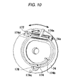
- Fig. 10 is a drawing which shows a state in which a clutch cover and the cam clutch are fixed
- Figs. 11 and 12 are perspective views which show the details of the clutch cover
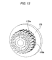
- Fig. 13 is a perspective view which shows the details of a clutch gear.
- the clutch mechanism 173 includes a clutch cover 174 locked on the cam clutch 74, a clutch cover tension spring 177 which locks the clutch cover 174 on the cam clutch 74, the trigger lever (the lever) 176 which changes over the connection and disconnection of power and the clutch cover projecting portion 174a.
- a specific flow of connection and disconnection of power by the clutch mechanism 173 will be described later on by reference to the drawings.
- the clutch cover 174 is provided in parallel with the cam clutch 74 and is locked on the cam clutch 74 rotatably by a clutch cover fixing hole 174c residing at a rotational center of the clutch cover 174 and a clutch cover fixing pin 178.
- the clutch cover tension spring 177 is locked on the clutch cover 174 and the cam clutch 74 at a clutch side compression spring mounting portion 174d and a cam side compression spring mounting portion 74a which are provided on the clutch cover 174 and the cam clutch 74, respectively.
- This clutch cover tension spring 177 imparts a tension in a direction in which the clutch cover 174 and a clutch gear 175, which will be described later on, are brought into mesh engagement with each other.
- the fixing method of the clutch cover 174 other fixing methods than the fixing method using the clutch cover fixing pin 178 can be considered which includes, for example, a method in which a rail member is prepared in a direction which is parallel with a direction in which the clutch is brought into engagement so as to move the clutch cover 174 in parallel.
- This is the method in which the clutch cover 174 is fixed to the rail member and is further surrounded by a circular member around an outer circumference thereof, so that the trigger lever 176 is brought into abutment with and separation from the outer circumferential portion so formed.
- the clutch cover 174 includes the clutch cover projecting portion 174a, a first clutch cover claw portion 174b, the clutch cover fixing hole 174c, the clutch side compression spring mounting portion 174d and a second clutch cover claw portion 174e which is characteristic of the invention.
- the clutch gear 175 includes a first clutch gear toothed portion 175a with which the first clutch cover claw portion 174b is brought into mesh engagement and a second clutch gear toothed portion 175b which is also characteristic of the invention.
- the clutch cover projecting portion 174a is brought into abutment with and separation from the trigger lever (the lever) 176.
- the first clutch cover claw portion 174b is brought into mesh engagement with the clutch gear portion 175a so as to connect and disconnect power.
- the clutch cover fixing pin 178 is inserted into the clutch cover fixing hole 174c.
- the one end of the clutch cover tension spring 177 is locked on the clutch cover joining claw 174d.
- the second clutch cover claw portion 174e which is characteristic of the invention, is formed in parallel with the first clutch cover claw portion 174b.
- the first clutch gear toothed portion 175a is brought into mesh engagement with the first clutch cover claw portion 174b for connection and disconnection of power.
- the second clutch gear toothed portion 175b which is also characteristic of the invention, is formed in parallel with the first clutch gear toothed portion 175a.
- This second clutch gear toothed portion 175b is, as has been described previously, brought into mesh engagement with the second clutch cover claw portion 174e and is formed so as to have a second mesh engagement portion where the second clutch gear toothed portion 175b meshes with the second clutch cover claw portion 174e in an opposite direction to the direction of a first mesh engagement portion at which the first clutch gear toothed portion 175a meshes with the first clutch cover claw portion 175b.
- the first mesh engagement portion between the first clutch cover claw portion 174b and the first clutch gear toothed portion 175a is characterized by a configuration in which power can be transmitted in a forward direction but is disconnected in a reverse or backward direction.
- the second mesh engagement portion between the second clutch cover claw portion 174e and the second clutch gear toothed portion 175b is characterized by a configuration in which power can be transmitted in the reverse or backward direction but is disconnected in the forward direction.
- the clutch mechanism 173 is formed into a two-stage configuration for forward and reverse rotations which connects and disconnects power as required through the operation of the trigger lever (the lever) 176 and the PF motor 300.
- the first clutch cover claw portion 174b is also made into a configuration which facilitates the abutment and separation thereof with and from the first clutch gear toothed portion 175a and is further made to mesh therewith.
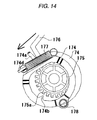
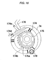
- Figs. 14 to 16 are drawings which describe the operation of the clutch mechanism 173.
- the trigger lever (the lever) 176 is brought into contact with the clutch cover projecting portion 174a which is formed on an outside of the clutch cover 174. Then, this trigger lever (the lever) 176 imparts a force to the clutch cover 174 in a direction in which the clutch cover 174 is disengaged from the clutch gear 175, whereby the clutch cover 174 is separated from the clutch gear 175 to thereby disconnect power.
- This state is regarded as OFF or a standby state.
- the trigger lever (the lever) 176 is dislocated from the clutch cover projecting portion 174a due to a power being imparted thereto from the ASF motor 200. Then, the clutch cover 174 rotates around the clutch cover fixing pin 178 as a fulcrum by a force exerted by the clutch cover tension spring 177, whereby the first clutch cover claw portion 174b is brought into mesh engagement with the first clutch gear toothed portion 175a to thereby transmit power.
- This state is regarded as ON or a driving state.
- the trigger lever (the lever) 176 is brought into contact with the outer circumferential portion of the rotating clutch cover 174 by power from the ASF motor 200. Then, since the clutch cover 174 is rotating, the trigger lever (the lever) 176 is automatically brought into abutment with the clutch cover projecting portion 174a, whereby the clutch cover 174 is pushed by the trigger lever (the lever) 176, so that a force is automatically caused to act in a direction in which the clutch cover 174 is separated from the clutch gear 175 and is then allowed to rotate around the clutch cover fixing pin 178 to thereby be separated from the clutch gear 175.
- Fig. 17 is a view which shows the direction of a force that is generated immediately after the cam follower 73 is brought into abutment with the cam clutch 74
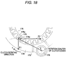
- Fig. 18 is a view which shows the direction of a force that is generated when the clutch cover 174 and the clutch gear 175 are imparted a reaction force shown in Fig. 17 immediately after the clutch cover 174 and the clutch gear 175 are brought into abutment with each other.
- the cam follower 73 is brought into abutment with the cam clutch 74 to thereafter rotate along the cam clutch 74, whereby power can be, as shown in Fig. 9, transmitted to the sheet return shaft 72 which is connected to the cam follower 73.
- a load acting on the retard roller tension spring 63 shown in Fig. 6 is large, and a force generated thereby constitutes a reaction force, which is transmitted to the cam follower 73 via the sheet return shaft 72.
- a reaction force R1 transmitted by the cam follower 73 pushes the cam clutch 74 not in a direction towards a cam center 74b but in a direction as shown in the figure, that is, a direction in which the clutch cover 174 is disengaged from the clutch gear 175 when the cam flower 73 is brought into abutment with the cam clutch 74.
- a force F is generated by the reaction force R1 imparted from the cam follower 73 shown in Fig. 17 at a mesh engagement portion between the clutch cover 174 and the clutch gear 175 when power is attempted to be transmitted in a direction T.
- the user stores a plurality of sheets of paper before recording in the supply sheets tray 142 and then activates the ink-jet composite machine 100.
- the sheets stored in a stacked state in the supply sheets tray 142 are friction fed to the intermediate roller 45 by the pick-up roller unit 41, and only a top sheet of the stacked sheets so fed is separated by the retard roller unit 43 driven by the sheet return shaft 72 so as to be fed further, and the remaining sheets that resided underneath the top sheet so separated are returned to the supply sheets tray 142 by the sheet return 71 driven by the sheet return shaft 72.
- the sheet that is so fed further is held between the sheet feed roller 151 driven by the sheet feeding mechanism 156 and the follower roller 152 thereof to thereby be fed on to the platen 155.
- a control unit of the ink-jet composite machine 100 supplies inks in six colors such as yellow, magenta, light magenta, cyan, light cyan and black from ink cartridges which reserve therein inks in the six colors, respectively, to the recording head 154 and controls discharge timings of the inks in the respective colors and the drive of the carriage 153 and the sheet feeding roller 151 so as to execute highly accurate ink dot control and half-tone processing.
- the sheet on which recording is completed is held by the first sheet discharging roller 51 driven by the sheet feeding mechanism 156 and the associated first serrated roller 52, and the second sheet discharging roller 53 and the associated second serrated roller 54 to thereby be fed to the sheet feeding/discharging unit 140 where the sheet is stacked in place in the discharged sheets tray 143.
- the clutch cover 174 is moved by bringing the trigger lever (the lever) 176 into abutment with and separation from the clutch cover projecting portion 174a, so that the first clutch cover claw portion 174b is brought into engagement with and released from the first clutch gear toothed portion 175a, whereby power is connected and disconnected.
- the two mesh engagement portions of the first mesh engagement portion between the first clutch cover claw portion 174b and the first clutch gear toothed portion 175a and the second mesh engagement portion between the second clutch cover claw portion 174e and the second clutch gear toothed portion 175b can be provided by providing the second clutch cover claw portion 174e and the second clutch cover toothed portion 175b, and as a result, the clutch mechanism 173 can be provided which is formed into the two-stage configuration for the forward and backward rotations.
- the clutch cover 174 is rotatably supported on the cam clutch 74 by means of the clutch cover fixing pin 178 inserted in the clutch cover fixing hole 174c in such a manner as to rotate when the trigger lever (the lever) 176 is brought into abutment with and separation from the clutch cover projecting portion 174a so as to be brought into engagement with and released from the clutch gear 175.
- the first mesh engagement portion between the first clutch cover claw portion 174b and the first clutch gear toothed portion 175a and the second mesh engagement portion between the second clutch cover claw portion 174e and the second clutch gear toothed portion 175b are formed respectively such that a force generated at each of the respective mesh engagement portions is directed towards the rotational center of the clutch cover 174, whereby when a large external force is exerted, even in the event that the clutch cover 174 meshes with the clutch gear 175 at either of the first mesh engagement portion and the second mesh engagement portion, the force exerted is caused to act in the direction in which the clutch cover 174 meshes with the clutch gear 175 so as to prevent the separation of the relevant members at the mesh engagement portion to thereby suppress the jump to a different position on the toothed portion of the gear, thereby making it possible to enhance the power transmission accuracy.
- the invention can be applied to any recording apparatus including, for example, a facsimile transmission device, copying machine and the like, provided that they are provided with a medium feeding apparatus.
- the invention can be applied not only to those recording apparatuses but also to liquid ejecting apparatuses which eject, in place of ink, liquid for a specific application from a liquid ejecting head to a target medium so that the ejected liquid adheres to the target medium.
- the liquid ejecting apparatuses include those equipped with, for example, a color material ejecting head which is used in producing color filters for liquid crystal displays, an electrode material (conductive paste) ejecting head which is used in forming electrodes for organic EL displays and face emitting displays (FED), a biological organic material injecting head which is used in producing biochips and a sample ejecting head as a precision pipette.
- a color material ejecting head which is used in producing color filters for liquid crystal displays
- an electrode material (conductive paste) ejecting head which is used in forming electrodes for organic EL displays and face emitting displays (FED)
- FED face emitting displays
- a biological organic material injecting head which is used in producing biochips
- sample ejecting head as a precision pipette.
Landscapes
- Engineering & Computer Science (AREA)
- Mechanical Engineering (AREA)
- General Engineering & Computer Science (AREA)
- Sheets, Magazines, And Separation Thereof (AREA)
- Ink Jet (AREA)
- Handling Of Sheets (AREA)
- Mechanical Operated Clutches (AREA)
- Accessory Devices And Overall Control Thereof (AREA)
Applications Claiming Priority (2)
| Application Number | Priority Date | Filing Date | Title |
|---|---|---|---|
| JP2004307493 | 2004-10-21 | ||
| JP2005303959A JP4613790B2 (ja) | 2004-10-21 | 2005-10-19 | 動力断続機構及び媒体供給装置と記録装置と液体噴射装置 |
Publications (2)
| Publication Number | Publication Date |
|---|---|
| EP1650041A2 true EP1650041A2 (de) | 2006-04-26 |
| EP1650041A3 EP1650041A3 (de) | 2008-12-03 |
Family
ID=35708729
Family Applications (1)
| Application Number | Title | Priority Date | Filing Date |
|---|---|---|---|
| EP05023012A Withdrawn EP1650041A3 (de) | 2004-10-21 | 2005-10-21 | Abschalt- und Verbind-mechanismus und Aufzeichnungsträgerzuführgerät, Drucker und Flüssichkeitsstrahldrucker |
Country Status (3)
| Country | Link |
|---|---|
| US (1) | US7533984B2 (de) |
| EP (1) | EP1650041A3 (de) |
| JP (1) | JP4613790B2 (de) |
Cited By (1)
| Publication number | Priority date | Publication date | Assignee | Title |
|---|---|---|---|---|
| US9287724B2 (en) | 2010-04-12 | 2016-03-15 | Zih Corp. | Printer mobility and scalability |
Families Citing this family (5)
| Publication number | Priority date | Publication date | Assignee | Title |
|---|---|---|---|---|
| JP4218710B2 (ja) * | 2006-08-03 | 2009-02-04 | セイコーエプソン株式会社 | クラッチ装置、被記録材給送装置、記録装置 |
| JP4218709B2 (ja) * | 2006-08-03 | 2009-02-04 | セイコーエプソン株式会社 | クラッチ装置、被記録材給送装置、記録装置 |
| JP5494149B2 (ja) * | 2010-04-06 | 2014-05-14 | セイコーエプソン株式会社 | 搬送装置 |
| JP6201505B2 (ja) * | 2013-08-12 | 2017-09-27 | セイコーエプソン株式会社 | 媒体処理装置および媒体処理装置の制御方法 |
| JP6607142B2 (ja) * | 2016-05-18 | 2019-11-20 | トヨタ紡織株式会社 | シート駆動装置 |
Family Cites Families (19)
| Publication number | Priority date | Publication date | Assignee | Title |
|---|---|---|---|---|
| US942244A (en) * | 1908-06-15 | 1909-12-07 | Independent Harvester Company | Clutch mechanism. |
| US2090614A (en) * | 1936-03-06 | 1937-08-24 | Ole M Dahl | Speed changing mechanism |
| US2123030A (en) * | 1936-05-20 | 1938-07-05 | New Jersey Machine Corp | Clutch |
| DE685818C (de) | 1937-09-17 | 1939-12-27 | Peddinghaus Paul Ferd Fa | Drehkeilkupplung |
| US3463280A (en) * | 1967-11-01 | 1969-08-26 | Kendale Industries | Pawl-type clutch assembly |
| US3712433A (en) * | 1970-10-07 | 1973-01-23 | Burroughs Corp | Dual torque coupling |
| US4119186A (en) * | 1977-02-28 | 1978-10-10 | Outboard Marine Corporation | Single lever control having a throttle warm-up lever |
| JPS6326434A (ja) * | 1986-07-16 | 1988-02-04 | Canon Inc | 駆動力伝達装置 |
| US5982400A (en) * | 1991-08-22 | 1999-11-09 | Canon Kabushiki Kaisha | Sheet feeding apparatus and image forming system |
| JP3347498B2 (ja) * | 1993-12-30 | 2002-11-20 | キヤノン株式会社 | 記録装置 |
| JPH08326878A (ja) * | 1995-06-05 | 1996-12-10 | Japan Aviation Electron Ind Ltd | アンチバックラッシュ付ギヤ装置 |
| US5838338A (en) * | 1996-05-30 | 1998-11-17 | Hewlett-Packard Company | Adaptive media handling system for printing mechanisms |
| CA2200247C (en) * | 1996-10-29 | 2004-03-16 | Thomas E. Mccue, Jr. | Z-fold print media handling system |
| JP2000203738A (ja) | 1999-01-11 | 2000-07-25 | Canon Inc | シ―ト給送装置及びこの装置を備えた画像形成装置 |
| JP2001063865A (ja) | 1999-08-24 | 2001-03-13 | Canon Inc | シート給送装置および記録装置 |
| JP4688360B2 (ja) | 2001-07-23 | 2011-05-25 | パナソニックシステムネットワークス株式会社 | 給紙装置 |
| KR100442747B1 (ko) * | 2002-03-14 | 2004-08-02 | 주식회사다스 | 자동차용 시트쿠션 펌핑디바이스 |
| JP4058628B2 (ja) * | 2002-03-29 | 2008-03-12 | セイコーエプソン株式会社 | クラッチ装置、給送装置、記録装置 |
| US7306216B2 (en) * | 2002-12-30 | 2007-12-11 | Samsung Electronics Co., Ltd. | Power transmitting apparatus, power switching apparatus, and driving apparatus of multi-function machine using the same |
-
2005
- 2005-10-19 JP JP2005303959A patent/JP4613790B2/ja not_active Expired - Fee Related
- 2005-10-21 EP EP05023012A patent/EP1650041A3/de not_active Withdrawn
- 2005-10-21 US US11/254,772 patent/US7533984B2/en not_active Expired - Fee Related
Cited By (3)
| Publication number | Priority date | Publication date | Assignee | Title |
|---|---|---|---|---|
| US9287724B2 (en) | 2010-04-12 | 2016-03-15 | Zih Corp. | Printer mobility and scalability |
| US9475319B2 (en) | 2010-04-12 | 2016-10-25 | Zih Corp. | Printer mobility and scalability |
| US9895917B2 (en) | 2010-04-12 | 2018-02-20 | Zih Corp. | Printer mobility and scalability |
Also Published As
| Publication number | Publication date |
|---|---|
| JP2006142813A (ja) | 2006-06-08 |
| EP1650041A3 (de) | 2008-12-03 |
| US7533984B2 (en) | 2009-05-19 |
| US20060086203A1 (en) | 2006-04-27 |
| JP4613790B2 (ja) | 2011-01-19 |
Similar Documents
| Publication | Publication Date | Title |
|---|---|---|
| JP2002205855A (ja) | 記録装置 | |
| US7533984B2 (en) | Power connection/disconnection mechanism and medium feeding apparatus, recording apparatus and liquid ejecting apparatus | |
| JP2004330470A (ja) | 液体供給装置及び記録装置 | |
| CN1962382B (zh) | 介质进给装置及液滴喷射装置和记录装置 | |
| CN100391813C (zh) | 供给装置和记录装置 | |
| EP1619150A1 (de) | Zuführvorrichtung und aufzeichnungsvorrichtung | |
| US7497565B2 (en) | Medium feeding device and recording apparatus or liquid ejecting apparatus incorporating the same | |
| JP4419792B2 (ja) | 媒体給送装置 | |
| JP3901639B2 (ja) | 駆動力切換機構及び記録装置 | |
| JP2006117391A (ja) | 媒体給送装置の駆動方法、駆動制御プログラム及び記録装置 | |
| JP4078602B2 (ja) | 補助トレイロック機構及び記録装置 | |
| JP3951751B2 (ja) | 記録装置 | |
| JP2006117389A (ja) | 媒体給送装置の駆動方法、駆動制御プログラム及び記録装置 | |
| JP3897111B2 (ja) | 補助トレイ駆動手段及び記録装置 | |
| JP2005280132A (ja) | 記録装置 | |
| JP4419793B2 (ja) | 媒体給送装置の駆動方法及び記録装置、液体噴射装置 | |
| JP2007131420A (ja) | 媒体供給機構及び液体噴射装置と記録装置 | |
| JP2003267567A (ja) | 記録媒体供給用の駆動力伝達装置及び記録装置 | |
| JP2002302275A (ja) | 記録媒体の供給装置、その組込方法及び記録装置 | |
| JP2005314103A (ja) | 媒体給送装置及び記録装置 | |
| JP2008019057A (ja) | 媒体供給機構及び液体噴射装置と記録装置 | |
| JP2006117387A (ja) | 媒体給送装置及びその媒体給送装置を備えた記録装置と液体噴射装置 | |
| JP2008023838A (ja) | 媒体供給機構及び液体噴射装置と記録装置 | |
| JP2002302280A (ja) | 記録媒体の供給装置及びその供給装置を備えた記録装置 | |
| JP2005280921A (ja) | 媒体給送装置及び記録装置 |
Legal Events
| Date | Code | Title | Description |
|---|---|---|---|
| PUAI | Public reference made under article 153(3) epc to a published international application that has entered the european phase |
Free format text: ORIGINAL CODE: 0009012 |
|
| AK | Designated contracting states |
Kind code of ref document: A2 Designated state(s): AT BE BG CH CY CZ DE DK EE ES FI FR GB GR HU IE IS IT LI LT LU LV MC NL PL PT RO SE SI SK TR |
|
| AX | Request for extension of the european patent |
Extension state: AL BA HR MK YU |
|
| PUAL | Search report despatched |
Free format text: ORIGINAL CODE: 0009013 |
|
| AK | Designated contracting states |
Kind code of ref document: A3 Designated state(s): AT BE BG CH CY CZ DE DK EE ES FI FR GB GR HU IE IS IT LI LT LU LV MC NL PL PT RO SE SI SK TR |
|
| AX | Request for extension of the european patent |
Extension state: AL BA HR MK YU |
|
| RIC1 | Information provided on ipc code assigned before grant |
Ipc: F16D 11/06 20060101ALI20081024BHEP Ipc: B65H 3/56 20060101ALI20081024BHEP Ipc: B41J 29/387 20060101AFI20060208BHEP |
|
| STAA | Information on the status of an ep patent application or granted ep patent |
Free format text: STATUS: THE APPLICATION HAS BEEN WITHDRAWN |
|
| 18W | Application withdrawn |
Effective date: 20090128 |