EP1652982B1 - Machine a tricoter rectiligne, et methode de et dispositif pour produire une programme de tricotage - Google Patents
Machine a tricoter rectiligne, et methode de et dispositif pour produire une programme de tricotage Download PDFInfo
- Publication number
- EP1652982B1 EP1652982B1 EP04747809.4A EP04747809A EP1652982B1 EP 1652982 B1 EP1652982 B1 EP 1652982B1 EP 04747809 A EP04747809 A EP 04747809A EP 1652982 B1 EP1652982 B1 EP 1652982B1
- Authority
- EP
- European Patent Office
- Prior art keywords
- yarn guide
- movable
- yarn
- movable yarn
- accompaniment
- Prior art date
- Legal status (The legal status is an assumption and is not a legal conclusion. Google has not performed a legal analysis and makes no representation as to the accuracy of the status listed.)
- Expired - Lifetime
Links
- 238000009940 knitting Methods 0.000 title claims description 48
- 238000000034 method Methods 0.000 title claims description 9
- 239000000969 carrier Substances 0.000 description 2
- 230000008569 process Effects 0.000 description 2
- 230000008859 change Effects 0.000 description 1
- 230000008878 coupling Effects 0.000 description 1
- 238000010168 coupling process Methods 0.000 description 1
- 238000005859 coupling reaction Methods 0.000 description 1
- 230000003247 decreasing effect Effects 0.000 description 1
- 238000010586 diagram Methods 0.000 description 1
- 239000004744 fabric Substances 0.000 description 1
- 230000004048 modification Effects 0.000 description 1
- 238000012986 modification Methods 0.000 description 1
Images


Classifications
-
- D—TEXTILES; PAPER
- D04—BRAIDING; LACE-MAKING; KNITTING; TRIMMINGS; NON-WOVEN FABRICS
- D04B—KNITTING
- D04B7/00—Flat-bed knitting machines with independently-movable needles
- D04B7/24—Flat-bed knitting machines with independently-movable needles for producing patterned fabrics
- D04B7/26—Flat-bed knitting machines with independently-movable needles for producing patterned fabrics with colour patterns
-
- D—TEXTILES; PAPER
- D04—BRAIDING; LACE-MAKING; KNITTING; TRIMMINGS; NON-WOVEN FABRICS
- D04B—KNITTING
- D04B15/00—Details of, or auxiliary devices incorporated in, weft knitting machines, restricted to machines of this kind
- D04B15/38—Devices for supplying, feeding, or guiding threads to needles
- D04B15/54—Thread guides
- D04B15/56—Thread guides for flat-bed knitting machines
Definitions
- the present invention relates to control of a movable yarn guide in a flat knitting machine, and in particular to a flat knitting machine, a knitting method and an apparatus for generating a knitting program according to the preambles of claims 1, 5 and 8, respectively, and as known from JP 2857840 .
- a movable yarn guide moves along a yarn guide rail, and guides a yarn fed to a yarn carrier.
- the movable yarn guide is required when the needle bed is long.
- the movable yarn guide is provided at a position between an end of the yarn guide rail and the yarn carrier for guiding the yarn supplied from a fixed yarn guide to the yarn carrier at a middle position between the fixed yarn guide and the yarn carrier.
- a pair of left and right movable yarn guides are connected together, and a yarn carrier provided between the movable yarn guides are freely movable without interference with coupling means of the movable yarn guides.
- the yarn carrier contacts the movable yarn guide, the yarn carrier pushes, and moves the movable yarn guide.
- a movable yarn guide accompanies a yarn carrier.
- the movable yarn guides are not always kept at the desired positions. For example, when the yarn carrier pushes the movable yarn guide, the distance between the yarn carrier and one of the movable yarn guides is too small, and the distance between the yarn carrier and the other of the movable yarn guides is too large. Further, until the yarn carrier contacts the movable yarn guide, though the movable yarn guides are positioned at substantially suitable positions, these positions are not always the optimum positions. For example, assuming that the distance between the pair of movable yarn guides is 1/2 of the needle bed length, the distances between the movable yarn guides and the yarn carrier fall within the range of 0 to 1/2 of the needle bed length.
- the range is too wide, and cannot be said as the suitable range.
- Japanese Patent No. 2857840 while the yarn carrier accompanies the movable yarn guide, the distance between the yarn carrier and the movable yarn guide is too small. Therefore, it is not possible to accompany the movable yarn guide with the yarn carrier, and perform knitting at the same time. Thus, it is necessary to move the yarn carrier and the carriage only for accompanying the movable yarn guide with the yarn carrier.
- An object of the present invention is to provide a flat knitting machine, and a method of and apparatus for generating the knitting program in which it is possible to simply place a movable yarn guide at a suitable position relative to a yarn carrier.
- Another object of the present invention is to make it possible to change the position of a movable yarn guide while knitting using a yarn carrier, and maintaining the minimum distance between the yarn carrier and the movable yarn guide.
- a still another object of the present invention is to minimize the movement of a carriage for providing a movable yarn guide at a suitable position.
- a flat knitting machine comprises a yarn carrier and a movable yarn guide provided along a yarn guide rail, and a carriage having accompanying means.
- the accompanying means is capable of allowing accompaniment of the yarn carrier, and releasing the accompaniment of the yarn carrier, and also capable of allowing accompaniment of the movable yarn guide, and releasing the accompaniment of the movable yarn guide.
- Control data for the movable yarn guide is provided in a knitting program to control the carriage such that the position of the movable yarn guide is kept within a predetermined range relative to the yarn carrier for allowing the accompaniment of the movable yarn guide by the accompanying means.
- the control data for the movable yarn guide may be generated or memorized in advance, before starting knitting. Alternatively, the control data for the movable yarn guide may be generated instantly based on control data for the yarn carrier or the like.
- the carriage has a plurality of cam systems for operating a needle on a needle bed and a plurality of the accompanying means along a longitudinal direction of the needle bed, and one of the accompanying means along the longitudinal direction of the needle bed accompanies the yarn carrier, and at the same time, another accompanying means accompanies the movable yarn guide.
- the accompanying means is used for moving both of the yarn carrier and the movable yarn guide.
- Accompanying means for the accompaniment of the movable yarn guide may be provided at opposite ends of the yarn guide rail of the carriage or the like, in addition to the accompanying means for the yarn carrier.
- the position of releasing the accompaniment of the movable yarn guide is selected such that the carriage does not move only for allowing the accompaniment of the movable yarn guide.
- the flat knitting machine is further provided with means for converting control data for the yarn carrier in the knitting program into the control data for the movable yarn guide.
- a method of generating a knitting program for use in a flat knitting machine for operating a needle of a needle bed by a carriage and accompanying a yarn carrier provided in a yarn guide rail by the carriage comprises the yarn carrier and a movable yarn guide provided along the yarn guide rail, and the carriage having accompanying means.
- the accompanying means is capable of allowing accompaniment of the movable yarn guide, and releasing the accompaniment of the movable yarn guide.
- Control data for the yarn carrier is provided in the knitting program.
- the control data for the yarn carrier is converted to generate control data for the movable yarn guide for allowing the position of the movable yarn guide to be kept within a predetermined range relative to the yarn carrier.
- the carriage accompanies the movable yarn guide in accordance with the control data for the movable yarn guide in the knitting program. Therefore, the position of the yarn carrier is controlled finely, and the yarn carrier is always kept at a suitable position relative to the yarn carrier. In the structure, it is possible to smoothly feed the yarn to the yarn carrier. Unlike the structure in which the yarn carrier pushes the movable yarn guide to move the movable yarn guide, the suitable distance between the yarn carrier and the movable yarn guide is maintained even during the movement of the movable yarn guide.
- the carriage is provided with a plurality of accompanying means along the longitudinal direction of the needle bed, when one of the accompanying means accompanies the yarn carrier, and the other of the accompanying means accompanies the movable yarn guide, an interval corresponding to the accompanying means is formed between the yarn carrier and the movable yarn guide.
- the interval roughly corresponds to the interval between the cam systems for operating the needle bed.
- control data for the movable yarn guide may be generated by a knit design apparatus.
- control data for the movable yarn guide may be generated by the flat knitting machine. Since the control data for the yarn carrier is included in the knitting program conventionally, based on the control data for the yarn carrier, it is possible to generate the control data for the movable yarn guide simply.
- control data for the movable yarn guide based on the control data for the yarn carrier by the flat knitting machine, using the knitting program which does not include any control data for the movable yarn guide, it is possible to control the movable yarn guide while knitting.
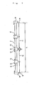
- a reference numeral 2 denotes a yarn guide rail of a flat knitting machine.
- the yarn guide rail 2 supports a yarn carrier 4 and movable yarn guides 6 for feeding yarns 10, 11 to needles on needle beds such that the yarn carrier 4 and the movable yarn guides 6 are freely movable.
- Fixed yarn guides 9 are provided at rail ends 8.
- the movable yarn guides 6 guide the yarns between the fixed yarn guides 9 and the yarn carrier 4.
- each of the movable yarn guides 6 is at substantially the central position between the yarn carrier 4 and the fixed yarn guide 9.
- the position of the movable yarn guide 6 is not limited to exactly the central position between the yarn carrier 4 and the fixed yarn guide 9, and may be deviated from the central position between the yarn carrier 4 and the fixed yarn guide 9.
- the movable yarn guides 6 are controlled based on the assumption that the distance between the movable yarn guides and the yarn carrier is within a predetermined range, and the pair of left and right movable yarn guides do not move beyond the central position of the yarn guide rail.
- the pair of movable yarn guides 6 are provided on both left and right sides of the yarn carrier 4. If the yarn guide rail 2 is sufficiently long, a plurality of movable yarn guides 6 may be provided on each of the left and right sides.
- the movable yarn guide 6 may be provided only on one of the left and right sides.
- L in FIG. 1 denotes the length of the yarn guide rail 2 which is the same as the length of the needle bed, and equal to the maximum stroke of the carriage in the flat knitting machine.
- the yarns may be fed to the yarn carrier 4 from both of the left and right sides, and may be fed from only one of the left and right sides.
- a pair of projections 12, 13 are provided at each of the yarn carrier 4 and the movable yarn guides 6 so that the movable yarn guides 6 may be accompanied the yarn carrier 4 by accompaniment pins of the carriage.
- a pair of yarn holes 14, 15 are provided under the movable guide 6.
- the projection 12 is provided for left movement in FIG 1
- the projection 13 is provided for right movement.
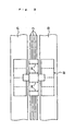
- reference numerals 20 and 21 denote a pair of front and back needle beds.
- a carriage 22 moves back and forth on the needle beds 20, 21 to operate needles on the needle beds.
- the carriage 22 is provided with four cam systems for operating the needles on the needle beds.
- the cam systems are arranged in series in the longitudinal direction of the needle beds 20, 21.
- Four sets of accompanying units 24 for allowing the accompaniment of the yarn carrier 4 and the movable yarn guides 6 and releasing the accompaniment of the yarn carrier 4 and the movable yarn guides 6 are provided for the respective cam systems. That is, the joint movement units 24 accompany the yarn carrier 4 and the movable yarn guides 6 to the right side or the left side.
- the length L of the needle beds 20, 21 is 203,2 cm (80 inches) and for example, the cam systems of the carriage 22 are provided at intervals of 15,24 cm (6 inches). Therefore, the joint movement units 24 are also provided at intervals of 15,24 cm (6 inches).
- the carriage 22 has four cam systems.
- the carriage 22 may have two cam systems or three cam systems.
- two carriages moving on the needle beds are provided separately on the left side and on the right side, one or two cam systems are provided for each of the carriages, and the number of the joint movement units 24 corresponds to the number of the cam systems.
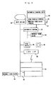
- FIG. 4 shows the relationship between generation of a knitting program and the flat knitting machine.
- a knit design apparatus 30 performs a design for knitting.
- An automatic control data generation unit 32 converts the designed data for knitting to automatic control data (knitting data) for performing knitting by driving the flat knitting machine 42.
- the automatic control data 34 includes data of the movement stroke of the carriage, and data for controlling the needle such as needle selection, knit, tuck, miss, and transfer, yarn carrier control data 36 for controlling the yarn carrier, and other various items of data required for knitting a knitted fabric.
- a movable yarn guide control data generation unit 33 generates movable yarn guide control data 37 based on the yarn carrier control data 36 to control the movable yarn guide on the same yarn path as the yarn carrier to be positioned within a predetermined range from the yarn carrier, and adds the movable yarn guide control data 37 to the automatic control data.
- the automatic control data is sent to the flat knitting machine 42 from a disk drive 38 to the flat knitting machine 42 through a suitable disk 39 such as a CD-ROM or a flexible disk, or through a LAN interface 40.
- a reference numeral 44 denotes a control unit for the flat knitting machine.
- the control unit 44 operates the carriage or the like in accordance with the automatic control data.
- a similar movable yarn guide control data generation unit 45 may be provided for the control unit 44 of the flat knitting machine 42.
- the yarn guide control data generation unit 45 generates control data for the movable yarn guide based on the automatic control data which does not include any control data for the movable yarn guide.
- the control data for the movable yarn guide is generated based on the control data for the yarn carrier to control the movable yarn guide to be positioned within a predetermined range from the yarn carrier.
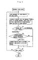
- FIG. 5 shows an example of a generated algorithm for the movable yarn guide. It is assumed that the control data for the yarn carrier has already been generated.
- the control data (movement range) for the yarn carrier is read for one course.
- the control data for the movable yarn guide is generated to control the movable yarn guide to be positioned within a predetermined range with respect to the yarn carrier (step 2). Suitable values for the interval between the yarn carrier and the movable yarn guide are determined. For example, the minimum interval between the yarn carrier and the movable yarn guide is 15,24 cm (6 inches), and the maximum interval between the yarn carrier and the movable yarn guide is 50,8 cm (20 inches).
- the movable yarn guide should be at substantially the central position between the fixed yarn guide and the yarn carrier. It is not absolutely necessary to observe this final rule. For example, it may not be necessary that the movable yarn guide is arranged at substantially the central position between the yarn carrier and the fixed yarn guide if such arrangement increases the stroke of the carriage. In the embodiment, there is a constraint that the movable yarn guide on the left side does not enter the right half of the yarn guide rail, and the movable yarn guide on the right side does not enter the left half of the yarn guide rail.
- step 3 it is determined whether it is possible to accompany the movable yarn guide. If the accompaniment is not possible, a course which allows preliminary movement of the movable yarn guide to a position where the accompaniment can be started is searched, among the preceding courses (step 4).
- step 5 it is checked whether the movement of the yarn is in the final course or not.
- step 6 it is checked whether the movement of the yarn is in the final course or not.
- the algorithm of FIG. 5 is processed for the control data for the respective yarn carriers.
- a problem in the control of the movable yarn guide is that if the position of releasing the accompaniment of the movable yarn guide is not suitable, at the time of starting the next accompaniment, the carriage needs to move only for allowing the accompaniment of the movable yarn guide.
- steps 1, 2, and 6 of FIG. 6 are identical to steps 1, 2, and 6 of FIG. 5 .
- step 11 each time the control data for the movable yarn guide for one course is generated, in step 11, for example, it is determined whether the end of the stroke of the carriage, i.e., the position where the stroke is finished protrudes beyond the end of the subsequent stroke or not.
- the end of the stroke of the carriage protrudes beyond the end of the subsequent stroke
- the accompaniment of the movable yarn guide is released at a position near the end of the stroke, it may not be possible to start the next accompaniment of the movable yarn guide. Therefore, in the case where the end of the stroke of the carriage protrudes beyond the end of the subsequent stroke, at the accompaniment release position temporarily determined in step 2 as described above, it is determined whether the next accompaniment of the movable yarn guide can be started or not (step 12). If there is any problem for starting the accompaniment, in the next course returning from the end of the stroke, the control data for the movable yarn guide is modified to control the movable yarn guide to return toward the center of the knitting width (step 13).
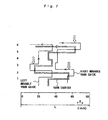
- FIG. 7 shows an example of movement strokes of left and right movable yarn guides.
- the central trajectory represents a trajectory of the yarn carrier.
- the lengths of the needle beds and the yarn guide rail are 203,2 cm (80 inches).
- Yarns are fed from the left and right yarn guides to the yarn carrier.
- the interval between the yarn carrier and the movable yarn guide is in the range of 15,24 to 50,8 cm (6 to 20 inches).
- the left and right movable yarn guides do not move beyond the center of the yarn guide rail.
- the carrier has four systems, and the accompanying unit corresponding to the system at the right end is used for accompanying the right movable yarn guide.
- the system at the second position from the right end is used for accompanying the yarn carrier.
- the system at the left end is used for controlling the left movable yarn guide.
- the accompaniment of the right movable yarn guide is started at a position spaced 15,24 cm (6 inches) from the yarn carrier to the right side
- the accompaniment of the left movable yarn guide is started at a position spaced 12 inches from the yarn carrier to the left side.
- the left movable yarn guide is accompanied, and the accompaniment is released at a suitable position.
- the accompaniment of the right movable yarn guide is started immediately before the end position of the course 1. In this case, at the position near the end position of the course 1, the interval between the left movable yarn guide and the yarn carrier becomes about 50,8 cm (20 inches).
- the right movable yarn guide is accompanied. From a middle position, the left movable yarn guide is also accompanied. The end position of the course 2 protrudes to the left side. Therefore, in the course 3, the left movable yarn guide is accompanied, and the accompaniment is released where the left accompaniment of the movable yarn guide becomes possible in the course 5.
- the right movable yarn guide moves slightly to the right side such that the minimum interval between the right movable yarn guide and the yarn carrier becomes 15,24 cm (6 inches).
- the left movable yarn guide is accompanied, and then, the right movable yarn guide is accompanied. Since the right end of the course 5 protrudes to the right side, in the course 6, the right movable yarn guide is accompanied so that the next accompaniment will not be inhibited.
- Outlined arrows in FIG. 7 indicate portions where the accompaniment of the movable yarn guide in the subsequent courses is taken into account. Assuming that the portions indicated by the outlined arrows are not provided, for example, if the left movable yarn guide is released at a position spaced about 25,4 cm (10 inches) from the left end of the yarn guide rail in the course 2, the accompaniment of the left movable yarn guide is not possible in the course 5. The accompaniment or the like of the right movable yarn guide in the course 6 is performed in the same fashion as in the case of the course 5.
- the movable yarn guide is always kept at a suitable position relative to the yarn carrier. Further, the movement of the carriage only for moving the movable yarn guide is not required. Moreover, since the control data for the movable yarn guide is generated based on the control data for the yarn guide, even in the case where the knitting program does not have any control data for the movable yarn guide, the control data for the movable yarn guide can be generated, and the knitting program can be executed on the flat knitting machine using the control data for the movable yarn guide.
Landscapes
- Engineering & Computer Science (AREA)
- Textile Engineering (AREA)
- Knitting Machines (AREA)
Claims (10)
- Machine à tricoter à plat (42), comportant un chariot (22) prévu selon une direction longitudinale d'une fonture (20, 21), une pluralité de systèmes de cames actionnant une aiguille dans la fonture (20, 21), et une pluralité de moyens d'accompagnement pour permettre l'accompagnement d'un porteur de fil (4) et la libération de l'accompagnement du porteur de fil (4), dans laquelle un fil (10, 11) peut être fourni au porteur de fil (4) à partir d'un guide de fil fixe (9) par l'intermédiaire d'un guide de fil mobile (6), le guide de fil fixe (9) étant prévu au niveau d'une extrémité de la fonture (20, 21), le guide de fil mobile (6) étant positionné entre le guide de fil fixe (9) et le porteur de fil (4), et le porteur de fil (4) et le guide de fil mobile (6) étant prévus sur le même rail de guidage de fil (2), caractérisé en ce que
des premiers moyens d'accompagnement, parmi la pluralité de moyens d'accompagnement, accompagnent le porteur de fil (4) ;
le guide de fil mobile (6) est agencé de telle sorte que le guide de fil mobile (6) peut être accompagné par la pluralité de moyens d'accompagnement et que l'accompagnement du guide de fil mobile (6) peut être libéré par la pluralité des moyens d'accompagnement, et que des deuxièmes moyens d'accompagnement, parmi la pluralité de moyens d'accompagnement, accompagnent le guide de fil mobile (6) et libèrent l'accompagnement du guide de fil mobile (6) ; et
les deuxièmes moyens d'accompagnement sont contrôlés par des données de commande (37) pour le guide de fil mobile (6) dans un programme de tricotage pour contrôler le chariot (22) de telle sorte que l'intervalle entre le guide de fil mobile (6) et le porteur de fil (4) soit maintenu dans une plage prédéterminée, et que la position de libération de l'accompagnement du guide de fil mobile (6) se trouve dans une course des deuxièmes moyens d'accompagnement au moment de l'accompagnement suivant du guide de fil mobile (6). - Machine à tricoter à plat (42) selon la revendication 1, dans laquelle une paire de guides de fil fixes (9) est prévue au niveau des deux extrémités de la fonture (20, 21) et une paire de guides de fil mobiles (6) est prévue au niveau du côté gauche de la fonture (20, 21) et au niveau du côté droit de la fonture (20, 21), et dans laquelle, par les données de commande (37) pour les guides de fil mobiles (6), les guides de fil mobiles (6) ne sont pas accompagnés au-delà du centre de la fonture (20, 21).
- Machine à tricoter à plat (42) selon la revendication 2, dans laquelle on détermine si la fin de la course du chariot dépasse l'extrémité de la course suivante, au niveau de la position de libération d'accompagnement ;
si la fin de la course dépasse, alors on détermine si l'accompagnement suivant des guides de fil mobiles peut être démarré ou pas ; et
si l'accompagnement suivant ne peut pas être démarré, les données de commande (31) pour les guides de fil mobiles sont modifiées de telle sorte que dans le retour de la course suivante à partir de l'extrémité de la course, le guide de fil mobile qui ne peut pas être accompagné est renvoyé en direction du centre de la largeur de tricotage. - Machine à tricoter à plat (42) selon la revendication 1, comprenant en outre des moyens pour convertir des données de commande (36) pour le porteur de fil (4) se trouvant dans le programme de tricotage en données de commande (37) pour le guide de fil mobile (6).
- Procédé de tricotage à l'aide d'une machine à tricoter à plat (42) comportant un chariot (22) prévu selon une direction longitudinale d'une fonture (20, 21), une pluralité de systèmes de cames actionnant une aiguille dans la fonture (20, 21), et une pluralité de moyens d'accompagnement pour permettre l'accompagnement d'un porteur de fil (4) et la libération de l'accompagnement du porteur de fil (4), dans lequel un fil (10, 11) est fourni au porteur de fil (4) à partir d'un guide de fil fixe (9) par l'intermédiaire d'un guide de fil mobile (6), le guide de fil fixe (9) étant prévu au niveau d'une extrémité de la fonture (20, 21), le guide de fil mobile (6) étant positionné entre le guide de fil fixe (9) et le porteur de fil (4), et le porteur de fil (4) et le guide de fil mobile (6) étant prévus sur le même rail de guidage de fil (2), caractérisé en ce que
des premiers moyens d'accompagnement, parmi la pluralité de moyens d'accompagnement, accompagnent le porteur de fil (4) ;
le guide de fil mobile (6) est agencé de telle sorte que le guide de fil mobile (6) peut être accompagné par la pluralité de moyens d'accompagnement et que l'accompagnement du guide de fil mobile (6) peut être libéré par la pluralité des moyens d'accompagnement, et que des deuxièmes moyens d'accompagnement, parmi la pluralité de moyens d'accompagnement, accompagnent le guide de fil mobile (6) et libèrent l'accompagnement du guide de fil mobile (6) ; et
les deuxièmes moyens d'accompagnement sont contrôlés par des données de commande (37) pour le guide de fil mobile (6) dans un programme de tricotage pour contrôler le chariot (22) de telle sorte que l'intervalle entre le guide de fil mobile (6) et le porteur de fil (4) soit maintenu dans une plage prédéterminée, et que la position de libération de l'accompagnement du guide de fil mobile (6) se trouve dans une course des deuxièmes moyens d'accompagnement au moment de l'accompagnement suivant du guide de fil mobile (6). - Procédé de tricotage selon la revendication 5, dans lequel une paire de guides de fil fixes (9) est prévue au niveau des deux extrémités de la fonture (20, 21) et une paire de guides de fil mobiles (6) est prévue au niveau du côté gauche de la fonture (20, 21) et au niveau du côté droit de la fonture (20, 21), et dans lequel, par les données de commande (37) pour les guides de fil mobiles (6), les guides de fil mobiles (6) ne sont pas accompagnés au-delà du centre de la fonture (20, 21).
- Procédé de tricotage selon la revendication 6, dans lequel on détermine si la fin de la course du chariot dépasse l'extrémité de la course suivante, au niveau de la position de libération d'accompagnement ;
si la fin de la course dépasse, alors on détermine si l'accompagnement suivant des guides de fil mobiles peut être démarré ou pas ; et
si l'accompagnement suivant ne peut pas être démarré, les données de commande (31) pour les guides de fil mobiles sont modifiées de telle sorte que, dans le retour de la course suivante à partir de la fin de la course, le guide de fils mobile qui ne peut pas être accompagné est renvoyé en direction du centre de la largeur de tricotage. - Appareil pour générer un programme de tricotage pour une machine à tricoter à plat (42) selon la revendication 1, caractérisé en ce que
des données de commande (37) pour le guide de fil mobile (6) sont générées de telle sorte qu'un intervalle entre le guide de fil mobile (6) et le porteur de fil (4) est maintenu dans une plage prédéterminée, et la position de libération de l'accompagnement du guide de fil mobile (6) se trouve dans une course des deuxièmes moyens d'accompagnement au moment de l'accompagnement suivant du guide de fil mobile (6) en contrôlant les deuxièmes moyens d'accompagnement. - Appareil de génération de programme de tricotage selon la revendication 8, dans lequel une paire de guides de fil fixes (9) est prévue au niveau des deux extrémités de la fonture (20, 21) et une paire de guides de fil mobiles (6) est prévue au niveau du côté gauche de la fonture (20, 21) et au niveau du côté droit de la fonture (20, 21), et dans lequel, par les données de commande (37) pour les guides de fil mobiles (6), les guides de fil mobiles (6) ne sont pas accompagnés au-delà du centre de la fonture (20, 21).
- Appareil de génération de programme de tricotage selon la revendication 9, dans lequel on détermine si la fin de la course du chariot dépasse l'extrémité de la course suivante, au niveau de la position de libération d'accompagnement ;
si la fin de la course dépasse, alors on détermine si l'accompagnement suivant des guides de fil mobiles peut être démarré ou pas ; et
si l'accompagnement suivant ne peut pas être démarré, les données de commande (31) pour les guides de fil mobiles sont modifiées de telle sorte que dans le retour de la course suivante à partir de l'extrémité de la course, le guide de fil mobile qui ne peut pas être accompagné est renvoyé en direction du centre de la largeur de tricotage.
Applications Claiming Priority (2)
| Application Number | Priority Date | Filing Date | Title |
|---|---|---|---|
| JP2003289782A JP2005060857A (ja) | 2003-08-08 | 2003-08-08 | 横編機、編成プログラム、及び編成プログラムの生成方法 |
| PCT/JP2004/010398 WO2005014904A1 (fr) | 2003-08-08 | 2004-07-22 | Machine a tricoter a mailles cueillies |
Publications (3)
| Publication Number | Publication Date |
|---|---|
| EP1652982A1 EP1652982A1 (fr) | 2006-05-03 |
| EP1652982A4 EP1652982A4 (fr) | 2007-08-29 |
| EP1652982B1 true EP1652982B1 (fr) | 2014-10-08 |
Family
ID=34131563
Family Applications (1)
| Application Number | Title | Priority Date | Filing Date |
|---|---|---|---|
| EP04747809.4A Expired - Lifetime EP1652982B1 (fr) | 2003-08-08 | 2004-07-22 | Machine a tricoter rectiligne, et methode de et dispositif pour produire une programme de tricotage |
Country Status (6)
| Country | Link |
|---|---|
| US (1) | US7474936B2 (fr) |
| EP (1) | EP1652982B1 (fr) |
| JP (1) | JP2005060857A (fr) |
| KR (1) | KR101081915B1 (fr) |
| CN (1) | CN100503927C (fr) |
| WO (1) | WO2005014904A1 (fr) |
Families Citing this family (8)
| Publication number | Priority date | Publication date | Assignee | Title |
|---|---|---|---|---|
| US7860604B2 (en) * | 2006-06-27 | 2010-12-28 | Quiq, Llc | Method for controlling access to and segregating dispensed items |
| CN101796234B (zh) * | 2007-09-07 | 2011-07-13 | 株式会社岛精机制作所 | 横机及其给纱方法 |
| FR2994444B1 (fr) * | 2012-08-08 | 2015-05-01 | Interstyl Les Ateliers De Boissiers | Procede de tricotage de tapisseries et tapisseries fabriquees par ce procede |
| EP2813608B1 (fr) * | 2013-06-11 | 2016-07-13 | H. Stoll AG & Co. KG | Machine à tricoter rectiligne |
| JP6465742B2 (ja) * | 2015-05-12 | 2019-02-06 | 株式会社島精機製作所 | 移動糸ガイドを備える横編機 |
| EP3309282B1 (fr) * | 2016-10-14 | 2022-02-09 | KARL MAYER STOLL R&D GmbH | Tricoteuse rectiligne destinée à poser des fils de trame |
| EP3803643A1 (fr) | 2018-05-30 | 2021-04-14 | NIKE Innovate C.V. | Systèmes et procédés de production d'un vêtement |
| CN114411322A (zh) * | 2022-02-15 | 2022-04-29 | 苏州捷蓝智能设备有限公司 | 一种横机用恒速导纱系统 |
Citations (1)
| Publication number | Priority date | Publication date | Assignee | Title |
|---|---|---|---|---|
| EP0718427A1 (fr) * | 1994-12-22 | 1996-06-26 | Shima Seiki Manufacturing, Ltd. | Métier à tricoter rectilique |
Family Cites Families (12)
| Publication number | Priority date | Publication date | Assignee | Title |
|---|---|---|---|---|
| BE759655A (fr) | 1969-12-01 | 1971-04-30 | Courtaulds Ltd | Machine a tricoter rectiligne |
| JPS5421464B2 (fr) * | 1974-06-21 | 1979-07-31 | ||
| IT1037710B (it) * | 1975-04-29 | 1979-11-20 | Zamark Srl | Dispositivo guidafili per macchine rettilinee da maglieria |
| JPS58126351A (ja) * | 1982-01-22 | 1983-07-27 | 株式会社島精機製作所 | 横編機における糸案内装置 |
| JP2903152B2 (ja) * | 1997-04-15 | 1999-06-07 | 株式会社島精機製作所 | 横編機の糸供給機構 |
| DE19936067A1 (de) * | 1999-07-30 | 2001-02-01 | Stoll & Co H | Flachstrickmaschine mit mindestens einem Nadelbett |
| DE60225255T2 (de) * | 2001-03-30 | 2009-03-19 | Shima Seiki Manufacturing Ltd. | Fadenführer für strick- oder kulierwirkmaschine |
| WO2003010378A1 (fr) * | 2001-07-24 | 2003-02-06 | Shima Seiki Mfg., Ltd. | Dispositif d'alimentation de fil d'un metier trame et procede d'alimentation de fil destine a un tel metier |
| JP4016012B2 (ja) * | 2003-10-10 | 2007-12-05 | 株式会社島精機製作所 | 横編機用摺動抵抗付加装置 |
| JP4163085B2 (ja) * | 2003-10-10 | 2008-10-08 | 株式会社島精機製作所 | 移動体連行状態切換え可能な横編機 |
| CA2779372C (fr) * | 2009-11-20 | 2014-12-30 | Android Industries Llc | Appareil gonfleur, systeme et procede d'utilisation de ce dispositif |
| JP6250589B2 (ja) * | 2015-05-13 | 2017-12-20 | 三菱電機ビルテクノサービス株式会社 | 空調システム |
-
2003
- 2003-08-08 JP JP2003289782A patent/JP2005060857A/ja active Pending
-
2004
- 2004-07-22 WO PCT/JP2004/010398 patent/WO2005014904A1/fr not_active Ceased
- 2004-07-22 EP EP04747809.4A patent/EP1652982B1/fr not_active Expired - Lifetime
- 2004-07-22 CN CNB2004800227490A patent/CN100503927C/zh not_active Expired - Fee Related
- 2004-07-22 US US10/567,105 patent/US7474936B2/en not_active Expired - Fee Related
- 2004-07-22 KR KR1020067001037A patent/KR101081915B1/ko not_active Expired - Fee Related
Patent Citations (1)
| Publication number | Priority date | Publication date | Assignee | Title |
|---|---|---|---|---|
| EP0718427A1 (fr) * | 1994-12-22 | 1996-06-26 | Shima Seiki Manufacturing, Ltd. | Métier à tricoter rectilique |
Also Published As
| Publication number | Publication date |
|---|---|
| JP2005060857A (ja) | 2005-03-10 |
| KR20060039912A (ko) | 2006-05-09 |
| US20080168802A1 (en) | 2008-07-17 |
| EP1652982A4 (fr) | 2007-08-29 |
| CN100503927C (zh) | 2009-06-24 |
| KR101081915B1 (ko) | 2011-11-09 |
| EP1652982A1 (fr) | 2006-05-03 |
| CN1833061A (zh) | 2006-09-13 |
| US7474936B2 (en) | 2009-01-06 |
| WO2005014904A1 (fr) | 2005-02-17 |
Similar Documents
| Publication | Publication Date | Title |
|---|---|---|
| EP1652982B1 (fr) | Machine a tricoter rectiligne, et methode de et dispositif pour produire une programme de tricotage | |
| EP3315642B1 (fr) | Procédé de tricotage par vanisage et machine à tricoter rectiligne pour le procédé | |
| US7269975B2 (en) | Cam apparatus for knitting fabric | |
| US6857294B2 (en) | Method for knitting intarsia pattern knitting fabric and knitting program producing device therefor | |
| EP1462555B1 (fr) | Procede de tricotage de motif intersia | |
| EP2025785B1 (fr) | Procede de tricotage de tissu a motifs intarsia et metier a mailles cueillies | |
| EP1717362B1 (fr) | Procede de tricotage et tricot pour un motif intersia, dispositif de conception de tricot | |
| US5758518A (en) | Method of forming transit yarn fastening portion | |
| EP0470789A2 (fr) | Procédé pour tricoter un vêtement au moyen d'un nombre de chariots | |
| US5819558A (en) | Method of lowering the yarn height for knitting single knit fabric | |
| EP2568068A1 (fr) | Procédé pour le tricotage dans une tricoteuse rectiligne et appareil d'édition de données pour le tricotage | |
| EP1514963B1 (fr) | Metier a mailles cueillies presentant un dispositif de platine d'abattage mobile | |
| JP2005060857A5 (fr) | ||
| WO2009116419A1 (fr) | Métier à mailles cueillies et procédé de tricotage utilisant le chevalement du métier à mailles cueillies | |
| EP1959041B1 (fr) | Procede et dispositif de coupe/maintien de chaine dans un metier a mailles cueillies | |
| EP2441868B1 (fr) | Dispositif d'alimentation en fil et procédé d'alimentation en fil pour machine à tricoter | |
| EP1652981B1 (fr) | Unitè a platines pour machine de tricotage trame | |
| EP1908868B1 (fr) | Metier a mailles cueillies avec presseur a point et procede de controle correspondant | |
| EP1972709A1 (fr) | Procede et dispositif de coupe/maintien de chaine dans un metier a mailles cueillies | |
| US6668595B2 (en) | Weft knitting machine with transfer mechanism | |
| EP1505185B1 (fr) | Metier a mailles cueillies equipée de platine de report et procede de report de mailles utilisant platine de report | |
| EP0604164B1 (fr) | Procédé pour le tricotage d'un dessin à croisement et dispositif pour le tricotage d'un dessin à croisement à un métier à tricoter rectiligne | |
| JPH03167350A (ja) | 編機 | |
| JPH093753A (ja) | 横編機におけるヤーンフィーダ | |
| JP2006265794A (ja) | 横編機によるタックコースを含む編地の編成方法とそのプログラム、及びデザイン装置 |
Legal Events
| Date | Code | Title | Description |
|---|---|---|---|
| PUAI | Public reference made under article 153(3) epc to a published international application that has entered the european phase |
Free format text: ORIGINAL CODE: 0009012 |
|
| 17P | Request for examination filed |
Effective date: 20060208 |
|
| AK | Designated contracting states |
Kind code of ref document: A1 Designated state(s): AT BE BG CH CY CZ DE DK EE ES FI FR GB GR HU IE IT LI LU MC NL PL PT RO SE SI SK TR |
|
| DAX | Request for extension of the european patent (deleted) | ||
| A4 | Supplementary search report drawn up and despatched |
Effective date: 20070726 |
|
| 17Q | First examination report despatched |
Effective date: 20080428 |
|
| GRAP | Despatch of communication of intention to grant a patent |
Free format text: ORIGINAL CODE: EPIDOSNIGR1 |
|
| INTG | Intention to grant announced |
Effective date: 20140516 |
|
| GRAS | Grant fee paid |
Free format text: ORIGINAL CODE: EPIDOSNIGR3 |
|
| GRAA | (expected) grant |
Free format text: ORIGINAL CODE: 0009210 |
|
| AK | Designated contracting states |
Kind code of ref document: B1 Designated state(s): AT BE BG CH CY CZ DE DK EE ES FI FR GB GR HU IE IT LI LU MC NL PL PT RO SE SI SK TR |
|
| REG | Reference to a national code |
Ref country code: GB Ref legal event code: FG4D |
|
| REG | Reference to a national code |
Ref country code: CH Ref legal event code: EP Ref country code: AT Ref legal event code: REF Ref document number: 690690 Country of ref document: AT Kind code of ref document: T Effective date: 20141015 |
|
| REG | Reference to a national code |
Ref country code: IE Ref legal event code: FG4D |
|
| REG | Reference to a national code |
Ref country code: DE Ref legal event code: R096 Ref document number: 602004045951 Country of ref document: DE Effective date: 20141113 |
|
| REG | Reference to a national code |
Ref country code: NL Ref legal event code: VDEP Effective date: 20141008 |
|
| REG | Reference to a national code |
Ref country code: AT Ref legal event code: MK05 Ref document number: 690690 Country of ref document: AT Kind code of ref document: T Effective date: 20141008 |
|
| PG25 | Lapsed in a contracting state [announced via postgrant information from national office to epo] |
Ref country code: NL Free format text: LAPSE BECAUSE OF FAILURE TO SUBMIT A TRANSLATION OF THE DESCRIPTION OR TO PAY THE FEE WITHIN THE PRESCRIBED TIME-LIMIT Effective date: 20141008 |
|
| PG25 | Lapsed in a contracting state [announced via postgrant information from national office to epo] |
Ref country code: PT Free format text: LAPSE BECAUSE OF FAILURE TO SUBMIT A TRANSLATION OF THE DESCRIPTION OR TO PAY THE FEE WITHIN THE PRESCRIBED TIME-LIMIT Effective date: 20150209 Ref country code: FI Free format text: LAPSE BECAUSE OF FAILURE TO SUBMIT A TRANSLATION OF THE DESCRIPTION OR TO PAY THE FEE WITHIN THE PRESCRIBED TIME-LIMIT Effective date: 20141008 Ref country code: ES Free format text: LAPSE BECAUSE OF FAILURE TO SUBMIT A TRANSLATION OF THE DESCRIPTION OR TO PAY THE FEE WITHIN THE PRESCRIBED TIME-LIMIT Effective date: 20141008 |
|
| PG25 | Lapsed in a contracting state [announced via postgrant information from national office to epo] |
Ref country code: AT Free format text: LAPSE BECAUSE OF FAILURE TO SUBMIT A TRANSLATION OF THE DESCRIPTION OR TO PAY THE FEE WITHIN THE PRESCRIBED TIME-LIMIT Effective date: 20141008 Ref country code: PL Free format text: LAPSE BECAUSE OF FAILURE TO SUBMIT A TRANSLATION OF THE DESCRIPTION OR TO PAY THE FEE WITHIN THE PRESCRIBED TIME-LIMIT Effective date: 20141008 Ref country code: SE Free format text: LAPSE BECAUSE OF FAILURE TO SUBMIT A TRANSLATION OF THE DESCRIPTION OR TO PAY THE FEE WITHIN THE PRESCRIBED TIME-LIMIT Effective date: 20141008 Ref country code: GR Free format text: LAPSE BECAUSE OF FAILURE TO SUBMIT A TRANSLATION OF THE DESCRIPTION OR TO PAY THE FEE WITHIN THE PRESCRIBED TIME-LIMIT Effective date: 20150109 Ref country code: CY Free format text: LAPSE BECAUSE OF FAILURE TO SUBMIT A TRANSLATION OF THE DESCRIPTION OR TO PAY THE FEE WITHIN THE PRESCRIBED TIME-LIMIT Effective date: 20141008 |
|
| REG | Reference to a national code |
Ref country code: DE Ref legal event code: R097 Ref document number: 602004045951 Country of ref document: DE |
|
| PG25 | Lapsed in a contracting state [announced via postgrant information from national office to epo] |
Ref country code: DK Free format text: LAPSE BECAUSE OF FAILURE TO SUBMIT A TRANSLATION OF THE DESCRIPTION OR TO PAY THE FEE WITHIN THE PRESCRIBED TIME-LIMIT Effective date: 20141008 Ref country code: EE Free format text: LAPSE BECAUSE OF FAILURE TO SUBMIT A TRANSLATION OF THE DESCRIPTION OR TO PAY THE FEE WITHIN THE PRESCRIBED TIME-LIMIT Effective date: 20141008 Ref country code: RO Free format text: LAPSE BECAUSE OF FAILURE TO SUBMIT A TRANSLATION OF THE DESCRIPTION OR TO PAY THE FEE WITHIN THE PRESCRIBED TIME-LIMIT Effective date: 20141008 Ref country code: CZ Free format text: LAPSE BECAUSE OF FAILURE TO SUBMIT A TRANSLATION OF THE DESCRIPTION OR TO PAY THE FEE WITHIN THE PRESCRIBED TIME-LIMIT Effective date: 20141008 Ref country code: SK Free format text: LAPSE BECAUSE OF FAILURE TO SUBMIT A TRANSLATION OF THE DESCRIPTION OR TO PAY THE FEE WITHIN THE PRESCRIBED TIME-LIMIT Effective date: 20141008 |
|
| PLBE | No opposition filed within time limit |
Free format text: ORIGINAL CODE: 0009261 |
|
| STAA | Information on the status of an ep patent application or granted ep patent |
Free format text: STATUS: NO OPPOSITION FILED WITHIN TIME LIMIT |
|
| 26N | No opposition filed |
Effective date: 20150709 |
|
| PG25 | Lapsed in a contracting state [announced via postgrant information from national office to epo] |
Ref country code: MC Free format text: LAPSE BECAUSE OF FAILURE TO SUBMIT A TRANSLATION OF THE DESCRIPTION OR TO PAY THE FEE WITHIN THE PRESCRIBED TIME-LIMIT Effective date: 20141008 Ref country code: SI Free format text: LAPSE BECAUSE OF FAILURE TO SUBMIT A TRANSLATION OF THE DESCRIPTION OR TO PAY THE FEE WITHIN THE PRESCRIBED TIME-LIMIT Effective date: 20141008 |
|
| REG | Reference to a national code |
Ref country code: CH Ref legal event code: PL |
|
| GBPC | Gb: european patent ceased through non-payment of renewal fee |
Effective date: 20150722 |
|
| PG25 | Lapsed in a contracting state [announced via postgrant information from national office to epo] |
Ref country code: LU Free format text: LAPSE BECAUSE OF FAILURE TO SUBMIT A TRANSLATION OF THE DESCRIPTION OR TO PAY THE FEE WITHIN THE PRESCRIBED TIME-LIMIT Effective date: 20150722 |
|
| REG | Reference to a national code |
Ref country code: IE Ref legal event code: MM4A |
|
| PG25 | Lapsed in a contracting state [announced via postgrant information from national office to epo] |
Ref country code: GB Free format text: LAPSE BECAUSE OF NON-PAYMENT OF DUE FEES Effective date: 20150722 Ref country code: LI Free format text: LAPSE BECAUSE OF NON-PAYMENT OF DUE FEES Effective date: 20150731 Ref country code: CH Free format text: LAPSE BECAUSE OF NON-PAYMENT OF DUE FEES Effective date: 20150731 |
|
| REG | Reference to a national code |
Ref country code: FR Ref legal event code: ST Effective date: 20160331 |
|
| PG25 | Lapsed in a contracting state [announced via postgrant information from national office to epo] |
Ref country code: FR Free format text: LAPSE BECAUSE OF NON-PAYMENT OF DUE FEES Effective date: 20150731 |
|
| PG25 | Lapsed in a contracting state [announced via postgrant information from national office to epo] |
Ref country code: IE Free format text: LAPSE BECAUSE OF NON-PAYMENT OF DUE FEES Effective date: 20150722 |
|
| PGFP | Annual fee paid to national office [announced via postgrant information from national office to epo] |
Ref country code: DE Payment date: 20160720 Year of fee payment: 13 Ref country code: IT Payment date: 20160720 Year of fee payment: 13 |
|
| PG25 | Lapsed in a contracting state [announced via postgrant information from national office to epo] |
Ref country code: HU Free format text: LAPSE BECAUSE OF FAILURE TO SUBMIT A TRANSLATION OF THE DESCRIPTION OR TO PAY THE FEE WITHIN THE PRESCRIBED TIME-LIMIT; INVALID AB INITIO Effective date: 20040722 Ref country code: BG Free format text: LAPSE BECAUSE OF FAILURE TO SUBMIT A TRANSLATION OF THE DESCRIPTION OR TO PAY THE FEE WITHIN THE PRESCRIBED TIME-LIMIT Effective date: 20141008 |
|
| PG25 | Lapsed in a contracting state [announced via postgrant information from national office to epo] |
Ref country code: TR Free format text: LAPSE BECAUSE OF FAILURE TO SUBMIT A TRANSLATION OF THE DESCRIPTION OR TO PAY THE FEE WITHIN THE PRESCRIBED TIME-LIMIT Effective date: 20141008 |
|
| PG25 | Lapsed in a contracting state [announced via postgrant information from national office to epo] |
Ref country code: BE Free format text: LAPSE BECAUSE OF FAILURE TO SUBMIT A TRANSLATION OF THE DESCRIPTION OR TO PAY THE FEE WITHIN THE PRESCRIBED TIME-LIMIT Effective date: 20141008 |
|
| REG | Reference to a national code |
Ref country code: DE Ref legal event code: R119 Ref document number: 602004045951 Country of ref document: DE |
|
| PG25 | Lapsed in a contracting state [announced via postgrant information from national office to epo] |
Ref country code: DE Free format text: LAPSE BECAUSE OF NON-PAYMENT OF DUE FEES Effective date: 20180201 |
|
| PG25 | Lapsed in a contracting state [announced via postgrant information from national office to epo] |
Ref country code: IT Free format text: LAPSE BECAUSE OF NON-PAYMENT OF DUE FEES Effective date: 20170722 |