EP1653257B1 - Appareil de capture d'images - Google Patents
Appareil de capture d'images Download PDFInfo
- Publication number
- EP1653257B1 EP1653257B1 EP05023075A EP05023075A EP1653257B1 EP 1653257 B1 EP1653257 B1 EP 1653257B1 EP 05023075 A EP05023075 A EP 05023075A EP 05023075 A EP05023075 A EP 05023075A EP 1653257 B1 EP1653257 B1 EP 1653257B1
- Authority
- EP
- European Patent Office
- Prior art keywords
- light
- light beam
- beam splitter
- focus detection
- image
- Prior art date
- Legal status (The legal status is an assumption and is not a legal conclusion. Google has not performed a legal analysis and makes no representation as to the accuracy of the status listed.)
- Expired - Lifetime
Links
Images


















Classifications
-
- G—PHYSICS
- G03—PHOTOGRAPHY; CINEMATOGRAPHY; ANALOGOUS TECHNIQUES USING WAVES OTHER THAN OPTICAL WAVES; ELECTROGRAPHY; HOLOGRAPHY
- G03B—APPARATUS OR ARRANGEMENTS FOR TAKING PHOTOGRAPHS OR FOR PROJECTING OR VIEWING THEM; APPARATUS OR ARRANGEMENTS EMPLOYING ANALOGOUS TECHNIQUES USING WAVES OTHER THAN OPTICAL WAVES; ACCESSORIES THEREFOR
- G03B11/00—Filters or other obturators specially adapted for photographic purposes
-
- G—PHYSICS
- G02—OPTICS
- G02B—OPTICAL ELEMENTS, SYSTEMS OR APPARATUS
- G02B7/00—Mountings, adjusting means, or light-tight connections, for optical elements
- G02B7/28—Systems for automatic generation of focusing signals
Definitions
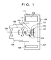
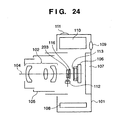
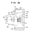
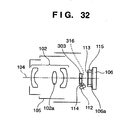
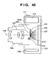
- the CMOS light-receiving sensor 106 is laid out on a prospective imaging plane of the photographing optical system 102, and a cover glass 106a of the CMOS light-receiving sensor 106 is fixed via a seal member 115. With this arrangement, dust will never attach on the cover glass 106a of the CMOS light-receiving sensor 106, and dust may attach to the entrance surface of the lens 102b. Since the distance from the light-receiving surface of the CMOS light-receiving sensor 106 to a dust position is sufficiently large, nearly no dust attached to the entrance surface of the 102b will be printed on the screen.
- the focus detection sensor 112 will be described below.
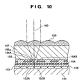
- Figs. 14 and 15 are partial sectional views of the focus detection visual field 121-1 shown in Fig. 8 .
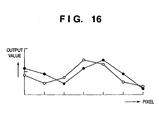
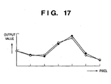
- Figs. 16 and 17 are graphs showing the output signal waveforms in out-of-focus and in-focus states of the focus detection sensor 112, which are input to the AF control circuit 140.
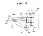
- Fig. 18 shows actual photographing light beams.
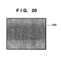
- the extinction parts 180a and 180b and the light splitting function surface 103a must be aligned with very high precision. That is, when gaps or overlapping portions are formed between the extinction parts 180a and 180b and the light splitting function surface 103a, an image which does not have uniform luminance on the image capturing range, and has impaired quality is obtained, as shown in Fig. 23A or 23B .
- the influence on an image becomes more conspicuous as the light splitting function surface 103a is brought closer to the imaging surface so as to attain a size reduction of the apparatus.
Landscapes
- Physics & Mathematics (AREA)
- General Physics & Mathematics (AREA)
- Optics & Photonics (AREA)
- Studio Devices (AREA)
- Focusing (AREA)
- Optical Elements Other Than Lenses (AREA)
- Automatic Focus Adjustment (AREA)
Claims (9)
- Appareil de capture d'images comprenant :un dispositif séparateur de faisceau lumineux (103, 203, 303, 403, 503) pour séparer une partie d'un faisceau lumineux se propageant vers un plan de formation d'image (106) qui fournit, pour la capture d'images, une image objet formée par un système optique de photographie (102) en des composantes de lumière dépendant de leurs directions de polarisation (S, P) ; etun dispositif de détection de focalisation (112) pour effectuer la détection de focalisation sur la base d'une composante polarisée (S) du faisceau lumineux séparé par ledit dispositif de séparation de faisceau lumineux (103, 203, 303, 403, 503) ;caractérisé par le fait qu'il comprend en outre un dispositif polarisant (116, 216, 316, 416, 516) qui est positionné entre ledit dispositif séparateur de faisceau lumineux (103, 203, 303, 403, 503) et le plan de formation d'image (106) et conçu pour faire en sorte que la quantité de lumière de la partie non séparée du faisceau lumineux se propageant vers le plan de formation d'image soit proche d'une quantité de lumière de la partie séparée du faisceau lumineux séparé par le dispositif séparateur de faisceau lumineux et se propageant vers le dispositif de détection de focalisation.
- Appareil selon la revendication 1 ou 2, dans lequel ledit dispositif séparateur de faisceau lumineux (103, 203, 303, 403, 503) comprend une surface ayant une fonction de séparation de faisceau lumineux (103a, 203a, 303a, 403a) qui est formée du côté d'une entrée de lumière (103b ; 203-1b, 203-2b ; 303-1b, 303-2b ; 403-1b, 403-2b) telle qu'un réseau de diffraction polarisant.
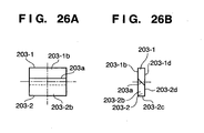
- Appareil selon la revendication 1 ou 2, dans lequel ledit dispositif séparateur de faisceau lumineux (103, 203, 303, 403, 503) a une forme obtenue en collant deux prismes (203-1, 203-2 ; 303-1, 303-2 ; 403-1, 403-2) sur la surface à fonction de séparation de faisceau lumineux (103-b ; 203-1b, 203-2b ; 303-1b, 303-2b ; 403-1b, 403-2b).
- Appareil selon l'une quelconque des revendications 1 à 3, dans lequel ledit dispositif séparateur de faisceau lumineux (103, 203, 303, 403, 503) comprend une surface (203-2b, 203-2c ; 303-2b, 302-2d ; 403-2b, 403-2d) pour réfléchir totalement le faisceau lumineux séparé sur un chemin optique vers ledit dispositif de détection de focalisation (112).
- Appareil selon la revendication 4, dans lequel ledit dispositif séparateur de faisceau lumineux (103) comprend un dispositif de rotation de la direction de polarisation (403-e) permettant de faire tourner la direction de polarisation du faisceau lumineux séparé jusqu'à ce que le faisceau lumineux séparé atteigne une surface de sortie de lumière (203-1d, 203-2d ; 303-1d, 303-2d, 403-1d, 403-2d) dudit dispositif séparateur de faisceau lumineux (103, 203, 303, 403, 503).
- Appareil selon l'une quelconque des revendications 1 à 5, dans lequel ledit dispositif polarisant (116, 216, 316, 416, 516) est ajouté à une surface de sortie de lumière dudit dispositif séparateur de faisceau lumineux.
- Appareil selon l'une quelconque des revendications 1 à 6, caractérisé par le fait qu'il comprend en outre un dispositif d'attaque pour insérer et rétracter de façon solidaire ledit dispositif séparateur de faisceau lumineux et ledit dispositif polarisant dans/par rapport au chemin optique (104) vers le plan de formation d'image (106).
- Appareil selon l'une quelconque des revendications 1 à 7, comprenant en outre un dispositif d'ajustement de composante de lumière polarisée (601) disposé entre ledit dispositif séparateur de faisceau lumineux (103, 203, 303, 403, 503) et le système optique de photographie (102) pour convertir une composante de lumière polarisée spécifique en de la lumière polarisée circulairement.
- Appareil selon l'une quelconque des revendications 1 à 8, dans lequel le dispositif polarisant (116, 216, 316, 416, 516) est conçu pour retirer, de la partie non séparée du faisceau lumineux se propageant vers le plan de formation d'image, une composante de lumière polarisée (S) sensiblement identique à la composante de lumière polarisée (S) séparée par ledit dispositif séparateur de faisceau lumineux (103) et se propageant vers le dispositif de détection de focalisation (112).
Applications Claiming Priority (1)
| Application Number | Priority Date | Filing Date | Title |
|---|---|---|---|
| JP2004317027A JP2006126652A (ja) | 2004-10-29 | 2004-10-29 | 撮像装置 |
Publications (2)
| Publication Number | Publication Date |
|---|---|
| EP1653257A1 EP1653257A1 (fr) | 2006-05-03 |
| EP1653257B1 true EP1653257B1 (fr) | 2008-07-16 |
Family
ID=35722395
Family Applications (1)
| Application Number | Title | Priority Date | Filing Date |
|---|---|---|---|
| EP05023075A Expired - Lifetime EP1653257B1 (fr) | 2004-10-29 | 2005-10-21 | Appareil de capture d'images |
Country Status (6)
| Country | Link |
|---|---|
| US (1) | US7515818B2 (fr) |
| EP (1) | EP1653257B1 (fr) |
| JP (1) | JP2006126652A (fr) |
| KR (1) | KR100739584B1 (fr) |
| CN (1) | CN100378486C (fr) |
| DE (1) | DE602005008163D1 (fr) |
Families Citing this family (19)
| Publication number | Priority date | Publication date | Assignee | Title |
|---|---|---|---|---|
| JP4720508B2 (ja) * | 2006-01-05 | 2011-07-13 | 株式会社ニコン | 撮像素子および撮像装置 |
| JP2008026789A (ja) * | 2006-07-25 | 2008-02-07 | Canon Inc | 撮像装置及びフォーカス制御方法 |
| US7925439B2 (en) * | 2006-10-19 | 2011-04-12 | Topcon Positioning Systems, Inc. | Gimbaled satellite positioning system antenna |
| US20080297649A1 (en) * | 2007-05-31 | 2008-12-04 | Igor Subbotin | Methods and apparatus providing light assisted automatic focus |
| US7812971B2 (en) * | 2007-06-28 | 2010-10-12 | Quality Vision International, Inc. | Multi color autofocus apparatus and method |
| JP5031475B2 (ja) | 2007-07-31 | 2012-09-19 | キヤノン株式会社 | ズームレンズ及びそれを有する撮影システム |
| US8786759B2 (en) | 2007-08-28 | 2014-07-22 | Motorola Mobility Llc | Method and apparatus for auto-focus using liquid crystal adaptive optics |
| JP5256711B2 (ja) * | 2007-11-28 | 2013-08-07 | 株式会社ニコン | 撮像素子および撮像装置 |
| JP5451111B2 (ja) | 2008-03-11 | 2014-03-26 | キヤノン株式会社 | 焦点検出装置およびそれを有する撮像装置 |
| CN101656258A (zh) * | 2008-08-20 | 2010-02-24 | 鸿富锦精密工业(深圳)有限公司 | 影像感测器封装结构、封装方法及相机模组 |
| CN101656259A (zh) * | 2008-08-20 | 2010-02-24 | 鸿富锦精密工业(深圳)有限公司 | 影像感测器封装结构、封装方法及相机模组 |
| JP5593602B2 (ja) * | 2008-09-24 | 2014-09-24 | ソニー株式会社 | 撮像素子および撮像装置 |
| US8508646B2 (en) * | 2008-12-22 | 2013-08-13 | Apple Inc. | Camera with internal polarizing filter |
| KR101700658B1 (ko) * | 2008-12-30 | 2017-02-01 | 삼성전자주식회사 | 초점 검출 장치가 구비된 일안 반사식 카메라 및 그의 촬영방법 |
| JP5229060B2 (ja) * | 2009-03-31 | 2013-07-03 | ソニー株式会社 | 撮像装置および焦点検出方法 |
| JP5825817B2 (ja) * | 2011-04-01 | 2015-12-02 | キヤノン株式会社 | 固体撮像素子及び撮像装置 |
| US20150369565A1 (en) * | 2014-06-20 | 2015-12-24 | Matthew Flint Kepler | Optical Device Having a Light Separation Element |
| JP6676040B2 (ja) * | 2015-04-08 | 2020-04-08 | マクセル株式会社 | 車両搭載カメラ |
| US20240248282A1 (en) * | 2023-01-25 | 2024-07-25 | Applied Materials, Inc. | Apparatus and methods for heating tunability in processing chambers |
Family Cites Families (16)
| Publication number | Priority date | Publication date | Assignee | Title |
|---|---|---|---|---|
| JPS5029869Y2 (fr) | 1971-03-22 | 1975-09-02 | ||
| JPS54145133A (en) * | 1978-05-02 | 1979-11-13 | Asahi Optical Co Ltd | Focus detector |
| US4561748A (en) * | 1983-05-20 | 1985-12-31 | Minolta Camera Kabushiki Kaisha | Focus detection device |
| JPS6318313A (ja) | 1986-07-10 | 1988-01-26 | Canon Inc | 焦点検出装置 |
| JPS6355501A (ja) | 1986-08-26 | 1988-03-10 | Nec Corp | 回折格子型光偏光板 |
| US5023723A (en) * | 1988-04-18 | 1991-06-11 | Canon Kabushiki Kaisha | Image sensing apparatus having plural image sensors and plural shutters |
| JPH04243382A (ja) * | 1991-01-17 | 1992-08-31 | Fuji Photo Optical Co Ltd | 電子スチルカメラ |
| JP2693302B2 (ja) | 1991-09-30 | 1997-12-24 | 三田工業株式会社 | 自己修復システムを有する画像形成装置 |
| US6952233B2 (en) * | 1992-07-23 | 2005-10-04 | Canon Kabushiki Kaisha | Video camera having a material element for controlling light transmission |
| JPH06175010A (ja) | 1992-12-03 | 1994-06-24 | Canon Inc | 光学装置 |
| JP3351011B2 (ja) | 1993-03-15 | 2002-11-25 | ソニー株式会社 | テープカセット |
| US5883872A (en) * | 1997-05-29 | 1999-03-16 | The Board Of Trustees Of The Leland Stanford Junior University | Near field magneto-optical recording system employing slit illumination |
| JP2001078318A (ja) * | 1999-09-06 | 2001-03-23 | Kawamura Electric Inc | ラックマウント型分電盤ユニット |
| JP3823659B2 (ja) * | 2000-02-04 | 2006-09-20 | セイコーエプソン株式会社 | プロジェクタ |
| JP2003140246A (ja) * | 2001-11-02 | 2003-05-14 | Canon Inc | カメラ |
| JP2003344897A (ja) * | 2002-05-30 | 2003-12-03 | Olympus Optical Co Ltd | 撮像光学系 |
-
2004
- 2004-10-29 JP JP2004317027A patent/JP2006126652A/ja not_active Withdrawn
-
2005
- 2005-10-21 EP EP05023075A patent/EP1653257B1/fr not_active Expired - Lifetime
- 2005-10-21 DE DE602005008163T patent/DE602005008163D1/de not_active Expired - Lifetime
- 2005-10-27 US US11/262,066 patent/US7515818B2/en not_active Expired - Fee Related
- 2005-10-28 CN CNB2005101160935A patent/CN100378486C/zh not_active Expired - Fee Related
- 2005-10-28 KR KR1020050102178A patent/KR100739584B1/ko not_active Expired - Fee Related
Also Published As
| Publication number | Publication date |
|---|---|
| KR100739584B1 (ko) | 2007-07-16 |
| CN100378486C (zh) | 2008-04-02 |
| CN1766689A (zh) | 2006-05-03 |
| KR20060052302A (ko) | 2006-05-19 |
| US20060092313A1 (en) | 2006-05-04 |
| US7515818B2 (en) | 2009-04-07 |
| JP2006126652A (ja) | 2006-05-18 |
| EP1653257A1 (fr) | 2006-05-03 |
| DE602005008163D1 (de) | 2008-08-28 |
Similar Documents
| Publication | Publication Date | Title |
|---|---|---|
| US7515818B2 (en) | Image capturing apparatus | |
| KR101280248B1 (ko) | 카메라 및 카메라 시스템 | |
| KR100875938B1 (ko) | 광학기기 및 빔 스플리터 | |
| US7538311B2 (en) | Image sensor and digital camera | |
| US7233359B2 (en) | Image sensing apparatus having image signals generated from light between optical elements of an optical element array | |
| JP4414486B2 (ja) | 撮像装置およびカメラ | |
| EP1067779A2 (fr) | Dispositif de prise de vue | |
| JP4983271B2 (ja) | 撮像装置 | |
| JP4857962B2 (ja) | 撮像装置 | |
| JP4858179B2 (ja) | 焦点検出装置および撮像装置 | |
| US7355154B2 (en) | Image sensing apparatus with movable light flux splitter and control method thereof | |
| US7665912B2 (en) | Image-taking apparatus and control method thereof | |
| US7474349B2 (en) | Image-taking apparatus | |
| JPH10164413A (ja) | 撮像装置 | |
| JP7005313B2 (ja) | 撮像装置及びその制御方法、プログラム、記憶媒体 | |
| JP2008129360A (ja) | 焦点検出装置及び撮像装置 | |
| JP2007065555A (ja) | 撮像装置 | |
| JP2006317918A (ja) | 撮像装置 | |
| JP4110152B2 (ja) | 撮像装置 | |
| JP2007187806A (ja) | 撮像装置 | |
| JP2007101965A (ja) | 撮像装置 |
Legal Events
| Date | Code | Title | Description |
|---|---|---|---|
| PUAI | Public reference made under article 153(3) epc to a published international application that has entered the european phase |
Free format text: ORIGINAL CODE: 0009012 |
|
| AK | Designated contracting states |
Kind code of ref document: A1 Designated state(s): AT BE BG CH CY CZ DE DK EE ES FI FR GB GR HU IE IS IT LI LT LU LV MC NL PL PT RO SE SI SK TR |
|
| AX | Request for extension of the european patent |
Extension state: AL BA HR MK YU |
|
| 17P | Request for examination filed |
Effective date: 20060811 |
|
| AKX | Designation fees paid |
Designated state(s): DE FR GB |
|
| 17Q | First examination report despatched |
Effective date: 20070228 |
|
| GRAP | Despatch of communication of intention to grant a patent |
Free format text: ORIGINAL CODE: EPIDOSNIGR1 |
|
| GRAS | Grant fee paid |
Free format text: ORIGINAL CODE: EPIDOSNIGR3 |
|
| GRAA | (expected) grant |
Free format text: ORIGINAL CODE: 0009210 |
|
| AK | Designated contracting states |
Kind code of ref document: B1 Designated state(s): DE FR GB |
|
| REG | Reference to a national code |
Ref country code: GB Ref legal event code: FG4D |
|
| REF | Corresponds to: |
Ref document number: 602005008163 Country of ref document: DE Date of ref document: 20080828 Kind code of ref document: P |
|
| PLBE | No opposition filed within time limit |
Free format text: ORIGINAL CODE: 0009261 |
|
| STAA | Information on the status of an ep patent application or granted ep patent |
Free format text: STATUS: NO OPPOSITION FILED WITHIN TIME LIMIT |
|
| 26N | No opposition filed |
Effective date: 20090417 |
|
| PGFP | Annual fee paid to national office [announced via postgrant information from national office to epo] |
Ref country code: FR Payment date: 20141027 Year of fee payment: 10 Ref country code: DE Payment date: 20141031 Year of fee payment: 10 Ref country code: GB Payment date: 20141021 Year of fee payment: 10 |
|
| REG | Reference to a national code |
Ref country code: DE Ref legal event code: R119 Ref document number: 602005008163 Country of ref document: DE |
|
| GBPC | Gb: european patent ceased through non-payment of renewal fee |
Effective date: 20151021 |
|
| PG25 | Lapsed in a contracting state [announced via postgrant information from national office to epo] |
Ref country code: DE Free format text: LAPSE BECAUSE OF NON-PAYMENT OF DUE FEES Effective date: 20160503 Ref country code: GB Free format text: LAPSE BECAUSE OF NON-PAYMENT OF DUE FEES Effective date: 20151021 |
|
| REG | Reference to a national code |
Ref country code: FR Ref legal event code: ST Effective date: 20160630 |
|
| PG25 | Lapsed in a contracting state [announced via postgrant information from national office to epo] |
Ref country code: FR Free format text: LAPSE BECAUSE OF NON-PAYMENT OF DUE FEES Effective date: 20151102 |