EP1654087B1 - Verfahren zum laserschweissen von beschichteten gliedern - Google Patents
Verfahren zum laserschweissen von beschichteten gliedern Download PDFInfo
- Publication number
- EP1654087B1 EP1654087B1 EP04769107.6A EP04769107A EP1654087B1 EP 1654087 B1 EP1654087 B1 EP 1654087B1 EP 04769107 A EP04769107 A EP 04769107A EP 1654087 B1 EP1654087 B1 EP 1654087B1
- Authority
- EP
- European Patent Office
- Prior art keywords
- laser
- sheets
- coated
- embossment
- welding
- Prior art date
- Legal status (The legal status is an assumption and is not a legal conclusion. Google has not performed a legal analysis and makes no representation as to the accuracy of the status listed.)
- Expired - Lifetime
Links
Images


Classifications
-
- B—PERFORMING OPERATIONS; TRANSPORTING
- B23—MACHINE TOOLS; METAL-WORKING NOT OTHERWISE PROVIDED FOR
- B23K—SOLDERING OR UNSOLDERING; WELDING; CLADDING OR PLATING BY SOLDERING OR WELDING; CUTTING BY APPLYING HEAT LOCALLY, e.g. FLAME CUTTING; WORKING BY LASER BEAM
- B23K26/00—Working by laser beam, e.g. welding, cutting or boring
- B23K26/20—Bonding
- B23K26/21—Bonding by welding
- B23K26/211—Bonding by welding with interposition of special material to facilitate connection of the parts
-
- B—PERFORMING OPERATIONS; TRANSPORTING
- B23—MACHINE TOOLS; METAL-WORKING NOT OTHERWISE PROVIDED FOR
- B23K—SOLDERING OR UNSOLDERING; WELDING; CLADDING OR PLATING BY SOLDERING OR WELDING; CUTTING BY APPLYING HEAT LOCALLY, e.g. FLAME CUTTING; WORKING BY LASER BEAM
- B23K26/00—Working by laser beam, e.g. welding, cutting or boring
- B23K26/20—Bonding
- B23K26/21—Bonding by welding
- B23K26/24—Seam welding
- B23K26/244—Overlap seam welding
-
- B—PERFORMING OPERATIONS; TRANSPORTING
- B23—MACHINE TOOLS; METAL-WORKING NOT OTHERWISE PROVIDED FOR
- B23K—SOLDERING OR UNSOLDERING; WELDING; CLADDING OR PLATING BY SOLDERING OR WELDING; CUTTING BY APPLYING HEAT LOCALLY, e.g. FLAME CUTTING; WORKING BY LASER BEAM
- B23K26/00—Working by laser beam, e.g. welding, cutting or boring
- B23K26/20—Bonding
- B23K26/32—Bonding taking account of the properties of the material involved
-
- B—PERFORMING OPERATIONS; TRANSPORTING
- B23—MACHINE TOOLS; METAL-WORKING NOT OTHERWISE PROVIDED FOR
- B23K—SOLDERING OR UNSOLDERING; WELDING; CLADDING OR PLATING BY SOLDERING OR WELDING; CUTTING BY APPLYING HEAT LOCALLY, e.g. FLAME CUTTING; WORKING BY LASER BEAM
- B23K26/00—Working by laser beam, e.g. welding, cutting or boring
- B23K26/60—Preliminary treatment
-
- B—PERFORMING OPERATIONS; TRANSPORTING
- B23—MACHINE TOOLS; METAL-WORKING NOT OTHERWISE PROVIDED FOR
- B23K—SOLDERING OR UNSOLDERING; WELDING; CLADDING OR PLATING BY SOLDERING OR WELDING; CUTTING BY APPLYING HEAT LOCALLY, e.g. FLAME CUTTING; WORKING BY LASER BEAM
- B23K2101/00—Articles made by soldering, welding or cutting
- B23K2101/006—Vehicles
-
- B—PERFORMING OPERATIONS; TRANSPORTING
- B23—MACHINE TOOLS; METAL-WORKING NOT OTHERWISE PROVIDED FOR
- B23K—SOLDERING OR UNSOLDERING; WELDING; CLADDING OR PLATING BY SOLDERING OR WELDING; CUTTING BY APPLYING HEAT LOCALLY, e.g. FLAME CUTTING; WORKING BY LASER BEAM
- B23K2101/00—Articles made by soldering, welding or cutting
- B23K2101/18—Sheet panels
-
- B—PERFORMING OPERATIONS; TRANSPORTING
- B23—MACHINE TOOLS; METAL-WORKING NOT OTHERWISE PROVIDED FOR
- B23K—SOLDERING OR UNSOLDERING; WELDING; CLADDING OR PLATING BY SOLDERING OR WELDING; CUTTING BY APPLYING HEAT LOCALLY, e.g. FLAME CUTTING; WORKING BY LASER BEAM
- B23K2101/00—Articles made by soldering, welding or cutting
- B23K2101/34—Coated articles ; Surface treated articles
-
- B—PERFORMING OPERATIONS; TRANSPORTING
- B23—MACHINE TOOLS; METAL-WORKING NOT OTHERWISE PROVIDED FOR
- B23K—SOLDERING OR UNSOLDERING; WELDING; CLADDING OR PLATING BY SOLDERING OR WELDING; CUTTING BY APPLYING HEAT LOCALLY, e.g. FLAME CUTTING; WORKING BY LASER BEAM
- B23K2103/00—Materials to be soldered, welded or cut
- B23K2103/08—Non-ferrous metals or alloys
-
- B—PERFORMING OPERATIONS; TRANSPORTING
- B23—MACHINE TOOLS; METAL-WORKING NOT OTHERWISE PROVIDED FOR
- B23K—SOLDERING OR UNSOLDERING; WELDING; CLADDING OR PLATING BY SOLDERING OR WELDING; CUTTING BY APPLYING HEAT LOCALLY, e.g. FLAME CUTTING; WORKING BY LASER BEAM
- B23K2103/00—Materials to be soldered, welded or cut
- B23K2103/50—Inorganic materials other than metals or composite materials
Definitions
- the present invention relates to a method of laser welding sheet metal having a layer of a coating material.
- weld joints are generally made by spot welding to join together the parts. Through the use of a high powered laser for welding, joints can be made more quickly and with better quality than other alternative joining techniques.
- the advantage of having a single side access, as opposed to requiring access to both sides of a work piece for conventional joining techniques, as well as no direct contact with the work piece make laser welding a desirable welding technique.
- two sheets that are to be joined are held together contacting each other along the area to be joined.
- a laser beam is then energized and swept across the area to be joined welding the sheets together by smelting or melting the metal in the area swept by the laser beam.
- a common problem associated with welding coated or galvanized sheet metal includes the vaporization of the zinc galvanized coating resulting in zinc gas explosion leading to a poor weld having defects or pits weakening the joints and creating a visually unacceptable part.
- JP 2002 361458 A discloses a method for a lap welding of zinc-based plated steel plates, wherein vapor pressure of zinc generated in the laser welding is decreased to prevent a weld defect when the zinc-based plated steel plates are lapped and welded with the laser beam.
- Metals having high corrosion resistance are dispersedly attached between inner surfaces of the lapped plates with a thermal spray method in order to suppress the decrease in the corrosion resistance due to a gap provided at the time of welding.
- EP 0 454 861 A1 relates to a laser welding method for zinc-plated steel sheets for welding the zinc-plated steel sheets to one another by laser.
- An intermediate layer for limiting the evaporation of zinc is formed between the zinc-plated steel sheets, wherein the intermediate layer is formed by spraying a solution of carbon graphite over the steel sheets.
- DE 101 12 744 A1 relates to a laser welding method for welding steel sheets, wherein a gap is provided between the steel sheets, and emissions being produced during welding can be removed by means of the gap.
- the gap is defined by small balls made of glass being arranged between the steel plates.
- IP 08141761 provides a method for laser welding of members by providing a clearance between the members, wherein a solvent containing bead-shaped spacers having the diameter equivalent to the dimension of the clearance is applied on lapped surfaces of the members to be welded. Gas being evaporated from plated layers of the members is discharged from the clearance formed by the spacers.
- DE 44 07 190 A1 disclosed a method for preparation of zinc-coated metal sheets for a subsequent step of laser welding. According to this method a projecting surface structure is created on the metal sheets by evaporating material of the metal sheets using high energy radiation.
- JP 2001162388 discloses a method of laser welding for plated steel plates wherein the plated steel plates are laminated to each other in a manner that a tip of a projecting part provided on one plated steel plate comes in contact with an upper surface of a second plated steel plate in order to define a gap.
- XP 000622042 Graham, M. P. et al.: "Nd:YAG Laser Beam Welding of Coated Steels Using a Modified Lap Joint Geometry", Welding Journal, American Welding Society, Miami, FL, US, vol. 75, no.
- JP 11226765 discloses a welding structure of galvanized steel sheets that exhausts an evaporation gas of a plating material of the galvanized steel sheets.
- the galvanized steel sheets are provided with a rugged face forming the exhaust passage for the evaporation gas.
- US 6 528 756 B2 discloses a laser lap welding process of welding together overlapped plated steel sheets. Parts of the upper plated steel sheet extending on the weld line are embossed to form bosses protruding toward the lower plated steel sheet. The bosses keep the joining surface of the upper plated steel sheet and the joining surface of the lower plated steel sheet spaced to form a gas discharge passage.
- Figure 1 is a diagram illustrating the steps of punching an embossment into the coated metal part forming the embossment of the embodiment of the invention
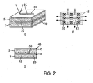
- Figure 2 is a diagram illustrating the joining of two parts by laser welding having the embossments of the embodiment of the invention
- Figure 3 illustrates the joining of two coated metal sheets having fine particles disbursed between according to a second embodiment which represents background art.
- FIG. 1 there is shown an illustration detailing the formation of a raised region 19 comprising an embossment 20 of the embodiment of the method of the present invention.
- a coated sheet metal 5 is placed in a press (not shown) which may be associated with an assembly line or may be offline as required.
- a press for use by the present invention does not require the presence of mating male and female dies as is commonly utilized in the art. Rather the press for use by the present invention requires only an anvil like surface opposite the punch 15; thereby, significantly lowering the cost of tooling.
- the coated metal sheet 5 comprises a metal core 7 having layers of coating 10 applied to at least one side and preferably both sides of the sheet 5.
- a four sided spear-shaped punch 15 is introduced above the coated sheet 5 to create an embossment 20 allowing for the venting of weld gases during a welding process.
- the spear-shaped punch 15 is a four sided body that preferably comprises a coated metal allowing for repeated use and strength.
- the spear-shaped punch 15 may be introduced in the upper or lower part of a tool to create the embossment 20 of the present invention.
- the spear-shaped punch 15 lances the metal sheet 5 from a direction corresponding to a first surface 23, causing the material on a periphery 25 to rise to a given height.
- the spear-shaped punch 15 does not penetrate the entire metal sheet 5 but only penetrates to a depth sufficient to cause a specific rise at the periphery 25 or edge of the embossment 20.
- the second surface 24 of the metal sheet 5, opposite the first surface 23, remains continuous and uninterrupted.
- the second surface may have a contour that is associated with the part, but does not include a raised region or depression from interaction with the punch 15.
- a raised edge of approximately 0,178 mm (0.007 inches) is formed by the spear-shaped punch 15.
- FIG. 2 the process of the embodiment of the invention utilizing punched embossments 20 to vent weld gases is shown.
- FIG 2E two metal sheets or parts 5 to be joined are shown, with one of them having the punched embossments 20 previously described with reference to Figure 1 .
- both parts 5 may include embossments 20 formed as described previously with reference to Figure 1 .
- a laser weld 30 is formed by energizing a beam and drawing it across the part at a weld joint 35. The laser heats the two metal sheets 5 smelting the parts 5 together along the weld joint 35 joining the two parts 5 together.
- the laser may be continuously drawn over the two metal sheets forming a continuous weld bead or may be energized intermittently to form welds in a specific location.
- FIG. 2F there is shown a top view of a part having an array 22 of embossments 20 formed by punching as previously described with reference to Figure 1 .
- the arrows indicate the flow of zinc gas formed by the introduction of the laser shown in Figure 2E .
- the array 22 or waffle area of embossments 20 allows the maximum flow of zinc gas formed by the laser to exit and flow without pressurizing and ejecting through the laser keyhole area of the weld joint 35.
- the joined part 40 is shown after the introduction of the laser, showing the zinc deposit 45 which forms in the weld area.
- the zinc gas vaporized by the joining process self-seals the gaps 50 between the two parts 5.
- the introduction of the laser should be limited to the minimum size area to be welded, due to the self-sealing effect of the solidification of the zinc gas.
- fine particles 70 are distributed on the surface 75 of at least one of the sheet metal parts 5 to be joined; thereby, introducing a gap 60 between the two parts 5.
- the fine particles 70 may be loosely blown on the surface 75 or can be plasma sprayed onto the surface 75 of the coated sheet metal part 5.
- the particles 70 will be permanently bonded to the surface 75 before the two sheets 5 are joined.
- the introduction of fine particles 70 between the two sheets 5 will result in a gap 60 between the two sheets roughly the diameter of the particles.
- zinc dust is preferably placed between the two parts 5 to maintain the coating and also create the gap 60 previously described with reference to the diameter of the particles 70.
- steel dust may be utilized creating a more permanent gap 60 due to the higher melting point of steel, as compared to zinc.
- a laser weld is formed by energizing a laser to locally smelt the metal of the two parts 5 to be joined resulting in a laser weld joint 35.
- the zinc gas formed in the area by the laser is allowed to flow between the particles 70 introduced between the two sheet metal parts 5 thereby preventing the pressurization of zinc gas resulting in ejection through the laser keyhole area.
- FIG 4G it can be seen that when zinc dust is utilized as the fine particle material 70, the zinc vaporizes and forms a deposit 80 in the weld area similar to the first embodiment.
Landscapes
- Engineering & Computer Science (AREA)
- Physics & Mathematics (AREA)
- Optics & Photonics (AREA)
- Plasma & Fusion (AREA)
- Mechanical Engineering (AREA)
- Laser Beam Processing (AREA)
Claims (3)
- Verfahren zum Laserschweißen einer Mehrzahl von beschichteten Metallblechen, mit den folgenden Schritten:Bereitstellen beschichteter Metallbleche (5) mit einander gegenüberliegenden ersten und zweiten Oberflächen Oberfläche (23, 24),Erzeugen eines erhöhten Bereichs (19) auf mindestens einem der beschichteten Bleche (5), wobei der erhöhte Bereich (19) auf der ersten Oberfläche (23) gebildet wird und wobei die zweite Oberfläche (24) kontinuierlich und ununterbrochen bleibt,Anordnen der beschichteten Bleche (5) übereinander, um dazwischen einen Spalt zu bilden, wobei der Spalt (50) durch den erhöhten Bereich (19) definiert ist,Anwenden eines Laserstrahls, um eine Laserschweißung zu bilden, wobei Gase, die während des Bildens der Laserschweißung erzeugt werden, durch den Spalt (50) entweichen,dadurch gekennzeichnet, dassder Schritt des Erzeugens eines erhöhten Bereichs das Stanzen mindestens einer Prägung bzw. Bosse (20) auf mindestens einem beschichteten Metallblech ohne Eindringen in das gesamte Metallblech (5), sondern lediglich durch Eindringen bis zu einer Tiefe, die ausreicht, um eine bestimmte Erhöhung an dem Umfang (25) der Prägung bzw. Bosse (20) hervorzurufen, derart, dass die Prägung bzw. Bosse (20) eine Vertiefung mit einer erhöhten Umfangskante aufweist, umfasst, wobei die zweite Oberfläche (24) keinen erhöhten Bereich und keine Vertiefung, die aus der Wechselwirkung mit dem Stanzstempel resultiert, aufweist.
- Verfahren zum Laserschweißen einer Mehrzahl von beschichteten Metallblechen nach Anspruch 1, wobei der Schritt des Erzeugens eines erhöhten Bereichs (19) das Stanzen einer Anordnung von Prägungen (20) umfasst.
- Verfahren zum Laserschweißen einer Mehrzahl von beschichteten Metallblechen nach Anspruch 1 und 2, wobei die erhöhte Umfangskante eine Dicke von etwa 0,178 mm (0,007 Zoll) aufweist.
Applications Claiming Priority (2)
| Application Number | Priority Date | Filing Date | Title |
|---|---|---|---|
| US49461003P | 2003-08-12 | 2003-08-12 | |
| PCT/IB2004/002528 WO2005014215A2 (en) | 2003-08-12 | 2004-08-06 | Method of laser welding coated members |
Publications (3)
| Publication Number | Publication Date |
|---|---|
| EP1654087A2 EP1654087A2 (de) | 2006-05-10 |
| EP1654087A4 EP1654087A4 (de) | 2008-10-29 |
| EP1654087B1 true EP1654087B1 (de) | 2013-10-30 |
Family
ID=34135349
Family Applications (1)
| Application Number | Title | Priority Date | Filing Date |
|---|---|---|---|
| EP04769107.6A Expired - Lifetime EP1654087B1 (de) | 2003-08-12 | 2004-08-06 | Verfahren zum laserschweissen von beschichteten gliedern |
Country Status (4)
| Country | Link |
|---|---|
| US (1) | US20060231534A1 (de) |
| EP (1) | EP1654087B1 (de) |
| CA (1) | CA2534251A1 (de) |
| WO (1) | WO2005014215A2 (de) |
Families Citing this family (6)
| Publication number | Priority date | Publication date | Assignee | Title |
|---|---|---|---|---|
| DE102005040200A1 (de) * | 2005-08-25 | 2007-03-01 | Volkswagen Ag | Abstandspulver für Laserschweißen |
| KR20090053082A (ko) * | 2007-11-22 | 2009-05-27 | 주식회사 성우하이텍 | 아연도금강판의 레이저 용접방법 |
| KR101059368B1 (ko) | 2008-09-26 | 2011-08-25 | 주식회사 성우하이텍 | 도금강판의 레이저 용접방법 |
| US9103358B2 (en) * | 2010-03-16 | 2015-08-11 | Eaton Corporation | Corrosion-resistant position measurement system and method of forming same |
| JP5633687B2 (ja) | 2010-10-25 | 2014-12-03 | スズキ株式会社 | 亜鉛めっき鋼板製部品のレーザ重ね溶接方法 |
| JP5630699B2 (ja) * | 2010-10-25 | 2014-11-26 | スズキ株式会社 | 亜鉛めっき鋼板製部品のレーザ重ね溶接方法 |
Citations (1)
| Publication number | Priority date | Publication date | Assignee | Title |
|---|---|---|---|---|
| US6528756B2 (en) * | 2000-03-30 | 2003-03-04 | Fuji Jukogyo Kabushiki Kaisha | Laser lap welding process of welding together overlapped plated steel sheets |
Family Cites Families (23)
| Publication number | Priority date | Publication date | Assignee | Title |
|---|---|---|---|---|
| US4005991A (en) * | 1971-12-29 | 1977-02-01 | Toyo Kogyo Co., Ltd. | Metal made of steel plate and aluminum material |
| JPS5135547B2 (de) * | 1973-04-10 | 1976-10-02 | ||
| JPS56134026A (en) * | 1980-03-25 | 1981-10-20 | Tsubakimoto Chain Co | Blanking method |
| IT1182277B (it) * | 1984-09-20 | 1987-10-05 | Prima Progetti Spa | Metodo per la saldatura laser di lamiere metalliche protette con materiali a bassa temperatura di vaporizzazione |
| WO1990011161A1 (de) * | 1989-03-22 | 1990-10-04 | Fraunhofer-Gesellschaft zur Förderung der angewandten Forschung e.V. | Anordnung zum schweissen von beschichteten werkstücken mittels laserstrahlung |
| DE3933408A1 (de) * | 1989-10-06 | 1990-08-30 | Daimler Benz Ag | Ueberlapp- oder steg-schweissnaht fuer verzinkte bleche |
| JPH03165994A (ja) | 1989-11-22 | 1991-07-17 | Fanuc Ltd | 亜鉛メッキ鋼板のレーザ溶接方法 |
| US5284043A (en) * | 1992-09-29 | 1994-02-08 | Amada Manufacturing America Inc. | Method and device for separating a contoured product from sheet metal |
| US5454480A (en) * | 1993-10-21 | 1995-10-03 | Morris Holmes & Co. | Flangeless fuel tank |
| DE4407190A1 (de) | 1994-03-04 | 1995-09-07 | Thyssen Laser Technik Gmbh | Verfahren zum Vorbereiten der Fügebereiche beschichteter Werkstücke zum Schweißen mit Laserstrahlung und Überlappstoß zum Schweißen beschichteter Werkstücke |
| US5637242A (en) * | 1994-08-04 | 1997-06-10 | Electro-Plasma, Inc. | High velocity, high pressure plasma gun |
| JPH08141761A (ja) | 1994-11-18 | 1996-06-04 | Daihatsu Motor Co Ltd | レーザー溶接方法 |
| EP0899053A3 (de) * | 1997-08-29 | 2000-04-05 | Sintokogio Ltd. | Plattiertes Produkt und Verfahren und Vorrichtung zu dessen Herstellung |
| WO1999011399A1 (en) * | 1997-09-04 | 1999-03-11 | Amada Metorecs Company, Limited | Mold for forming projection |
| JPH11226765A (ja) * | 1998-02-19 | 1999-08-24 | Isuzu Motors Ltd | メッキ鋼板のレーザ溶接構造 |
| JP2001162388A (ja) | 1999-12-08 | 2001-06-19 | Honda Motor Co Ltd | めっき鋼板のレーザ溶接方法および溶接構造 |
| US6342272B1 (en) * | 2000-04-21 | 2002-01-29 | The United States Of America As Represented By The Secretary Of The Air Force | Multi-layer corrosion resistant coatings |
| CA2356512C (en) * | 2000-09-07 | 2009-03-10 | Inocon Technologie Ges.M.B.H. | A method for closing and/or joining a connecting joint or joining seam between two pieces of galvanized sheet metal |
| DE10112744A1 (de) | 2001-03-14 | 2002-09-19 | Volkswagen Ag | Laserschweißverfahren |
| JP2002361458A (ja) | 2001-06-07 | 2002-12-18 | Nippon Steel Corp | 耐食性に優れた亜鉛系めっき鋼板の重ね合わせレーザ溶接方法 |
| US6592947B1 (en) * | 2002-04-12 | 2003-07-15 | Ford Global Technologies, Llc | Method for selective control of corrosion using kinetic spraying |
| JP2003334681A (ja) * | 2002-05-22 | 2003-11-25 | Toyota Motor Corp | 表面処理鋼板の重ね溶接方法 |
| EP1516691B1 (de) * | 2002-06-27 | 2015-06-03 | Nippon Steel & Sumitomo Metal Corporation | vERFAHREN ZUM SCHWEISSEN |
-
2004
- 2004-08-06 CA CA002534251A patent/CA2534251A1/en not_active Abandoned
- 2004-08-06 EP EP04769107.6A patent/EP1654087B1/de not_active Expired - Lifetime
- 2004-08-06 US US10/567,877 patent/US20060231534A1/en not_active Abandoned
- 2004-08-06 WO PCT/IB2004/002528 patent/WO2005014215A2/en not_active Ceased
Patent Citations (1)
| Publication number | Priority date | Publication date | Assignee | Title |
|---|---|---|---|---|
| US6528756B2 (en) * | 2000-03-30 | 2003-03-04 | Fuji Jukogyo Kabushiki Kaisha | Laser lap welding process of welding together overlapped plated steel sheets |
Also Published As
| Publication number | Publication date |
|---|---|
| EP1654087A2 (de) | 2006-05-10 |
| EP1654087A4 (de) | 2008-10-29 |
| WO2005014215A2 (en) | 2005-02-17 |
| US20060231534A1 (en) | 2006-10-19 |
| CA2534251A1 (en) | 2005-02-17 |
| WO2005014215A3 (en) | 2005-05-12 |
Similar Documents
| Publication | Publication Date | Title |
|---|---|---|
| US7315009B2 (en) | Material for welding and welded article | |
| US10052720B2 (en) | Method of laser welding coated steel sheets with addition of alloying elements | |
| JP5224349B2 (ja) | 薄板のレーザー溶接方法 | |
| EP3620255B1 (de) | Verfahren zum herstellen einer geschweissten rohling | |
| JP2918829B2 (ja) | 燃料タンクの製造方法、レーザ溶接体及び燃料タンク | |
| JP2000197969A (ja) | 一体化成形用ブランクおよびその成形方法 | |
| JP2010264503A (ja) | 鋼板の重ね溶接方法及び鋼板の重ね溶接継手 | |
| EP1184126A3 (de) | Laserlampeschweissverfahren zum Zusammenschweissen von überlappten Stahlblechen | |
| WO1999008829A1 (en) | Method of laser beam welding of zinc-coated steel sheet | |
| MXPA04002020A (es) | Metodo para realizar una operacion de soldadura laser en acero recubierto con zinc. | |
| CN112351855A (zh) | 镀敷钢板的接合方法以及接合构造体 | |
| EP1193021B2 (de) | Verbinden von Strukturkomponenten mittels Schweissen | |
| US20060231534A1 (en) | Method of laser welding coated members | |
| JP4409038B2 (ja) | めっき鋼板の重ねレーザ溶接方法 | |
| JP6885088B2 (ja) | 溶接継手を有する鋼部材及びその製造方法 | |
| JP5292921B2 (ja) | レーザ溶接方法およびレーザ溶接装置 | |
| JPH0947873A (ja) | 重ね合わせ溶接方法、装置及び溶接鋼板 | |
| JPH08141761A (ja) | レーザー溶接方法 | |
| JPS62296982A (ja) | レ−ザ溶接方法 | |
| EP1640104A2 (de) | Verfahren zum Schweissen von aus galvanisiertem Stahl hergestellten Elementen | |
| US20090316418A1 (en) | Component With a Weld Projection Having a Projection and Lamp Housing Part Comprising a Component with a Weld Projection | |
| US12179279B2 (en) | Method for producing a joining connection between metal sheets | |
| WO2006105658A1 (en) | Laser welding of galvanized steel | |
| JPH1024374A (ja) | 滑らかな段差部を有する接合鋼板の製造方法 | |
| JPH0359790B2 (de) |
Legal Events
| Date | Code | Title | Description |
|---|---|---|---|
| PUAI | Public reference made under article 153(3) epc to a published international application that has entered the european phase |
Free format text: ORIGINAL CODE: 0009012 |
|
| 17P | Request for examination filed |
Effective date: 20060213 |
|
| AK | Designated contracting states |
Kind code of ref document: A2 Designated state(s): AT DE |
|
| R17P | Request for examination filed (corrected) |
Effective date: 20060213 |
|
| RIC1 | Information provided on ipc code assigned before grant |
Ipc: B23K 26/32 20060101ALI20060807BHEP Ipc: B23K 26/16 20060101ALI20060807BHEP Ipc: B23K 26/20 20060101AFI20060807BHEP |
|
| DAX | Request for extension of the european patent (deleted) | ||
| RBV | Designated contracting states (corrected) |
Designated state(s): AT DE |
|
| RBV | Designated contracting states (corrected) |
Designated state(s): AT DE |
|
| A4 | Supplementary search report drawn up and despatched |
Effective date: 20080925 |
|
| 17Q | First examination report despatched |
Effective date: 20081230 |
|
| GRAP | Despatch of communication of intention to grant a patent |
Free format text: ORIGINAL CODE: EPIDOSNIGR1 |
|
| INTG | Intention to grant announced |
Effective date: 20130516 |
|
| GRAS | Grant fee paid |
Free format text: ORIGINAL CODE: EPIDOSNIGR3 |
|
| GRAA | (expected) grant |
Free format text: ORIGINAL CODE: 0009210 |
|
| AK | Designated contracting states |
Kind code of ref document: B1 Designated state(s): AT DE |
|
| REG | Reference to a national code |
Ref country code: AT Ref legal event code: REF Ref document number: 638327 Country of ref document: AT Kind code of ref document: T Effective date: 20131115 |
|
| REG | Reference to a national code |
Ref country code: DE Ref legal event code: R096 Ref document number: 602004043691 Country of ref document: DE Effective date: 20131224 |
|
| REG | Reference to a national code |
Ref country code: DE Ref legal event code: R097 Ref document number: 602004043691 Country of ref document: DE |
|
| PLBE | No opposition filed within time limit |
Free format text: ORIGINAL CODE: 0009261 |
|
| STAA | Information on the status of an ep patent application or granted ep patent |
Free format text: STATUS: NO OPPOSITION FILED WITHIN TIME LIMIT |
|
| 26N | No opposition filed |
Effective date: 20140731 |
|
| REG | Reference to a national code |
Ref country code: DE Ref legal event code: R097 Ref document number: 602004043691 Country of ref document: DE Effective date: 20140731 |
|
| REG | Reference to a national code |
Ref country code: DE Ref legal event code: R082 Ref document number: 602004043691 Country of ref document: DE Representative=s name: GLAWE DELFS MOLL PARTNERSCHAFT MBB VON PATENT-, DE |
|
| PGFP | Annual fee paid to national office [announced via postgrant information from national office to epo] |
Ref country code: AT Payment date: 20200728 Year of fee payment: 17 |
|
| REG | Reference to a national code |
Ref country code: AT Ref legal event code: MM01 Ref document number: 638327 Country of ref document: AT Kind code of ref document: T Effective date: 20210806 |
|
| PG25 | Lapsed in a contracting state [announced via postgrant information from national office to epo] |
Ref country code: AT Free format text: LAPSE BECAUSE OF NON-PAYMENT OF DUE FEES Effective date: 20210806 |
|
| P01 | Opt-out of the competence of the unified patent court (upc) registered |
Effective date: 20230517 |
|
| PGFP | Annual fee paid to national office [announced via postgrant information from national office to epo] |
Ref country code: DE Payment date: 20230613 Year of fee payment: 20 |
|
| REG | Reference to a national code |
Ref country code: DE Ref legal event code: R071 Ref document number: 602004043691 Country of ref document: DE |