EP1654976B1 - Endoscope à progression alternée - Google Patents
Endoscope à progression alternée Download PDFInfo
- Publication number
- EP1654976B1 EP1654976B1 EP05022928.5A EP05022928A EP1654976B1 EP 1654976 B1 EP1654976 B1 EP 1654976B1 EP 05022928 A EP05022928 A EP 05022928A EP 1654976 B1 EP1654976 B1 EP 1654976B1
- Authority
- EP
- European Patent Office
- Prior art keywords
- endoscope
- tube
- endoscope shaft
- fluid
- hose
- Prior art date
- Legal status (The legal status is an assumption and is not a legal conclusion. Google has not performed a legal analysis and makes no representation as to the accuracy of the status listed.)
- Expired - Lifetime
Links
Images



Classifications
-
- A—HUMAN NECESSITIES
- A61—MEDICAL OR VETERINARY SCIENCE; HYGIENE
- A61B—DIAGNOSIS; SURGERY; IDENTIFICATION
- A61B1/00—Instruments for performing medical examinations of the interior of cavities or tubes of the body by visual or photographical inspection, e.g. endoscopes; Illuminating arrangements therefor
- A61B1/005—Flexible endoscopes
- A61B1/01—Guiding arrangements therefore
-
- A—HUMAN NECESSITIES
- A61—MEDICAL OR VETERINARY SCIENCE; HYGIENE
- A61B—DIAGNOSIS; SURGERY; IDENTIFICATION
- A61B1/00—Instruments for performing medical examinations of the interior of cavities or tubes of the body by visual or photographical inspection, e.g. endoscopes; Illuminating arrangements therefor
- A61B1/00064—Constructional details of the endoscope body
- A61B1/00071—Insertion part of the endoscope body
- A61B1/0008—Insertion part of the endoscope body characterised by distal tip features
- A61B1/00082—Balloons
-
- A—HUMAN NECESSITIES
- A61—MEDICAL OR VETERINARY SCIENCE; HYGIENE
- A61B—DIAGNOSIS; SURGERY; IDENTIFICATION
- A61B1/00—Instruments for performing medical examinations of the interior of cavities or tubes of the body by visual or photographical inspection, e.g. endoscopes; Illuminating arrangements therefor
- A61B1/00064—Constructional details of the endoscope body
- A61B1/00071—Insertion part of the endoscope body
- A61B1/0008—Insertion part of the endoscope body characterised by distal tip features
- A61B1/00085—Baskets
-
- A—HUMAN NECESSITIES
- A61—MEDICAL OR VETERINARY SCIENCE; HYGIENE
- A61B—DIAGNOSIS; SURGERY; IDENTIFICATION
- A61B1/00—Instruments for performing medical examinations of the interior of cavities or tubes of the body by visual or photographical inspection, e.g. endoscopes; Illuminating arrangements therefor
- A61B1/00147—Holding or positioning arrangements
- A61B1/00154—Holding or positioning arrangements using guiding arrangements for insertion
-
- A—HUMAN NECESSITIES
- A61—MEDICAL OR VETERINARY SCIENCE; HYGIENE
- A61B—DIAGNOSIS; SURGERY; IDENTIFICATION
- A61B1/00—Instruments for performing medical examinations of the interior of cavities or tubes of the body by visual or photographical inspection, e.g. endoscopes; Illuminating arrangements therefor
- A61B1/00147—Holding or positioning arrangements
- A61B1/0016—Holding or positioning arrangements using motor drive units
Definitions
- the invention relates to an endoscope with alternating propulsion for moving an endoscope shaft along a channel-like cavity according to the preamble of patent claim 1.
- Endoscopes have become an important tool in the art and especially in medicine to inspect channel-like cavities that are otherwise accessible only with considerable intervention.
- endoscopes are used to examine the esophagus, stomach, duodenum from the stomach, intestine, anus, urethra, bladder and urethra.
- Such endoscopes are equipped at their front end with a lighting device and with an optical system for the visual detection of the area in front of the cavity.
- the optical information acquired at the front end of the endoscope is normally either transmitted back to its operating end by means of a fiber optic through the endoscope or is detected by means of an optical sensor chip at the front end, guided backwards through the endoscope by an electrical line and made visible on a screen ,
- an information transmission by radio from the front end to the operator end is conceivable.
- endoscopes usually have a so-called working channel through which diverse Working instruments can be introduced and operated. For example, small forceps for taking tissue samples, biopsy needles, heatable cutting wires, small scissors, coagulation electrodes or the like are introduced to perform possibly surgical measures on damaged tissue.
- a fluid conduit for irrigation fluid and operating wires or fluid conduits for angling the endoscope tip in several directions are typically present. These operating wires or fluid conduits are in turn guided within the endoscope shaft to its front and / or distal end.
- U.S. Patent No. 5,306,988 discloses DE 42 44 990 a corresponding device.
- an everting tube is moved along with the endoscope shaft during the forward movement of the endoscope shaft into a cavity and, when reaching one distal end, is initially pushed outward, so that the section of the everting tube, which is turned outwards, rests against the cavity wall.
- the advantage of this stationary everting tube section is that damage to the cavity wall can be reduced.
- outer wall curvature and inner wall each denote in relation to a fictitious center of a cavity bend each further outward or inward cavity wall.
- the DE 36 30 660 A1 discloses a coloscope consisting of two main elements, namely a sliding and a cladding tube, which are each provided at their distal end with expandable balloons. These balloons are inflated alternately, supporting themselves on the intestinal wall. They thus form a kind of abutment where tensile forces are introduced into the intestinal wall, which arise when pulling in each of the currently not supported main element.
- propulsion of a kind of "inchworm" movement in which alternately a rear and a front bearing is supported on a fixed object. In this case, all feed forces are introduced into the intestinal wall, which leads to pain in the patient.
- the US 6,007,482 as well as the US 4,557,621 also each reveal an endoscope, which is moved forward in a cavity to be examined according to the "inchworm" movement principle.
- the US 6,007,482 and the US 4,557,621 basically the DE 36 30 660 A1 with all the disadvantages involved.
- Endoscope shanks must meet in principle two mutually opposite conditions. First, they must be pushed into a cavity to be examined, which requires a certain stiffness of the shaft so as not to buckle. On the other hand, they must be flexible enough to be able to follow bends. The latter condition is particularly important in examinations of intestinal walls, since too low a flexibility results in an endoscope shaft bulging out of the bowel wall at a bowel obstruction to be passed, which, as stated above, leads to considerable pain.
- an endoscope shaft is driven by means of an auxiliary device preferably in the form of a hose or hose device in a channel-like cavity, which the Sheath surrounding the outside wall. It is crucial that this hose / hose device is at least temporarily stiffer or can be made, as the preferably highly flexible endoscope shaft. As a result of this configuration, buckling of the endoscope shaft is prevented by the tube / hose device surrounding it and supporting it; at the same time, a sufficiently high degree of flexibility can still be maintained.
- the core of the invention for implementing the above basic concept of the invention is therefore to make the outside hose / tube auxiliary relatively movable to the endoscope shaft lying therein, wherein the endoscope shaft as the first element and the auxiliary device as the second element are alternately with respect to a cavity to be inspected ie does not move forward, and at the same time the just non-resting element is vorreibreibbar under guidance along the straight resting element into the cavity.
- one of the two elements namely the hose / hose device surrounding the endoscope shaft, only temporarily receives a greater rigidity than that of the endoscope shaft.
- the basic stiffness of the tube is less than that of the endoscope shaft.
- the endoscope shaft serves as a guide element, ie, the endoscope shaft is able to guide the relative to this moving tube by curvatures.
- the hose has a device by means of which the flexible hose can be stiffened, in particular to a stiffness which is greater than that of the endoscope shaft.
- the hose serves as a guide element, ie, the hose is able to guide the relative to this moving shaft by curvatures.
- a variety of such devices for selectively (temporarily) (alternately) stiffening the hose and / or the shaft are available to the person skilled in the art.
- the tube is lined or covered with fluid cushions whose contents (volume) can optionally be clamped and released again.
- the endoscope according to the invention consists of a flexible endoscope shaft 1, at the distal end of an endoscope head 2 is attached and at the other end (operator end) operating and possibly information evaluation devices (not shown) are connected.
- This endoscope head 2 can be formed with various devices 3, such as an optic, a lighting device, a working channel for various tools, etc.
- the endoscope head 2 is preferably connected to the flexible endoscope shaft 1 via a movable distal end section 4 (hereinafter referred to as "deflecting").
- Deflecting 4 may preferably be curved in multiple directions in response to instructions from the operating end (not shown) of the endoscope at different radii of curvature.
- Use here is a conventional Deflecting, such as in the applications DE 102 09 986 A1 or DE 100 10 932 A1 described. For the exact operation and execution of this Deflecting is made to these applications.
- the deflecting can be curved by control signals or pressures from the operator's end and thus can be stiffened either in this curved position or in a non-curved position.
- the lines (not shown) for driving the Deflecting 4 and the devices 3 and possibly existing working channels for operating and introducing tools used on the endoscope head 2 extend within the deflecting 4 and the endoscope shaft 1 to the operator's back.
- the endoscope shaft 1 is preferably surrounded up to the point at which the endoscope shaft 1 is connected to the deflecting 4 by a preferably single-walled tube 5, so that the deflecting 4 with the endoscope head 2 connected thereto protrude at the front end (distal end) of the tube 5 ,
- the tube consists in this embodiment of EPTFE material whose wall thickness is 2 - 3mm.
- a spiral spring can be introduced into the tubular EPTFE material in such a way that the EPTFE tube material runs conically to the coil spring and the spring wire (not necessarily made of spring steel) is completely embedded in the EPTFE material between the tube inner wall and the tube outer wall.
- the coil spring conically to the EPTFE tubing, wherein the coil spring is wrapped by the EPTFE tubing and connected thereto, so that the coil spring is exposed to the inside.
- the coil spring is not essential and it is also an embodiment of the tube 5 without coil spring conceivable.
- the tubing is also not limited to said EPTFE material and may be formed of other materials such as silicone.
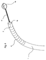
- the tube 5 is provided in this embodiment on the outer periphery with fluid pad 6.
- These fluid pads 6 are preferably formed in an elongated shape and widened at the central portions 7.
- the fluid pads 6 at their front and Rear end of a narrow tongue-shaped end portion 8.
- the fluid cushions 6 are each arranged in groups consisting of three fluid cushions 6.
- the fluid pads 6 of this group of three are aligned in the longitudinal direction parallel to each other about the outer circumference of the tube 5 so that the side surfaces of the fluid pads 6 touch at their middle portion 7 or form a small gap. That is, this three-group of fluid pads is distributed around the outer circumference of the tube such that the mid-perpendiculars of the fluid pads 6 intersect with the central axis of the endoscope shaft 1 and form an angle of 120 degrees to the mid-perpendicular of the adjacent fluid pad 6.
- the tongue-shaped end portions 8 protrude at a distance of 120 ° (in a plane perpendicular to the tube central axis) distributed around the outer circumference of the tube 5 to the front and rear. Since the end portions 8 are narrower than the central portions 7, an end portion to each adjacent end portion is further spaced than the respective central portions 7. Thus, each bulge 9 is formed between two adjacent end portions.
- Adjacent to the above triple group of fluid pillows 6, before and behind this another three-way group of fluid pillows 6 is arranged such that the end portions 8 of the latter triple group of fluid pillows 6 are inserted into the protrusions of the former triple group of fluid pillows 6 , That is, longitudinally adjacent fluid cushion groups are circumferentially offset in a plane perpendicular to the tube central axis by 60 °.
- the fluid pads 6 are arranged according to the manner just described about a 50cm long end portion of the tube 5, starting from the front end thereof.
- the fluid cushions 6 are pressurized via supply lines (not shown), which run in the wall or on the inner or outer circumference of the tube 5 to the rear to the operating end.
- the flexibility of the tube 5 can be changed.
- the air cushion 6 put on the cavity wall, so that the tube 5 is fixed relative to the cavity wall.
- a pressurization of the fluid cushion 6 or a relaxation of incompressible fluid in the fluid cushion 6 thus allows the hose 5 optionally to be provided with a flexibility which is smaller or larger than the flexibility of the endoscope shaft 1 and at the same time the tube 5 with respect to the cavity wall in a fixed or movable state.
- the tube 5 can be supported on the entire circumference of the cavity wall, without losing its flexibility.
- Fig. 3 shows the endoscope in a state in which it has already been moved a little way into the cavity.
- Reference numeral 10 denotes a first drive means 10 for advancing the tube 5.
- the drive means 10 consists of a pair of drive wheels 11 with their channel-shaped Outer circumference from two sides with the hose 5 in frictional engagement. These drive wheels 11 are driven by a not shown electric motor.
- the tube 5 is attached at its rear end to a plate-like part 12. Between the first drive device 10 and the plate 12 of the endoscope shaft 1 is placed with the surrounding tube 5 to a dished shape 15. In the region of the plate 12 lubricant could be pressed into the space between the endoscope shaft 1 and the tube 5.
- a pair of drive wheels 13 is preferably provided, which are with its groove-shaped outer periphery of two sides with the endoscope shaft 1 in frictional engagement.
- the first drive device 10 is firmly connected to the second drive device 14, so that these drive devices can not move relative to each other.
- these drive means 10, 14 as possible with respect to the cavity to be examined to install that they do not move relative to the cavity.
- the surface of the drive wheels 11 at its groove-shaped outer periphery is designed such that a large friction between the drive wheels 11 and the tube 5 is made.
- Either lubricant is introduced between the tube 5 and the endoscope shaft 1 and / or the endoscope shaft 1 is coated in such a way (eg Teflon) that between tube 5 and Endoscopy 1 a very low friction occurs.
- Teflon Teflon
- FIG. 3a is the endoscope shaft 1 and the tube 5 at a certain point of a cavity to be inspected.
- the fluid pads 6 are filled with fluid via the pump (not shown) and thus abut the wall of the cavity.
- the tube 5 is fixed with respect to the cavity wall.
- the tube 5 is held by the drive device 10.
- the fluid supply is controlled such that the tube 5 with a completed fluid pad filling less flexibility (higher stiffness) than the endoscope shaft first
- the endoscope shaft 1 is advanced by means of the second drive unit 14.
- the first drive unit 10 stands still. This process is in FIG. 3b shown schematically.
- the tube 5 serves as a support channel for the movement of the endoscope shaft 1. This support effect is supported by the lower flexibility of the tube 5.
- the procedure is as follows.
- the cavity bending at the endoscope head 2 can be detected by sensors or by the optics installed in the endoscope head.
- the curvature of the deflecting 4 can be adjusted and adjusted to the radius of curvature of the cavity bend. Thus, little or no pressure is exerted on the outer curvature wall of the cavity.
- the deflecting 4 is straightened again as the endoscope head 2 advances further.
- the endoscope shaft 1 resting with respect to the cavity acts with its lower flexibility (higher basic rigidity compared to that of the tube 5) as a rail for the tube 5. Since the endoscope shaft 1 is located further in the cavity than the tube 5 has the endoscope shaft 1 at the time when the tube 5 is set in motion, already assumed the shape of the cavity, the tube 5 passes through in a cycle, with all possible bends. Thus, when the tube 5 follows the shape of the endoscope shaft 1, the force with which the tube 5 presses against the curvature outer wall can thus be reduced. The force otherwise pressing against the curvature outer wall is derived in the present invention from the endoscope shaft 1 which is stiffer in this state. At the same time, for medical use this means that the pain perceived by the patient does not arise or diminish.
- the tube 5 becomes, as in Figure 3c shown, preferably so far moved forward until the front end of the tube 5 reaches the junction between the tube 5 and Deflecting 4.
- the forward movement of the endoscope is started with a new cycle FIG. 3a continued. That is, the fluid pads 6 are flooded again, so that the tube 5 relative to Cavity wall is fixed. Subsequently, the endoscope shaft 1 is moved forward, etc.
- the backward movement of the endoscope can be accomplished by reversing the forward movement procedure. Another possibility would be to relax the fluid pads and release the deflecting 4 so that it is free to move. Subsequently, the endoscope shaft could be pulled out together with the tube 5 from the cavity.
- the previously described principle of alternating propulsion of the endoscope can be used or discontinued at any stage in the forward movement of the endoscope. That is, the The endoscope shaft and the auxiliary device can first be moved into the channel-like cavity and the alternating propulsion is only used at a certain location of the hollow space that is difficult to pass through. After passing this point (eg strong cavity bends) is also a shutdown and a renewed activation of the alternating propulsion during further forward movement possible.
- the shape of the fluid pads has been specified.
- the fluid pads could be formed by a ring surrounding the tube 5 in a plane perpendicular to the longitudinal axis of the tube.
- the ring would have hollow inside and divided into several chambers. The individual chambers thus created would then correspond to the function of a respective fluid pad 6 and would be similar to pressurize the fluid pad via leads with pressure and relax.
- channel-like cavities which extend in the longitudinal direction on the outer circumference, on the inner circumference or in the wall of the hose or the auxiliary device.
- these channel-like cavities could be formed spirally on the outer circumference, on the inner circumference or in the wall of the hose or the auxiliary device.
- a change in flexibility of the endoscope shaft 1 can preferably be realized by means of these channel-like cavities extending in the longitudinal direction or spirally along the endoscope shaft 1, by arranging the channel-like cavities on the outer periphery, in the radially outer region or in a working channel. to Flexibility change of the auxiliary device and / or the endoscope shaft is then pressurized or released in the cavities located fluid or medium.
- the length of the front end portion of the tube 5, are placed over the fluid pad 6, in the preferred embodiment, about 50cm. However, it is obvious that the length of this front end portion can be changed accordingly.
- the fluid pads 6 are mounted in the preferred embodiment on the outer circumference of the tube 5. An embedding of the fluid cushion in the hose wall is also possible.
- a coil spring As an alternative to the tube 5 could be used in the preferred embodiment, a coil spring. This spiral spring could be used with arranged on the outer circumference fluid pad as an auxiliary device.
- the arrangement of the fluid pads was carried out in the preferred embodiment in groups of three fluid pads. However, the number of fluid pads per group can also be increased.
- flexibility change of the tube 5 by means of the pressurization or relaxation of the fluid pad 6 can also be performed in several stages or even continuously. That is, the pressurization of the fluid pads 6 could be controlled so that they are pressurized the higher the further the endoscope head 2 is moved in a cavity bend with resting tube 5, that is, the more the deflecting 4 is bent during the forward movement.
- the front end (distal end) of the tube 5 in the retracted state of the endoscope shaft 1 (state excludes Fig. 3a ) with the rear end of Deflectings 4 from.
- the present invention is not limited to this, and the front end of the tube 5 can also terminate further behind the deflecting 4 in the retracted state of the endoscope shaft 1.
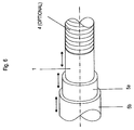
- the tube 5 is preferably made of highly stretchable (highly flexible) EPTFE material is, the hose can be greatly expanded without changing its diameter or wall thickness. Therefore, for example, in the preferred embodiment, the tube 5 may extend to the endoscope head 2 where it may be attached to it in a fluid-tight manner (eg by gluing).
- a fluid-tight manner eg by gluing.
- an expansion portion 19 of the tube 5 to which no fluid pads 6 are attached is expanded by forward movement of the endoscope shaft 1 relative to the tube 5.
- the front end of the extension portion 19 is fixed to the forwardly moving endoscope head 2, and the rear end of the extension portion 19 is fixed against the cavity wall by the fluid pads 6 pressing against the cavity wall.
- This modification is to be understood as an addition to the first embodiment and has the advantage that the gap between endoscope shaft 1 and tube 5 is closed, so that neither lubricant can escape from the intermediate space, can still enter into the interstice impurities.
- the endoscope shaft 1 was driven in the opposite direction by the second drive unit 14 at the same speed.
- the endoscope shaft 1 could also be fixed at its front end with respect to the cavity wall by means of the deflecting 4 and the first drive unit 14 can be switched to idle, so that the drive wheels 13 can rotate freely.
- the endoscope shaft 1 would also rest against the cavity wall while the tube 5 is moved forward.
- the rear end of the tube 5 must be spaced from the plate 12 in the state in which the tube 5 is in its forward position with respect to the endoscope head 2, by a distance to move forward during a movement cycle of the endoscope shaft 1.
- the rear end of the tube 5 would be arranged close to the plate 12 and the drive wheels 11 of the first drive unit 10 at a standstill, so that the tube 5 rests with respect to the cavity wall.
- the second drive unit 14 would be at a standstill, so that the drive wheels 13 do not rotate.
- the dished shape 15 would not be in size in this forward movement of the tube 5 be changed and the rear end of the tube 5 would move simultaneously with the drive into the cavity and away from the plate 12.
- the change in flexibility of the tube 5 by means of the fluid pads 6 has been described.
- the flexibility of the endoscope shaft can also be varied by means of fluid cushions arranged on the outer circumference of the endoscope shaft or integrated in the outer circumference.
- the leads for these fluid pads of the endoscope shaft would have to run backwards inside the endoscope shaft to the operating end.
- the alternating propulsion according to this modification proceeds in the same way as the first exemplary embodiment, wherein the temporarily stiffer element of the endoscope shaft and tube supports the simultaneously more flexible element during the forward movement.
Landscapes
- Health & Medical Sciences (AREA)
- Life Sciences & Earth Sciences (AREA)
- Surgery (AREA)
- Biomedical Technology (AREA)
- Medical Informatics (AREA)
- Optics & Photonics (AREA)
- Pathology (AREA)
- Radiology & Medical Imaging (AREA)
- Biophysics (AREA)
- Engineering & Computer Science (AREA)
- Physics & Mathematics (AREA)
- Heart & Thoracic Surgery (AREA)
- Nuclear Medicine, Radiotherapy & Molecular Imaging (AREA)
- Molecular Biology (AREA)
- Animal Behavior & Ethology (AREA)
- General Health & Medical Sciences (AREA)
- Public Health (AREA)
- Veterinary Medicine (AREA)
- Endoscopes (AREA)
- Instruments For Viewing The Inside Of Hollow Bodies (AREA)
- Investigating Or Analyzing Materials By The Use Of Ultrasonic Waves (AREA)
Claims (5)
- Endoscope avec une propulsion alternative, avec une tige d'endoscope (1) et un dispositif auxiliaire (5), l'endoscope pouvant être entraîné en maintenant en alternance la tige de l'endoscope (1) et le dispositif auxiliaire (5) par rapport à un espace creux en forme de canal à inspirer et en avançant simultanément l'élément non maintenu droit avec un guidage le long de l'élément maintenu droit dans l'espace creux, le dispositif auxiliaire étant un tuyau entourant la tige de l'endoscope (1) et dont la flexibilité de base est supérieur à la flexibilité de base de la tige de l'endoscope (1) et caractérisé en ce que
au niveau de sa circonférence externe ou interne ou dans sa paroi, des espaces creux sous la forme d'une pluralité de coussins de fluide (6) sont prévus, qui peuvent être remplis pour une rigidification temporaire avec un fluide sous pression, de façon à ce que la flexibilité du tuyau puisse être rendue, au moyen de l'augmentation de la pression du fluide se trouvant dans le coussin de fluide (6) correspondant, inférieure à la flexibilité de base de la tige de l'endoscope (1) et les coussins de fluide (6) soient adaptés de façon à se comprimer, du fait de la pression régnant à l'intérieur, contre une paroi de l'espace creux en forme de canal à inspirer. - Endoscope selon la revendication 1, caractérisé en ce que les coussins de fluide (6) sont répartis sur la circonférence et éloignés de façon à se superposer dans la direction axiale.
- Endoscope selon la revendication 1 ou 2, caractérisé en ce que les coussins de fluide (6) sont disposés au moins sur une portion d'extrémité avant du tuyau (5).
- Endoscope selon la revendication 3, caractérisé en ce que la portion d'extrémité avant, dans laquelle les coussins de fluide (6) sont disposés, mesure une longueur axiale d'environ 50 cm à partir de l'extrémité distale du tuyau.
- Endoscope selon l'une des revendications précédentes, caractérisé en ce que les coussins de fluide (6) sont disposés de façon à ce qu'ils forment une pluralité de groupes, chaque groupe étant constitué de trois coussins de fluide (6) répartis sur la circonférence et les groupes sont éloignés les uns des autres dans la direction axiale du tuyau (5), les coussins de fluide (6) de deux groupes immédiatement adjacents étant décalés sur la circonférence de façon à se poser les uns entre les autres et à se superposer dans la direction axiale.
Applications Claiming Priority (1)
| Application Number | Priority Date | Filing Date | Title |
|---|---|---|---|
| DE102004052036A DE102004052036A1 (de) | 2004-10-26 | 2004-10-26 | Endoskop mit alternierendem Vortrieb |
Publications (3)
| Publication Number | Publication Date |
|---|---|
| EP1654976A2 EP1654976A2 (fr) | 2006-05-10 |
| EP1654976A3 EP1654976A3 (fr) | 2006-07-12 |
| EP1654976B1 true EP1654976B1 (fr) | 2016-06-08 |
Family
ID=35629090
Family Applications (1)
| Application Number | Title | Priority Date | Filing Date |
|---|---|---|---|
| EP05022928.5A Expired - Lifetime EP1654976B1 (fr) | 2004-10-26 | 2005-10-20 | Endoscope à progression alternée |
Country Status (4)
| Country | Link |
|---|---|
| US (1) | US7798956B2 (fr) |
| EP (1) | EP1654976B1 (fr) |
| JP (1) | JP5361112B2 (fr) |
| DE (1) | DE102004052036A1 (fr) |
Families Citing this family (16)
| Publication number | Priority date | Publication date | Assignee | Title |
|---|---|---|---|---|
| EP1943938B9 (fr) * | 2005-11-04 | 2016-09-21 | Olympus Corporation | Systeme endoscopique, endoscope |
| DE102005057479A1 (de) * | 2005-11-30 | 2007-05-31 | Philipps-Universität Marburg | Anordnung zur Führung von Instrumenten in Hohlräumen |
| EP1795115B1 (fr) * | 2005-12-12 | 2016-04-13 | Invendo Medical GmbH | Endoscope avec des moyens de guidage à rigidité variable |
| US9962066B2 (en) * | 2005-12-30 | 2018-05-08 | Intuitive Surgical Operations, Inc. | Methods and apparatus to shape flexible entry guides for minimally invasive surgery |
| US7930065B2 (en) | 2005-12-30 | 2011-04-19 | Intuitive Surgical Operations, Inc. | Robotic surgery system including position sensors using fiber bragg gratings |
| US8287446B2 (en) * | 2006-04-18 | 2012-10-16 | Avantis Medical Systems, Inc. | Vibratory device, endoscope having such a device, method for configuring an endoscope, and method of reducing looping of an endoscope |
| US8062211B2 (en) | 2006-06-13 | 2011-11-22 | Intuitive Surgical Operations, Inc. | Retrograde instrument |
| DE102007000214A1 (de) * | 2007-04-10 | 2008-10-16 | Invendo Medical Gmbh | Verfahren zur Reibungsverringerung eines medizintechnischen Kautschukschlauchs |
| US20090043160A1 (en) * | 2007-08-10 | 2009-02-12 | Masazumi Takada | Self-propelled colonoscope |
| US8746252B2 (en) | 2010-05-14 | 2014-06-10 | Intuitive Surgical Operations, Inc. | Surgical system sterile drape |
| JP5932172B2 (ja) * | 2014-06-11 | 2016-06-08 | オリンパス株式会社 | 内視鏡システム |
| EP3245648B1 (fr) | 2015-01-14 | 2019-05-22 | Taction Enterprises Inc. | Dispositif de production de données de musique |
| US10765304B2 (en) * | 2015-09-28 | 2020-09-08 | Bio-Medical Engineering (HK) Limited | Endoscopic systems, devices, and methods for performing in vivo procedures |
| CN107105984B (zh) * | 2015-10-27 | 2019-08-02 | 奥林巴斯株式会社 | 插入装置 |
| CN115607097A (zh) * | 2022-10-25 | 2023-01-17 | 天津大学 | 便携式内窥镜 |
| US12605053B2 (en) * | 2023-06-07 | 2026-04-21 | Intuitive Surgical Operations, Inc. | Flexible elongate devices having axial support structures |
Family Cites Families (34)
| Publication number | Priority date | Publication date | Assignee | Title |
|---|---|---|---|---|
| US4040413A (en) * | 1974-07-18 | 1977-08-09 | Fuji Photo Optical Co. Ltd. | Endoscope |
| JPS5431825Y2 (fr) * | 1975-06-30 | 1979-10-04 | ||
| JPS569466Y2 (fr) * | 1975-12-26 | 1981-03-03 | ||
| US4176662A (en) * | 1977-06-17 | 1979-12-04 | The United States Of America As Represented By The Administrator Of The National Aeronautics And Space Administration | Apparatus for endoscopic examination |
| US4693243A (en) * | 1983-01-14 | 1987-09-15 | Buras Sharon Y | Conduit system for directly administering topical anaesthesia to blocked laryngeal-tracheal areas |
| AU562845B2 (en) | 1983-12-01 | 1987-06-18 | Mullenberg, R. | Clamping device |
| US4577621A (en) * | 1984-12-03 | 1986-03-25 | Patel Jayendrakumar I | Endoscope having novel proximate and distal portions |
| JPS61276531A (ja) * | 1985-05-31 | 1986-12-06 | オリンパス光学工業株式会社 | 大腸用内視鏡の挿入補助具 |
| JPS6241635A (ja) * | 1985-08-16 | 1987-02-23 | オリンパス光学工業株式会社 | 内視鏡 |
| DE3630660A1 (de) | 1986-09-09 | 1988-03-17 | Lutz Reinhardt | Coloskop mit mechanisch-pneumatischem vorschub |
| US4815450A (en) | 1988-02-01 | 1989-03-28 | Patel Jayendra I | Endoscope having variable flexibility |
| DE3935256C1 (fr) * | 1989-10-23 | 1991-01-03 | Bauerfeind, Peter, Dr., 8264 Waldkraiburg, De | |
| US5112310A (en) * | 1991-02-06 | 1992-05-12 | Grobe James L | Apparatus and methods for percutaneous endoscopic gastrostomy |
| JPH05211992A (ja) * | 1992-02-10 | 1993-08-24 | Olympus Optical Co Ltd | レーザ光による湾曲機構 |
| DE4244990C2 (de) | 1992-12-15 | 2002-03-14 | Stm Medtech Starnberg | Vorrichtung zum Bewegen eines Endoskopschafts längs eines kanalartigen Hohlraums |
| US5315992A (en) * | 1993-03-10 | 1994-05-31 | Dalton William J | Triple cuff endobronchial tube with selective multiple outlets served by a single airflow passage |
| JPH07113755A (ja) * | 1993-10-19 | 1995-05-02 | Olympus Optical Co Ltd | 管内自走装置 |
| JPH0889476A (ja) * | 1994-09-21 | 1996-04-09 | Olympus Optical Co Ltd | 自走式内視鏡装置 |
| US5658296A (en) * | 1994-11-21 | 1997-08-19 | Boston Scientific Corporation | Method for making surgical retrieval baskets |
| US6007428A (en) * | 1995-10-09 | 1999-12-28 | Nintendo Co., Ltd. | Operation controlling device and video processing system used therewith |
| US5842971A (en) * | 1996-05-22 | 1998-12-01 | Yoon; Inbae | Optical endoscopic portals and methods of using the same to establish passages through cavity walls |
| US5972019A (en) * | 1996-07-25 | 1999-10-26 | Target Therapeutics, Inc. | Mechanical clot treatment device |
| US6007482A (en) | 1996-12-20 | 1999-12-28 | Madni; Asad M. | Endoscope with stretchable flexible sheath covering |
| DE19717108A1 (de) * | 1997-04-23 | 1998-11-05 | Stm Medtech Starnberg | Stülpschlauchsystem |
| AU745879B2 (en) * | 1997-07-03 | 2002-04-11 | Pliant Endoscopic Instruments Ltd | Flexible sheath for introducing a medical device into a duct |
| JP3748994B2 (ja) * | 1997-08-22 | 2006-02-22 | オリンパス株式会社 | 内視鏡用装着具 |
| DE10010932A1 (de) | 2000-03-06 | 2001-09-13 | Stm Medtech Starnberg | Endoskopschaft mit beweglichem distalem Ende |
| US6464665B1 (en) * | 2000-07-05 | 2002-10-15 | Richard R. Heuser | Catheter apparatus and method for arterializing a vein |
| US6702735B2 (en) * | 2000-10-17 | 2004-03-09 | Charlotte Margaret Kelly | Device for movement along a passage |
| US20020143237A1 (en) * | 2000-10-30 | 2002-10-03 | Katsumi Oneda | Inflatable member for an endoscope sheath |
| US6461294B1 (en) * | 2000-10-30 | 2002-10-08 | Vision Sciences, Inc. | Inflatable member for an endoscope sheath |
| JP2003010105A (ja) * | 2001-06-29 | 2003-01-14 | Olympus Optical Co Ltd | 内視鏡装置 |
| DE10209986B4 (de) | 2002-03-07 | 2004-07-29 | Stm Medizintechnik Starnberg Gmbh | Endoskopschaft mit beweglichem Endabschnitt |
| JP3922284B2 (ja) * | 2004-03-31 | 2007-05-30 | 有限会社エスアールジェイ | 保持装置 |
-
2004
- 2004-10-26 DE DE102004052036A patent/DE102004052036A1/de not_active Withdrawn
-
2005
- 2005-10-20 EP EP05022928.5A patent/EP1654976B1/fr not_active Expired - Lifetime
- 2005-10-25 US US11/257,708 patent/US7798956B2/en not_active Expired - Fee Related
- 2005-10-25 JP JP2005310393A patent/JP5361112B2/ja not_active Expired - Fee Related
Also Published As
| Publication number | Publication date |
|---|---|
| JP5361112B2 (ja) | 2013-12-04 |
| JP2006122680A (ja) | 2006-05-18 |
| EP1654976A3 (fr) | 2006-07-12 |
| US20060149130A1 (en) | 2006-07-06 |
| US7798956B2 (en) | 2010-09-21 |
| EP1654976A2 (fr) | 2006-05-10 |
| DE102004052036A1 (de) | 2006-04-27 |
Similar Documents
| Publication | Publication Date | Title |
|---|---|---|
| EP1654976B1 (fr) | Endoscope à progression alternée | |
| EP0632706B1 (fr) | Dispositif permettant de deplacer un endoscope a travers une cavite similaire a un canal | |
| EP1342446B1 (fr) | Endoscope avec une extrémité distale flexible | |
| DE19748500B4 (de) | Vorschubeinrichtung für einen flexiblen Endoskopschaft | |
| EP0993277B1 (fr) | Trocart flexible avec systeme de tube souple a recouvrement | |
| DE10012560A1 (de) | Roboterendoskop und autonomer Rohrroboter zur Durchführung von endoskopischen Verfahren | |
| EP0873761B1 (fr) | Système à manchon inversé | |
| EP0484458B1 (fr) | Endoscope | |
| EP0497781B1 (fr) | Dispositif d'introduction pour appareils tubulaires en fibres optiques, notamment pour colonoscope | |
| DE102004003166B4 (de) | Katheter | |
| EP3917373B1 (fr) | Endoscope comprenant un mécanisme pivotant distal et un ajustement fin | |
| EP1132041B1 (fr) | Tige endoscopique | |
| WO1994013188A9 (fr) | Procede et dispositif permettant de deplacer un endoscope a travers une cavite similaire a un canal | |
| EP1475031B1 (fr) | Tige endoscopique | |
| EP2702926B1 (fr) | Tige pour un endoscope flexible ou un instrument endoscopique flexible | |
| DE102009037827A1 (de) | Medizinisches Katheterinstrument | |
| EP3790443B1 (fr) | Endoscope comprenant un canal de travail extensible | |
| DE4242291C2 (de) | Vorrichtung zum Bewegen eines Endoskops längs eines kanalartigen Hohlraums | |
| EP1685789B1 (fr) | Endoscope avec un tube retourné, guidé longitudinalement | |
| DE102022117389A1 (de) | Mikrorobotische Einheit zur Fortbewegung und Positionierung in organischen Hohlräumen | |
| DE102004003082B4 (de) | Kathetereinrichtung | |
| EP1132040B1 (fr) | Tige endoscopique à extrémité distale mobile | |
| DE102010055081A1 (de) | Endoskopische Vorrichtung |
Legal Events
| Date | Code | Title | Description |
|---|---|---|---|
| PUAI | Public reference made under article 153(3) epc to a published international application that has entered the european phase |
Free format text: ORIGINAL CODE: 0009012 |
|
| AK | Designated contracting states |
Kind code of ref document: A2 Designated state(s): AT BE BG CH CY CZ DE DK EE ES FI FR GB GR HU IE IS IT LI LT LU LV MC NL PL PT RO SE SI SK TR |
|
| AX | Request for extension of the european patent |
Extension state: AL BA HR MK YU |
|
| PUAL | Search report despatched |
Free format text: ORIGINAL CODE: 0009013 |
|
| AK | Designated contracting states |
Kind code of ref document: A3 Designated state(s): AT BE BG CH CY CZ DE DK EE ES FI FR GB GR HU IE IS IT LI LT LU LV MC NL PL PT RO SE SI SK TR |
|
| AX | Request for extension of the european patent |
Extension state: AL BA HR MK YU |
|
| RAP1 | Party data changed (applicant data changed or rights of an application transferred) |
Owner name: INVENDO MEDICAL GMBH |
|
| 17P | Request for examination filed |
Effective date: 20070111 |
|
| AKX | Designation fees paid |
Designated state(s): AT BE BG CH CY CZ DE DK EE ES FI FR GB GR HU IE IS IT LI LT LU LV MC NL PL PT RO SE SI SK TR |
|
| 17Q | First examination report despatched |
Effective date: 20090722 |
|
| GRAP | Despatch of communication of intention to grant a patent |
Free format text: ORIGINAL CODE: EPIDOSNIGR1 |
|
| INTG | Intention to grant announced |
Effective date: 20151124 |
|
| GRAS | Grant fee paid |
Free format text: ORIGINAL CODE: EPIDOSNIGR3 |
|
| GRAA | (expected) grant |
Free format text: ORIGINAL CODE: 0009210 |
|
| RIN1 | Information on inventor provided before grant (corrected) |
Inventor name: VIEBACH, THOMAS Inventor name: PAUKER, FRITZ Inventor name: BOB, KONSTANTIN, DR. |
|
| AK | Designated contracting states |
Kind code of ref document: B1 Designated state(s): AT BE BG CH CY CZ DE DK EE ES FI FR GB GR HU IE IS IT LI LT LU LV MC NL PL PT RO SE SI SK TR |
|
| REG | Reference to a national code |
Ref country code: GB Ref legal event code: FG4D Free format text: NOT ENGLISH |
|
| REG | Reference to a national code |
Ref country code: CH Ref legal event code: EP |
|
| REG | Reference to a national code |
Ref country code: IE Ref legal event code: FG4D Free format text: LANGUAGE OF EP DOCUMENT: GERMAN |
|
| REG | Reference to a national code |
Ref country code: AT Ref legal event code: REF Ref document number: 804621 Country of ref document: AT Kind code of ref document: T Effective date: 20160715 |
|
| REG | Reference to a national code |
Ref country code: DE Ref legal event code: R096 Ref document number: 502005015247 Country of ref document: DE |
|
| REG | Reference to a national code |
Ref country code: LT Ref legal event code: MG4D |
|
| REG | Reference to a national code |
Ref country code: NL Ref legal event code: MP Effective date: 20160608 |
|
| REG | Reference to a national code |
Ref country code: FR Ref legal event code: PLFP Year of fee payment: 12 |
|
| PG25 | Lapsed in a contracting state [announced via postgrant information from national office to epo] |
Ref country code: FI Free format text: LAPSE BECAUSE OF FAILURE TO SUBMIT A TRANSLATION OF THE DESCRIPTION OR TO PAY THE FEE WITHIN THE PRESCRIBED TIME-LIMIT Effective date: 20160608 Ref country code: LT Free format text: LAPSE BECAUSE OF FAILURE TO SUBMIT A TRANSLATION OF THE DESCRIPTION OR TO PAY THE FEE WITHIN THE PRESCRIBED TIME-LIMIT Effective date: 20160608 |
|
| PG25 | Lapsed in a contracting state [announced via postgrant information from national office to epo] |
Ref country code: ES Free format text: LAPSE BECAUSE OF FAILURE TO SUBMIT A TRANSLATION OF THE DESCRIPTION OR TO PAY THE FEE WITHIN THE PRESCRIBED TIME-LIMIT Effective date: 20160608 Ref country code: SE Free format text: LAPSE BECAUSE OF FAILURE TO SUBMIT A TRANSLATION OF THE DESCRIPTION OR TO PAY THE FEE WITHIN THE PRESCRIBED TIME-LIMIT Effective date: 20160608 Ref country code: NL Free format text: LAPSE BECAUSE OF FAILURE TO SUBMIT A TRANSLATION OF THE DESCRIPTION OR TO PAY THE FEE WITHIN THE PRESCRIBED TIME-LIMIT Effective date: 20160608 Ref country code: GR Free format text: LAPSE BECAUSE OF FAILURE TO SUBMIT A TRANSLATION OF THE DESCRIPTION OR TO PAY THE FEE WITHIN THE PRESCRIBED TIME-LIMIT Effective date: 20160909 Ref country code: LV Free format text: LAPSE BECAUSE OF FAILURE TO SUBMIT A TRANSLATION OF THE DESCRIPTION OR TO PAY THE FEE WITHIN THE PRESCRIBED TIME-LIMIT Effective date: 20160608 |
|
| PG25 | Lapsed in a contracting state [announced via postgrant information from national office to epo] |
Ref country code: RO Free format text: LAPSE BECAUSE OF FAILURE TO SUBMIT A TRANSLATION OF THE DESCRIPTION OR TO PAY THE FEE WITHIN THE PRESCRIBED TIME-LIMIT Effective date: 20160608 Ref country code: CZ Free format text: LAPSE BECAUSE OF FAILURE TO SUBMIT A TRANSLATION OF THE DESCRIPTION OR TO PAY THE FEE WITHIN THE PRESCRIBED TIME-LIMIT Effective date: 20160608 Ref country code: IT Free format text: LAPSE BECAUSE OF FAILURE TO SUBMIT A TRANSLATION OF THE DESCRIPTION OR TO PAY THE FEE WITHIN THE PRESCRIBED TIME-LIMIT Effective date: 20160608 Ref country code: SK Free format text: LAPSE BECAUSE OF FAILURE TO SUBMIT A TRANSLATION OF THE DESCRIPTION OR TO PAY THE FEE WITHIN THE PRESCRIBED TIME-LIMIT Effective date: 20160608 Ref country code: IS Free format text: LAPSE BECAUSE OF FAILURE TO SUBMIT A TRANSLATION OF THE DESCRIPTION OR TO PAY THE FEE WITHIN THE PRESCRIBED TIME-LIMIT Effective date: 20161008 Ref country code: EE Free format text: LAPSE BECAUSE OF FAILURE TO SUBMIT A TRANSLATION OF THE DESCRIPTION OR TO PAY THE FEE WITHIN THE PRESCRIBED TIME-LIMIT Effective date: 20160608 |
|
| PG25 | Lapsed in a contracting state [announced via postgrant information from national office to epo] |
Ref country code: PT Free format text: LAPSE BECAUSE OF FAILURE TO SUBMIT A TRANSLATION OF THE DESCRIPTION OR TO PAY THE FEE WITHIN THE PRESCRIBED TIME-LIMIT Effective date: 20161010 Ref country code: BE Free format text: LAPSE BECAUSE OF NON-PAYMENT OF DUE FEES Effective date: 20161031 Ref country code: PL Free format text: LAPSE BECAUSE OF FAILURE TO SUBMIT A TRANSLATION OF THE DESCRIPTION OR TO PAY THE FEE WITHIN THE PRESCRIBED TIME-LIMIT Effective date: 20160608 |
|
| REG | Reference to a national code |
Ref country code: DE Ref legal event code: R097 Ref document number: 502005015247 Country of ref document: DE |
|
| PLBE | No opposition filed within time limit |
Free format text: ORIGINAL CODE: 0009261 |
|
| STAA | Information on the status of an ep patent application or granted ep patent |
Free format text: STATUS: NO OPPOSITION FILED WITHIN TIME LIMIT |
|
| 26N | No opposition filed |
Effective date: 20170309 |
|
| PG25 | Lapsed in a contracting state [announced via postgrant information from national office to epo] |
Ref country code: DK Free format text: LAPSE BECAUSE OF FAILURE TO SUBMIT A TRANSLATION OF THE DESCRIPTION OR TO PAY THE FEE WITHIN THE PRESCRIBED TIME-LIMIT Effective date: 20160608 Ref country code: SI Free format text: LAPSE BECAUSE OF FAILURE TO SUBMIT A TRANSLATION OF THE DESCRIPTION OR TO PAY THE FEE WITHIN THE PRESCRIBED TIME-LIMIT Effective date: 20160608 |
|
| REG | Reference to a national code |
Ref country code: CH Ref legal event code: PL |
|
| REG | Reference to a national code |
Ref country code: IE Ref legal event code: MM4A |
|
| PG25 | Lapsed in a contracting state [announced via postgrant information from national office to epo] |
Ref country code: LI Free format text: LAPSE BECAUSE OF NON-PAYMENT OF DUE FEES Effective date: 20161031 Ref country code: CH Free format text: LAPSE BECAUSE OF NON-PAYMENT OF DUE FEES Effective date: 20161031 |
|
| PG25 | Lapsed in a contracting state [announced via postgrant information from national office to epo] |
Ref country code: LU Free format text: LAPSE BECAUSE OF NON-PAYMENT OF DUE FEES Effective date: 20161020 |
|
| REG | Reference to a national code |
Ref country code: FR Ref legal event code: PLFP Year of fee payment: 13 |
|
| PG25 | Lapsed in a contracting state [announced via postgrant information from national office to epo] |
Ref country code: IE Free format text: LAPSE BECAUSE OF NON-PAYMENT OF DUE FEES Effective date: 20161020 |
|
| REG | Reference to a national code |
Ref country code: BE Ref legal event code: MM Effective date: 20161031 |
|
| REG | Reference to a national code |
Ref country code: AT Ref legal event code: MM01 Ref document number: 804621 Country of ref document: AT Kind code of ref document: T Effective date: 20161020 |
|
| PG25 | Lapsed in a contracting state [announced via postgrant information from national office to epo] |
Ref country code: AT Free format text: LAPSE BECAUSE OF NON-PAYMENT OF DUE FEES Effective date: 20161020 |
|
| PG25 | Lapsed in a contracting state [announced via postgrant information from national office to epo] |
Ref country code: CY Free format text: LAPSE BECAUSE OF FAILURE TO SUBMIT A TRANSLATION OF THE DESCRIPTION OR TO PAY THE FEE WITHIN THE PRESCRIBED TIME-LIMIT Effective date: 20160608 Ref country code: HU Free format text: LAPSE BECAUSE OF FAILURE TO SUBMIT A TRANSLATION OF THE DESCRIPTION OR TO PAY THE FEE WITHIN THE PRESCRIBED TIME-LIMIT; INVALID AB INITIO Effective date: 20051020 |
|
| PG25 | Lapsed in a contracting state [announced via postgrant information from national office to epo] |
Ref country code: TR Free format text: LAPSE BECAUSE OF FAILURE TO SUBMIT A TRANSLATION OF THE DESCRIPTION OR TO PAY THE FEE WITHIN THE PRESCRIBED TIME-LIMIT Effective date: 20160608 Ref country code: MC Free format text: LAPSE BECAUSE OF FAILURE TO SUBMIT A TRANSLATION OF THE DESCRIPTION OR TO PAY THE FEE WITHIN THE PRESCRIBED TIME-LIMIT Effective date: 20160608 |
|
| PG25 | Lapsed in a contracting state [announced via postgrant information from national office to epo] |
Ref country code: BG Free format text: LAPSE BECAUSE OF FAILURE TO SUBMIT A TRANSLATION OF THE DESCRIPTION OR TO PAY THE FEE WITHIN THE PRESCRIBED TIME-LIMIT Effective date: 20160608 |
|
| REG | Reference to a national code |
Ref country code: FR Ref legal event code: PLFP Year of fee payment: 14 |
|
| PGFP | Annual fee paid to national office [announced via postgrant information from national office to epo] |
Ref country code: GB Payment date: 20211022 Year of fee payment: 17 Ref country code: DE Payment date: 20210923 Year of fee payment: 17 |
|
| PGFP | Annual fee paid to national office [announced via postgrant information from national office to epo] |
Ref country code: FR Payment date: 20211021 Year of fee payment: 17 |
|
| REG | Reference to a national code |
Ref country code: DE Ref legal event code: R119 Ref document number: 502005015247 Country of ref document: DE |
|
| GBPC | Gb: european patent ceased through non-payment of renewal fee |
Effective date: 20221020 |
|
| PG25 | Lapsed in a contracting state [announced via postgrant information from national office to epo] |
Ref country code: FR Free format text: LAPSE BECAUSE OF NON-PAYMENT OF DUE FEES Effective date: 20221031 Ref country code: DE Free format text: LAPSE BECAUSE OF NON-PAYMENT OF DUE FEES Effective date: 20230503 |
|
| PG25 | Lapsed in a contracting state [announced via postgrant information from national office to epo] |
Ref country code: GB Free format text: LAPSE BECAUSE OF NON-PAYMENT OF DUE FEES Effective date: 20221020 |