EP1655464A2 - Motor - Google Patents
Motor Download PDFInfo
- Publication number
- EP1655464A2 EP1655464A2 EP05024088A EP05024088A EP1655464A2 EP 1655464 A2 EP1655464 A2 EP 1655464A2 EP 05024088 A EP05024088 A EP 05024088A EP 05024088 A EP05024088 A EP 05024088A EP 1655464 A2 EP1655464 A2 EP 1655464A2
- Authority
- EP
- European Patent Office
- Prior art keywords
- intake
- injector
- opening
- passage
- valve
- Prior art date
- Legal status (The legal status is an assumption and is not a legal conclusion. Google has not performed a legal analysis and makes no representation as to the accuracy of the status listed.)
- Granted
Links
Images






Classifications
-
- F—MECHANICAL ENGINEERING; LIGHTING; HEATING; WEAPONS; BLASTING
- F02—COMBUSTION ENGINES; HOT-GAS OR COMBUSTION-PRODUCT ENGINE PLANTS
- F02M—SUPPLYING COMBUSTION ENGINES IN GENERAL WITH COMBUSTIBLE MIXTURES OR CONSTITUENTS THEREOF
- F02M35/00—Combustion-air cleaners, air intakes, intake silencers, or induction systems specially adapted for, or arranged on, internal-combustion engines
- F02M35/16—Combustion-air cleaners, air intakes, intake silencers, or induction systems specially adapted for, or arranged on, internal-combustion engines characterised by use in vehicles
- F02M35/162—Motorcycles; All-terrain vehicles, e.g. quads, snowmobiles; Small vehicles, e.g. forklifts
-
- F—MECHANICAL ENGINEERING; LIGHTING; HEATING; WEAPONS; BLASTING
- F02—COMBUSTION ENGINES; HOT-GAS OR COMBUSTION-PRODUCT ENGINE PLANTS
- F02B—INTERNAL-COMBUSTION PISTON ENGINES; COMBUSTION ENGINES IN GENERAL
- F02B27/00—Use of kinetic or wave energy of charge in induction systems, or of combustion residues in exhaust systems, for improving quantity of charge or for increasing removal of combustion residues
- F02B27/02—Use of kinetic or wave energy of charge in induction systems, or of combustion residues in exhaust systems, for improving quantity of charge or for increasing removal of combustion residues the systems having variable, i.e. adjustable, cross-sectional areas, chambers of variable volume, or like variable means
- F02B27/0205—Use of kinetic or wave energy of charge in induction systems, or of combustion residues in exhaust systems, for improving quantity of charge or for increasing removal of combustion residues the systems having variable, i.e. adjustable, cross-sectional areas, chambers of variable volume, or like variable means characterised by the charging effect
- F02B27/0215—Oscillating pipe charging, i.e. variable intake pipe length charging
-
- F—MECHANICAL ENGINEERING; LIGHTING; HEATING; WEAPONS; BLASTING
- F02—COMBUSTION ENGINES; HOT-GAS OR COMBUSTION-PRODUCT ENGINE PLANTS
- F02B—INTERNAL-COMBUSTION PISTON ENGINES; COMBUSTION ENGINES IN GENERAL
- F02B27/00—Use of kinetic or wave energy of charge in induction systems, or of combustion residues in exhaust systems, for improving quantity of charge or for increasing removal of combustion residues
- F02B27/02—Use of kinetic or wave energy of charge in induction systems, or of combustion residues in exhaust systems, for improving quantity of charge or for increasing removal of combustion residues the systems having variable, i.e. adjustable, cross-sectional areas, chambers of variable volume, or like variable means
- F02B27/0226—Use of kinetic or wave energy of charge in induction systems, or of combustion residues in exhaust systems, for improving quantity of charge or for increasing removal of combustion residues the systems having variable, i.e. adjustable, cross-sectional areas, chambers of variable volume, or like variable means characterised by the means generating the charging effect
- F02B27/0231—Movable ducts, walls or the like
-
- F—MECHANICAL ENGINEERING; LIGHTING; HEATING; WEAPONS; BLASTING
- F02—COMBUSTION ENGINES; HOT-GAS OR COMBUSTION-PRODUCT ENGINE PLANTS
- F02B—INTERNAL-COMBUSTION PISTON ENGINES; COMBUSTION ENGINES IN GENERAL
- F02B27/00—Use of kinetic or wave energy of charge in induction systems, or of combustion residues in exhaust systems, for improving quantity of charge or for increasing removal of combustion residues
- F02B27/02—Use of kinetic or wave energy of charge in induction systems, or of combustion residues in exhaust systems, for improving quantity of charge or for increasing removal of combustion residues the systems having variable, i.e. adjustable, cross-sectional areas, chambers of variable volume, or like variable means
- F02B27/0294—Actuators or controllers therefor; Diagnosis; Calibration
-
- F—MECHANICAL ENGINEERING; LIGHTING; HEATING; WEAPONS; BLASTING
- F02—COMBUSTION ENGINES; HOT-GAS OR COMBUSTION-PRODUCT ENGINE PLANTS
- F02B—INTERNAL-COMBUSTION PISTON ENGINES; COMBUSTION ENGINES IN GENERAL
- F02B27/00—Use of kinetic or wave energy of charge in induction systems, or of combustion residues in exhaust systems, for improving quantity of charge or for increasing removal of combustion residues
- F02B27/04—Use of kinetic or wave energy of charge in induction systems, or of combustion residues in exhaust systems, for improving quantity of charge or for increasing removal of combustion residues in exhaust systems only, e.g. for sucking-off combustion gases
-
- F—MECHANICAL ENGINEERING; LIGHTING; HEATING; WEAPONS; BLASTING
- F02—COMBUSTION ENGINES; HOT-GAS OR COMBUSTION-PRODUCT ENGINE PLANTS
- F02D—CONTROLLING COMBUSTION ENGINES
- F02D13/00—Controlling the engine output power by varying inlet or exhaust valve operating characteristics, e.g. timing
- F02D13/02—Controlling the engine output power by varying inlet or exhaust valve operating characteristics, e.g. timing during engine operation
- F02D13/0223—Variable control of the intake valves only
- F02D13/0226—Variable control of the intake valves only changing valve lift or valve lift and timing
- F02D13/023—Variable control of the intake valves only changing valve lift or valve lift and timing the change of valve timing is caused by the change in valve lift, i.e. both valve lift and timing are functionally related
-
- F—MECHANICAL ENGINEERING; LIGHTING; HEATING; WEAPONS; BLASTING
- F02—COMBUSTION ENGINES; HOT-GAS OR COMBUSTION-PRODUCT ENGINE PLANTS
- F02M—SUPPLYING COMBUSTION ENGINES IN GENERAL WITH COMBUSTIBLE MIXTURES OR CONSTITUENTS THEREOF
- F02M35/00—Combustion-air cleaners, air intakes, intake silencers, or induction systems specially adapted for, or arranged on, internal-combustion engines
- F02M35/10—Air intakes; Induction systems
- F02M35/10006—Air intakes; Induction systems characterised by the position of elements of the air intake system in direction of the air intake flow, i.e. between ambient air inlet and supply to the combustion chamber
- F02M35/10026—Plenum chambers
- F02M35/10032—Plenum chambers specially shaped or arranged connecting duct between carburettor or air inlet duct and the plenum chamber; specially positioned carburettors or throttle bodies with respect to the plenum chamber
-
- F—MECHANICAL ENGINEERING; LIGHTING; HEATING; WEAPONS; BLASTING
- F02—COMBUSTION ENGINES; HOT-GAS OR COMBUSTION-PRODUCT ENGINE PLANTS
- F02M—SUPPLYING COMBUSTION ENGINES IN GENERAL WITH COMBUSTIBLE MIXTURES OR CONSTITUENTS THEREOF
- F02M35/00—Combustion-air cleaners, air intakes, intake silencers, or induction systems specially adapted for, or arranged on, internal-combustion engines
- F02M35/10—Air intakes; Induction systems
- F02M35/10006—Air intakes; Induction systems characterised by the position of elements of the air intake system in direction of the air intake flow, i.e. between ambient air inlet and supply to the combustion chamber
- F02M35/10026—Plenum chambers
- F02M35/10039—Intake ducts situated partly within or on the plenum chamber housing
-
- F—MECHANICAL ENGINEERING; LIGHTING; HEATING; WEAPONS; BLASTING
- F02—COMBUSTION ENGINES; HOT-GAS OR COMBUSTION-PRODUCT ENGINE PLANTS
- F02M—SUPPLYING COMBUSTION ENGINES IN GENERAL WITH COMBUSTIBLE MIXTURES OR CONSTITUENTS THEREOF
- F02M35/00—Combustion-air cleaners, air intakes, intake silencers, or induction systems specially adapted for, or arranged on, internal-combustion engines
- F02M35/10—Air intakes; Induction systems
- F02M35/10006—Air intakes; Induction systems characterised by the position of elements of the air intake system in direction of the air intake flow, i.e. between ambient air inlet and supply to the combustion chamber
- F02M35/10026—Plenum chambers
- F02M35/10052—Plenum chambers special shapes or arrangements of plenum chambers; Constructional details
-
- F—MECHANICAL ENGINEERING; LIGHTING; HEATING; WEAPONS; BLASTING
- F02—COMBUSTION ENGINES; HOT-GAS OR COMBUSTION-PRODUCT ENGINE PLANTS
- F02M—SUPPLYING COMBUSTION ENGINES IN GENERAL WITH COMBUSTIBLE MIXTURES OR CONSTITUENTS THEREOF
- F02M35/00—Combustion-air cleaners, air intakes, intake silencers, or induction systems specially adapted for, or arranged on, internal-combustion engines
- F02M35/10—Air intakes; Induction systems
- F02M35/10242—Devices or means connected to or integrated into air intakes; Air intakes combined with other engine or vehicle parts
- F02M35/10301—Flexible, resilient, pivotally or movable parts; Membranes
-
- Y—GENERAL TAGGING OF NEW TECHNOLOGICAL DEVELOPMENTS; GENERAL TAGGING OF CROSS-SECTIONAL TECHNOLOGIES SPANNING OVER SEVERAL SECTIONS OF THE IPC; TECHNICAL SUBJECTS COVERED BY FORMER USPC CROSS-REFERENCE ART COLLECTIONS [XRACs] AND DIGESTS
- Y02—TECHNOLOGIES OR APPLICATIONS FOR MITIGATION OR ADAPTATION AGAINST CLIMATE CHANGE
- Y02T—CLIMATE CHANGE MITIGATION TECHNOLOGIES RELATED TO TRANSPORTATION
- Y02T10/00—Road transport of goods or passengers
- Y02T10/10—Internal combustion engine [ICE] based vehicles
- Y02T10/12—Improving ICE efficiencies
Definitions
- the present invention relates to an engine and a vehicle provided with the same.
- an engine comprising a so-called upstream injector that jets a fuel to a location positioned in an intake path and relatively distant from a combustion chamber (for example, see JP-A-10-196494 and JP-A-2004-100632).
- an upstream injector is provided upstream of a throttle valve and used together with a downstream injector, which is provided downstream of the throttle valve.
- the upstream injector and the downstream injector are used in combination to enable an increase in fuel injection quantity.
- a high-grade injection control can be realized by regulating the upstream injector and the downstream injector in injection timing. In this manner, with the engine, an improvement in engine performance is achieved by making use of the upstream injector.
- the invention has been thought of in view of the matter and has its object to achieve a great improvement in engine performance by making use of an upstream injector in a new configuration.
- an engine comprising an introduction port through which air is introduced into an intake chamber, an intake passage, which includes an opening opened into the intake chamber and through which the air in the intake chamber is led from the opening to a combustion chamber, an injector that jets fuel between the introduction port and the opening, an exhaust passage, through which combustion gases are led from the combustion chamber, and a control mechanism configured to vary torque characteristics by making use of pressure waves generated in at least one of the intake passage and the exhaust passage so as to eliminate valleys in a torque characteristic curve indicating a change in torque relative to a change in engine speed.
- control mechanism varies the torque characteristics at a larger rate than that, at which the torque characteristics varies due to fuel injection of the injector.
- control mechanism exercises control to synchronize phase of pressure waves generated in the intake passage and timing of intake of the combustion chamber with each other.
- control mechanism exercises control to synchronize phase of pressure waves generated in the exhaust passage and timing of exhaust of the combustion chamber with each other.
- the control mechanism comprises a passage length varying mechanism that varies a length of the intake passage.
- the passage length varying mechanism may comprise a cylindrical-shaped body having an upstream-side opening and a downstream-side opening, and a drive mechanism that relatively moves the cylindrical-shaped body and the intake passage in a direction along the passage.
- the injector might jet a fuel on an upstream side of the upstream-side opening disposed when the cylindrical-shaped body is moved to an upstream-most side.
- the intake passage might be fixed to the engine body, and the drive mechanism moves the cylindrical-shaped body.
- the injector might jet a fuel so as to have the same spreading on the upstream side of the upstream-side opening.
- the drive mechanism might relatively move the cylindrical-shaped body and the intake passage between a first state, in which the cylindrical-shaped body and the intake passage contact with each other, and a second state, in which the cylindrical-shaped body and the intake passage separate from each other.
- an intake port is formed on the combustion chamber, and the engine further comprises an intake valve that opens and closes the intake port, and a valve opening and closing mechanism that drives the intake valve, wherein the control mechanism comprises an intake timing varying mechanism that varies timing of opening and closing of and a period of timing of opening of the intake valve caused by the valve opening and closing mechanism.
- control mechanism comprises a passage length varying mechanism that varies a length of the exhaust passage.
- an exhaust port is formed on the combustion chamber, and the engine further comprises an exhaust valve that opens and closes the exhaust port, and a valve opening and closing mechanism that drives the exhaust valve, wherein the control mechanism comprises an exhaust timing varying mechanism that varies timing of opening and closing of and a period of timing of opening of the exhaust valve caused by the valve opening and closing mechanism.
- the engine further comprises a reflecting member that reflects pressure waves
- the control mechanism comprises a reflection area varying mechanism that varies an area of reflection by the reflecting member.
- the engine might further comprise a downstream injector that jets a fuel between the throttle valve and the combustion chamber, and an injection control device that controls the injector and the downstream injector, wherein the injection control device continues fuel injection from the injector before and after the control mechanism exercises the control.
- the engine might further comprise a downstream injector that jets a fuel between the throttle valve and the combustion chamber, and an injection control device that controls the injector and the downstream injector, wherein the injection control device maintains a ratio of injection of the injector and the downstream injector before and after the control mechanism exercises the control.
- the engine might further comprise a downstream injector that jets a fuel between the throttle valve and the combustion chamber, and an injection control device that controls the injector and the downstream injector, wherein the injection control device makes a ratio of injection of the injector smaller than a ratio of injection of the downstream injector when a flow rate of an air to the combustion chamber is less than a predetermined amount, and makes a ratio of injection of the injector a constant ratio of injection, which is smaller than a ratio of injection of the downstream injector.
- At least a part of the control mechanism might be arranged in the intake chamber.
- a vehicle comprises the engine according to one of the above embodiments.
- a torque characteristic curve of an engine (a curve indicative of a change in torque relative to engine speed (or a rotating speed), for example, a curve with engine speed on the axis of abscissa and torque on the axis of ordinate makes a convex curve, in which torque is maximum at a predetermined rotating speed. Since pressure waves are actually generated in an intake passage or an exhaust passage as an intake valve or an exhaust valve opens and closes, however, mountains and valleys are formed partially on the torque characteristic curve of an engine due to the dynamic effect of intake or exhaust. That is, the torque characteristic curve of an engine makes a generally convex curve (see a curve S in Fig. 5(b)) partially having alternate mountains and valleys (referred below to as torque valley).
- torque valleys can be apparently filled with the result that it is possible to achieve an improvement in engine performance. That is, it is thought that an upstream injector functions to fill torque valleys.
- an upstream injector is disposed in a position away from a combustion chamber, it is possible to expedite atomization of a fuel. Also, since an air can be evaporated and cooled by atomization of a fuel to be increased in air density, an engine can be increased in volumetric efficiency. In this manner, an upstream injector has various functions.
- the inventors of the present application have thought of having an upstream injector demonstrating its inherent capacity to the maximum through introducing a separate mechanism, which restricts torque valleys, to combine the upstream injector with the mechanism. That is, the effect of expediting atomization of a fuel and the effect of an increase in volumetric efficiency, produced by an upstream injector are made a maximum use of by using the mechanism to restrict torque valleys.
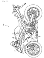
- a motorcycle 100 comprises an air intake port 1, through which an air is taken in, an air cleaner 5, an engine body 13, and a muffler 17.
- the air intake port 1 and the air cleaner 5 are connected to each other through an intake duct 3.
- the air cleaner 5 and combustion chambers 13c (see Fig. 2, not shown in Fig. 1) of the engine body 13 are connected to each other through intake passages 9.
- the combustion chambers 13c and the muffler 17 are connected to each other through an exhaust passage 15.
- Upstream injectors 7 are arranged inside the air cleaner 5 and downstream injectors 11 are arranged inside the intake passages 9.
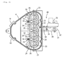
- the engine is a parallel 4-cylinder engine and the four intake passages 9 are provided along in a vehicle breadth direction (a front-back surface direction in Fig. 1).
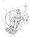
- the air cleaner 5 comprises a lower bowl-shaped casing 4 opened upward, and an upper bowl-shaped casing 2 opened downward.
- the upper casing 2 and the lower casing 4 are joined together in a state, in which mutual peripheral edges are butted against each other.
- an intake chamber 12 is compartmented inside the upper casing 2 and the lower casing 4.
- An element 8 is arranged inside the intake chamber 12 to remove dust and impurities contained in the air.
- the four intake passages 9 aligned in the vehicle breadth direction are formed in the engine.
- the respective intake passages 9 comprise a first funnel 24 fitted into the through-hole 22, a throttle body 26 fitted into the first funnel 24, a joint member 36 connected to a downstream end of the throttle body 26, and an intake port 13f connected to a downstream end of the joint member 36.
- the first funnel 24 is opened into the intake chamber 12.
- a throttle valve 28 is provided inside the throttle body 26.
- the intake port 13f is communicated to the combustion chamber 13c.
- an intake valve 13b driven by an intake cam 13a.
- an exhaust passage 15 (not shown in Fig. 2, see Fig. 1) is communicated to the combustion chamber 13c.
- an exhaust valve 13e driven by an exhaust cam 13d.
- a mount 26b, to which the downstream injector 11 is mounted, is formed on a portion of the throttle body 26 downstream of the throttle valve 28.
- the downstream injector 11 is mounted to the mount 26b and a nozzle 11 a of the downstream injector 11 is extended inside the intake passage 9. Accordingly, the downstream injector 11 jets a fuel downstream of the throttle valve 28.
- a separate chamber cover 14 is mounted to an inner surface of a rear portion of the upper casing 2.
- a separate chamber 16 is compartmented between the separate chamber cover 14 and the upper casing 2, and the upstream injectors 7 are arranged in the separate chamber 16.
- nozzles 7a of the upstream injectors 7 extend through the separate chamber cover 14 to extend to the intake chamber 12.
- the upstream injector 7 is arranged so as to jet a fuel inside the first funnel 24.
- An obliquely upwardly projecting support base 18 is formed on the bottom surface of the rear portion of the lower casing 4.
- the support base 18 mounts thereto support rods 19 extending in parallel to a direction, in which the first funnels 24 are opened.
- a support plate 20 extending in the vehicle breadth direction (a front-back surface direction in Fig. 2) is fixed to upper ends of the support rods 19.
- four second funnels 25 aligned in the vehicle breadth direction are fixed to the support plate 20.
- the second funnels 25 comprises a cylindrical-shaped body, of which an upper end is formed to be bell-mouth-shaped.
- the second funnels 25 are substantially the same in inside diameter as the first funnels 24.
- the second funnels 25 are substantially the same in outside diameter as the first funnels 24.
- the first funnels 24 and the second funnels 25 may be different in inside or outside diameter from each other.
- the second funnels 25 are arranged on extensions of the first funnels 24. That is, the second funnels 25 are arranged to be coaxial with the first funnels 24. The second funnels 25 are arranged in positions away from the first funnels 24, and clearances are defined between the upstream ends of the first funnels 24 and the downstream ends of the second funnels 25.
- Cylinders 23 made of aluminum are inserted inside the second funnels 25.
- the cylinders 23 are arranged to be coaxial with the first funnels 24 and the second funnels 25.
- the cylinders 23 have a length substantially equal to a distance between the upstream ends of the first funnels 24 and the downstream ends of the second funnels 25.
- the cylinders 23 are freely moved in an axial direction. Specifically, the cylinders 23 are moved between positions (see Fig. 2), in which lower ends thereof are fitted into the first funnels 24, and positions (see Fig. 3), in which the lower ends thereof are away from the first funnels 24.
- the cylinders 23 have an outside diameter substantially equal to an inside diameter of the second funnels 25. Therefore, no clearances are substantially formed between the cylinders 23 and the second funnels 25. Accordingly, while the cylinders 23 are freely moved axially, the cylinders 23 and the second funnels 25 are contiguous to each other.
- the cylinders 23 have an outside diameter substantially equal to an inside diameter of the second funnels 25. Therefore, when the cylinders 23 are fitted into the first funnels 24, the cylinders 23 are made contiguous to the first funnels 24. Irrespective of positions of the cylinders 23, the cylinders 23 are contiguous to the second funnels 25. Accordingly, when the cylinders 23 are fitted into the first funnels 24, the first funnels 24 and the second funnels 25 are made contiguous to each other through the cylinders 23, so that the intake passages 9 are lengthened in total length. In this manner, the cylinders 23 and the second funnels 25 make a part of the intake passages 9 in a state, in which the cylinders 23 are fitted into the first funnels 24.
- a state in which the cylinders 23 are away from the first funnels 24, the upper ends of the first funnels 24 serve as opened ends of the intake passages 9.
- the upper ends of the second funnels 25 serve as opened ends of the intake passages 9.
- a state in which the cylinders 23 are away from the first funnels 24, is referred to a short state
- a state in which the cylinders 23 are fitted into the first funnels 24, is referred to a long state.
- the second funnels 25 are positioned between the nozzles 7a of the upstream injectors 7 and the first funnels 24.
- the nozzles 7a are arranged obliquely upward from the upstream ends of the second funnels 25. More specifically, the nozzles 7a are arranged in positions distant a predetermined distance from the upstream ends of the second funnels 25 in an axial direction of the second funnels 25. Also, the nozzles 7a are arranged centrally in openings of the second funnels 25 as viewed in the axial direction of the second funnels 25. That is, the nozzles 7a jet a fuel toward centers of the second funnels 25 from positions away from the upstream ends of the second funnels 25.
- the cylinders 23 project obliquely upward from the second funnels 25 in the short state (see Fig. 3).
- the nozzles 7a are positioned obliquely upward from upper ends of the cylinders 23 in the short state. Accordingly, the nozzles 7a jet a fuel toward positions distant obliquely upwardly from the cylinders 23 and the second funnels 25 at all times.
- the nozzles 7a jet a fuel in a manner to have the same spreading upstream of the upstream ends of the cylinders 23.
- Such configuration of jetting can be readily realized by appropriately setting a diameter of the nozzles 7a, a distance of the nozzles 7a from the cylinders 23, a jetting direction of the nozzles 7a, a jet velocity, etc.
- a connection rod 27 extending in the vehicle breadth direction is mounted to the cylinders 23.
- the connection rod 27 extends through the respective cylinders 23 to connect the four cylinders 23 together.
- slots 29 extending in the axial direction of the second funnels 25 are formed on both sides of the second funnels 25 in the vehicle breadth direction.
- the connection rod 27 is arranged in the slots 29.
- connection rod 27 is supported rotatably on one end of a lever 30 extending in a longitudinal direction (a left and right direction in Fig. 2).
- a cam bearing roller 31 projecting laterally is provided on the other end of the lever 30.
- a cam 32 and a motor 33 for rotation of the cam 32 are arranged on the other end side of the lever 30.
- the cam 32 is arranged above the cam bearing roller 31 to contact with the cam bearing roller 31.
- a middle portion of the lever 30 is supported rotatably on a support shaft 34, and a spring 35 is mounted on a rear side of the support shaft 34 to pull the other end of the lever 30 upward.
- a passage length varying mechanism 40 that varies a length (an intake passage length) of the intake passages 9 is formed by the cylinders 23, the second funnels 25, and the moving mechanism that moves the cylinders 23.
- reference numeral 60 denotes a controller that controls injection of the upstream injectors 7 and the downstream injectors 11 and the passage length varying mechanism 40.
- An air introduced from the introduction port 10 of the air cleaner 5 is purified by the element 8 and then sucked into the intake passages 9.
- an air is sucked from the second funnels 25.
- an air is sucked from the first funnels 24. More specifically, a part of the air passes through the second funnels 25 and is then sucked into the first funnels 24, and the remainder of the air is sucked into the first funnels 24 through clearances between the first funnels 24 and the second funnels 25.
- the intake valves 13b are opened by the intake cams 13a and a fuel is jetted from one of the upstream injectors 7 and the downstream injectors 11.
- impulse waves are generated upstream from the vicinity of the intake ports 13f.
- an air and a fuel begin to flow into the combustion chambers 13c, so that the neighborhood of the intake ports 13f is put in a state of negative pressure and pulsation waves being compressional waves of an air are propagated upstream from downstream in the intake passages 9.
- the impulse waves arrive at upstream ends of the intake passages 9 to be propagated into the intake chamber 12.
- the pulsation waves arrive at the upstream ends of the intake passages 9 later than the impulse waves. Since the upstream ends of the intake passages 9 are opened to the intake chamber 12, directions, in which the pulsation waves are propagated, are reversed at the upstream ends of the intake passages 9.
- the pulsation waves are propagated downstream from upstream in the intake passages 9.
- An improvement in volumetric efficiency can be achieved by expediting inflow of an air and a fuel into the combustion chambers 13c by the use of those pulsation waves, which are reversed in directions of propagation. That is, torque of the engine can be increased by making the pulsation waves in synchronism with timing of intake.
- a torque characteristic curve of the engine makes a generally convex curve including mountains and valleys as in a curve S shown in Fig. 5(b) and having a maximum value at a predetermined engine speed.
- the curve S indicates torque characteristics in the case where the intake passages 9 are fixed in the short state and a fuel is injected only from the downstream injectors 11.
- the upstream injectors 7 are provided in positions relatively distant from the combustion chambers 13c, time elapsed until a fuel injected from the upstream injectors 7 arrives at the combustion chambers 13c becomes relatively long. Therefore, atomization of a fuel is expedited. Also, time for cooling of an air effected by atomization of a fuel becomes long. Accordingly, the upstream injectors 7 make it possible to increase an air density, thus enabling enhancing the volumetric efficiency of the engine.
- a period of pulsation waves depends on the acoustic velocity of an air and the acoustic velocity of an air depends on an air temperature. Accordingly, when an air temperature is decreased by injection of an fuel, the acoustic velocity is correspondingly decreased and pulsation waves are varied in period. Therefore, it can be said that the upstream injectors 7 function to increase an air density and to vary pulsation waves in period.
- a curve T indicates a torque characteristic curve in the case where the upstream injectors 7 are varied in ratio of injection so as to fill the torque valleys in the curve S while fixing the intake passages 9 in the short state.
- an alternate long and short dash line in Fig. 5(a) indicates the ratio of injection of the upstream injectors 7.
- the torque valleys in the torque characteristic curve S can be apparently filled by having the upstream injectors 7 appropriately performing injection.
- the curve T is actually only a result of moving the curve S to a side of low rotating speed and torque is not sharply increased as compared with the curve S. It is assumed that the reason for this is that the effect produced by the upstream injectors 7 to vary pulsation waves in period exceeds the effect of increasing the air density with the result that an increase in volumetric efficiency due to an increase in air density is not adequately achieved.
- the period of pulsation waves can be controlled by means, which is separate from the upstream injectors 7. That is, pulsation waves can be adjusted in period by switching the intake passages 9 between the short state and the long state. Accordingly, the torque valleys in the torque characteristic curve can be filled notwithstanding fuel injection by the upstream injectors 7.
- the torque valleys in the torque characteristic curve are filled by varying the intake passage length.
- a curve U in Fig. 5(b) is a torque characteristic curve of the engine according to the embodiment. According to the embodiment, torque can be sharply increased.
- the ratio of injection of the upstream injectors 7 in the embodiment is 100 % over a zone of rotating speed in a wide range. Thereby, it is possible to make a maximum use of the effect of an increase in air density, produced by the upstream injectors 7.
- a curve in Fig. 5(c) indicates changes in a length of the intake passages 9 relative to engine speed.
- the intake passages 9 are varied in length and when the intake passages 9 are varied in length, the ratio of injection of the upstream injectors 7 is made constant.
- the ratio of fuel injection of the upstream injectors 7 is constant before and after a change in torque characteristics.
- the ratio of injection of the upstream injectors 7 is made smaller than the ratio of injection of the downstream injectors 11, and when an air flow rate for the combustion chambers 13c becomes equal to or larger than a predetermined air flow rate, the ratio of injection of the upstream injectors 7 is preferably made a predetermined value larger than the ratio of injection of the downstream injectors 11. According to the embodiment, such control is exercised.
- the upstream injectors 7, which jet a fuel on upstream sides of the upstream ends of the intake passages 9, and the control mechanism, which varies the torque characteristics so as to eliminate the torque valleys in the torque characteristic curve, are combined, it is possible to have the upstream injectors 7 demonstrating the effect of an increase in volumetric efficiency to the maximum, thus enabling a great improvement in engine performance.
- the passage length varying mechanism 40 which varies a length of the intake passages 9, is used as a control mechanism, which varies the torque characteristics.
- the torque characteristics vary according to changes in intake passage length and also according to fuel injection from the upstream injectors 7. However, that rate, at which the torque characteristics vary due to changes in intake passage length, is larger than that rate, at which the torque characteristics vary due to fuel injection from the upstream injectors 7. Accordingly, it is possible according to the embodiment to effectively restrict the torque valleys.
- the passage length varying mechanism 40 has the motor 33 moving the cylinders 23. Accordingly, it is possible to rapidly vary a length of the intake passages 9 to rapidly vary the torque characteristics.
- the cylinders 23 are formed from aluminum to be made lightweight. Therefore, it is possible to readily and rapidly vary the intake passage length.
- a material for the cylinders 23 is not limited to aluminum.
- the cylinders 23 can be of course formed from a material having a large specific gravity.
- the cylinders 23 are moved in the second funnels 25 whereby the first funnels 24 and the second funnels 25 made contiguous or discontiguous to each other, thus varying the intake passage length. Therefore, the intake passage length varies in large degree. Accordingly, it is possible to greatly vary the engine in torque characteristics.
- the torque characteristics are controlled on a side of an intake system of the engine. That is, a phase of pressure waves generated in the intake passages 9 and the timing of intake of the combustion chambers 13c are made in synchronism with each other by varying the intake passage length. Accordingly, it is possible to further directly restrict generation of the torque valleys attributable to fuel injection from the upstream injectors 7.
- the upstream injectors 7 jet a fuel on upstream sides of the upstream ends of the cylinders 23 when the cylinders 23 are fitted into the first funnels 24 to put the intake passages 9 in the long state. Also, the upstream injectors 7 jet a fuel on upstream sides of the upstream ends of the cylinders 23 even when the cylinders 23 get out from the first funnels 24 and the intake passages 9 are put in the short state. Accordingly, it is possible to expedite atomization of a fuel to achieve a further increase in air density.
- the upstream injectors 7 jet a fuel in a manner to have the same spreading upstream of the upstream ends of the cylinders 23, so that it is possible to expedite atomization of a fuel to achieve a further increase in air density.
- a part of the passage length varying mechanism 40 that is, the second funnels 25, the cylinders 23, etc. is arranged inside the intake chamber 12. Therefore, it is possible to achieve making the passage length varying mechanism 40 small in size. As a result, it is possible to produce the effect of increasing freedom in layout of the vehicle, or the like.
- the upstream injectors 7 are not made ON/OFF when the intake passage length is varied. Accordingly, control in a transient state is easy.
- the ratio of injection of the upstream injectors 7 is constant before and after a change in intake passage length. Accordingly, control in a transient state can be further exercised.
- the ratio of injection of the upstream injectors 7 is constant over a zone of rotating speed in a wide range. Therefore, it is not necessary to finely control the upstream injectors 7 according to a change in rotating speed. Accordingly, this is especially preferable in a vehicle, for example, a motorcycle, or the like, which is operated in a zone of rotating speed in a wide range and in which a change in rotating speed is large.
- "motorcycle” referred to in the specification of the present application includes a scooter, etc. in addition to a so-called motorbike.
- the engine in the embodiment comprises the upstream injectors 7 and the downstream injectors 11 and is a so-called twin-injector type engine.
- the engine according to the invention may comprise only the upstream injectors 7.
- the upstream injectors 7 are arranged inside the air cleaner 5. However, the upstream injectors 7 may be arranged outside the air cleaner 5 as far as a fuel is jetted inside the intake chamber 12.
- a control device that controls the upstream injectors 7 and the downstream injectors 11 may be the same as, or different from a control device that controls the passage length varying mechanism 40.
- control mechanism that varies the torque characteristic curve so as to restrict the torque valleys is not limited to the passage length varying mechanism 40 in the embodiment. Subsequently, an explanation will be given to a further embodiment, in which other control mechanism than the passage length varying mechanism 40 is provided.
- an intake passage length is varied by the motor 33.
- an intake passage length is varied by a cylinder that operates under a negative intake pressure.
- a separate chamber 16 compartmented from an intake chamber 12 is formed inside an air cleaner 5 and upstream injectors 7 are arranged in the separate chamber 16.
- first funnels 114 are connected to upstream ends of throttle bodies 26.
- the first four funnels 114 aligned in a vehicle breadth direction are fixed to a common stationary plate 115.
- Second funnels 116 are arranged on opened sides of the first funnels 114 to be able to contact with and separate from the first funnels 114.
- the four second funnels 116 aligned in the vehicle breadth direction are supported integrally by a movable plate 117.
- the movable plate 117 is formed with circular holes 117a, which permit the second funnels 116 to be inserted therethrough.
- the second funnels 116 are fitted slidably into the circular holes 117a.
- Stoppers 118 are fixed to outer peripheral surfaces of the second funnels 116, and springs 119 are arranged between the stoppers 118 and the movable plate 117. Thereby, the second funnels 116 are constantly biased toward the first funnels 114 (downward in the figure) by the springs 119.
- Steps 116a are formed on the outer peripheral surfaces of the second funnels 116. As shown in Fig. 7, when the second funnels 116 are away from the first funnels 114, the second funnels 116 are stationary in positions, in which the steps 116a abut against the movable plate 117. Accordingly, in a state shown in Fig. 7, the second funnels 116 can be moved integrally together with the movable plate 117.
- a cylinder 120 as an actuator is mounted to a central portion of the stationary plate 115.
- a guide bar 121 extending vertically from the stationary plate 115 is mounted to one end of the stationary plate 115.
- the guide bar 121 extends slidably through a circular hole of the movable plate 117.
- a piston 123 is fitted slidably in parallel to an axial direction of the second funnels 116 inside a body 122 of the cylinder 120.
- a chambers S1 (see Fig. 8) and a chamber S2, which are compartmented by the piston 123, are formed inside the cylinder body 122.
- Ports 124, 125 opened to the chambers S1, S2 are formed in the cylinder body 122.
- the ports 124, 125, respectively, are connected to a solenoid type switching valve 128 through pipes 126, 127.
- the switching valve 128 is connected to an intake system of the engine body 13 through a pipe 129.
- a rod 131 is extended upward from the piston 123 of the cylinder 120.
- a central portion of the movable plate 117 is fixed to an end of the rod 131 by a nut 132.
- the cylinder 120 which operates under the negative intake pressure generated in the engine body 13, is adopted as an actuator to drive the movable plate 117, moving motions of the second funnels 116 are high in response. Accordingly, it is possible to rapidly vary the torque characteristics.
- a third embodiment comprises a valve operating device and varies timing of opening and closing of, or time of opening and closing of intake valves or exhaust valves to vary the torque characteristic curve.
- valve operating device in an intake system.
- valve operating device in an exhaust system.
- any throttle valve is not provided in an intake passage. That is, the embodiment comprises a so-called non-throttle valve type engine.
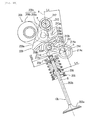
- an intake valve 13b comprises a valve shaft 203b, a valve head 203a mounted to a tip end of the valve shaft 203b, and a retainer 204 fixed to a root portion (an upper end) of the valve shaft 203b.
- a valve spring 206 is arranged between the retainer 204 and a spring seat 205 of a cylinder head 202. Thereby, the intake valve 13b is constantly biased in a closing direction by the valve spring 206.
- a valve operating device 207 is arranged above the intake valve 13b.
- the valve operating device 207 comprises a swing member 209, an intermediate rocker 210, and a rocker arm 211.
- the valve operating device 207 causes an intake cam shaft 208 to swing the swing member 209, and causes the swing member 209 to swing the rocker arm 211 through the intermediate rocker 210, and the intake valve 13b is axially retreated by swinging of the rocker arm 211, thus opening and closing an intake opening 202b.
- the intake cam shaft 208 is formed with a cam nose 208c.
- the cam nose 208c comprises a base circular portion 208a having a constant outside diameter, and a lift portion 208b having a predetermined cam profile.
- the swing member 209 comprises a pair of swing arm portions 209a arranged in parallel to the intake cam shaft 208 and supported on a swing shaft 212 to be able to swing, swing cam surfaces 209b formed so as to connect tip ends (lower ends) of the swing arm portions 209a together, a roller shaft 209c arranged midway the swing arm portions 209a in parallel to the swing shaft 212 and extending through the swing arm portions 209a, and a swing roller 209d supported rotatably on the roller shaft 209c.
- the swing roller 209d contacts with the cam nose 208c at all times.
- the swing shaft 212 extends through a base (an upper end) of the swing arm portions 209a to be able to swing.
- a balance spring 213 composed of a coil spring is mounted to the swing shaft 212.
- One end 213a of the balance spring 213 is latched on the swing arm portions 209a and the other end 213b is latched on the cylinder head 202.
- the balance spring 213 biases the swing member 209 so that the swing roller 209d abuts against the cam nose 208c, whereby application of a weight of the swing member 209 on the valve spring 206 is avoided.
- the swing cam surfaces 209b comprise a curved surface, which a base circular portion 209e and a lift portion 209f are made contiguous to each other to define.
- the base circular portion 209e is arcuate about a swing center a, which is an axis of the swing shaft 212, to have a radius R1. Therefore, while the base circular portions 209e contact with the swing roller 209d, the intake valve 13b is present in a fully closed position and not lifted even when the swing member 209 is increased in swing angle.
- the lift portions 209f greatly lift the intake valve 13b as a portion near a top of the lift portion 208b pushes the swing roller 209d, that is, the swing member 209 is increased in swing angle.
- the lift portion 208b comprises a ramp section, in which speed is constant, an acceleration section, in which speed is varied, and a lift section, in which speed is substantially constant.
- the rocker arm 211 comprises a cylindrical-shaped base 211 c and an arm portion 211 d extending forward (toward the intake valve) from the base 211 c.
- the base 211 c is supported on a rocker shaft 214, which is arranged in parallel to the intake cam shaft 208, to able to swing.
- a valve pushing surface 211 a is formed on a lower portion of a tip end of the arm portion 211 d.
- the valve pushing surface 211 a pushes a shim 203c mounted to an upper end of the valve shaft 203b.
- a rocker pushing surface 211 b is formed on an upper edge of the arm portion 211 d.
- the rocker pushing surface 211 b contacts with a rocker pin 210a of the intermediate rocker 210 to be pushed by the rocker pin 210a.
- the rocker pushing surface 211 b is formed to have an arc of a radius R2 about a swing center a of the swing member 209 in a fully closed position of the valve.
- the rocker shaft 214 is provided with a motor 250.
- a controller 251 controls the motor 250 whereby a rotationally angular position of the rocker shaft 214 is freely adjusted.
- An eccentric pin portion 214a is provided midway the rocker shaft 214 to be made radially outwardly eccentric from an axis b.
- a recess 210c is formed on a base end of an intermediate arm portion 210b of the intermediate rocker 210, the recess 210c being latched on the eccentric pin portion 214a.
- the intermediate rocker 210 comprises the intermediate arm portion 210b and the rocker pin 210a connected to a tip end of the intermediate arm portion 210b to extend in a direction along the cam shaft.
- a rocker roller 210d is supported rotatably on the rocker pin 210a. The rocker roller 210d contacts with the swing cam surfaces 209b of the swing member 209, and the rocker pin 210a contacts with the rocker pushing surface 211 b of the rocker arm 211.
- a straight line A connects between the swing center a of the swing member 209 and a point of contact c of the swing cam surfaces 209b and the intermediate rocker roller 210d.
- a rocker lever ratio is represented by Lv/Lc where Lc indicates a distance from the straight line A to a swing center b of the rocker arm 211 and Lv indicates a distance from a valve axis B to the swing center b of the rocker arm 211. The shorter a period of time of valve opening, the larger the lever ratio.
- curves C1' to C3' in Fig. 11 indicate lift curves of a comparative example in the case where the rocker lever ratio is constant. That is, a device of the comparative example is set so as to have the same characteristics as that of the lift curve in the state of large opening degree in the embodiment, and a comparison is made for changes in lift in the case where shift is made therefrom to the state of small opening degree. As apparent from the figure, with the device of the comparative example, in which the rocker lever ratio is constant, lift shifts from the curve C3' to the curve C1' via the curve C2' to fall greatly.
- valve operating device 207 is provided on an intake side to vary timing of opening and closing of and a period of time of opening and closing of the intake valve 13b.
- valve operating device 207 may be provided on an exhaust side to vary timing of opening and closing of and a period of time of opening and closing of the exhaust valve. Even in this case, it is possible to vary the torque characteristics so as to restrict the torque valleys in the torque characteristic curve.
- the valve operating device 207 serves to vary both timing of opening and closing of and a period of time of opening and closing of the valve. However, the valve operating device 207 may vary either of timing of opening and closing of and a period of time of opening and closing of the valve.
- the valve operating device may be of an electromagnetic valve type or a hydraulic valve type.
- the valve operating device is not limited to such specific type.
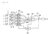
- a fourth embodiment comprises a mechanism that varies a length of an exhaust passage, as a control mechanism that varies the torque characteristics.
- the control mechanism according to the embodiment exercises control to make a phase of pressure waves generated in the exhaust passage and timing of exhaust of a combustion chamber in synchronism with each other.
- the engine according to the embodiment comprises a 4-cylinder four valve engine including two intake valves 13b and two exhaust valves 13e every cylinder.
- An exhaust device 308 of the engine comprises a right manifold 309a that combines exhaust ports of cylinders on a left end and a right end, a left manifold 309b that combines exhaust ports of two central cylinders, and a junction pipe 309 that combines the manifolds 309a, 309b into one.
- An exhaust control valve 310 is arranged on the communicating pipe 309c to open and close the communicating pipe 309c.
- a substantially exhaust passage length of the exhaust device 308 is varied by opening and closing of the exhaust control valve 310. That is, the passage length of the exhaust passage is put in the long state when the exhaust control valve 310 is closed, and put in the short state when the exhaust control valve 310 is opened.
- the exhaust control valve 310 is controlled by a controller 305.
- the exhaust passage length is varied in this manner whereby pulsation waves generated in the exhaust passage are varied in period. Accordingly, the exhaust passage length is caused to vary, thereby enabling varying the torque characteristics.
- the same effect as that in the first embodiment can be also produced in the embodiment.
- a mechanism that varies an exhaust passage length is not limited to the mechanism. It is of course possible to use other mechanisms as a control mechanism that varies the torque characteristics.
- the fifth embodiment comprises, as a control mechanism that varies the torque characteristics, a reflecting plate provided in an exhaust passage to reflect pressure waves. That is, according to the embodiment, a part of pressure waves generated in the exhaust passage is reflected by the reflecting plate, and thus pressure waves reflected at an opened end of the exhaust passage and pressure waves (reflected waves) reflected by the reflecting plate are caused to interfere with each other. The interference damps the pressure waves and varies the torque characteristics.
- the engine according to the embodiment comprises a butterfly-shaped reflecting plate 311 provided in a junction pipe (simply referred below to as exhaust pipe) 309.
- a junction pipe (simply referred below to as exhaust pipe) 309.
- the reflecting plate 311 may be of course provided on an engine without the exhaust control valve 310.
- the reflecting plate 311 comprises a spindle fixed to the exhaust pipe 309, and a disk supported rotatably on the spindle.
- the disk is supported to be concentric with an inner surface of an exhaust pipe 311.
- the spindle When the spindle is rotated, the disk rotates about the spindle, so that the reflecting plate 311 is varied in cross sectional area.
- An area of the disk is set to about a half of the cross sectional area of the exhaust pipe 311, and when the reflecting plate 311 is closed by the spindle, a half of the cross sectional area of the exhaust pipe 309 is closed and the reflecting surface becomes maximum.
- a control mechanism that makes use of pulsation waves generated in an intake passage or an exhaust passage to vary the torque characteristics is not limited to the mechanisms of the respective embodiments.
- the control mechanism may be one that varies an intake passage or an exhaust passage in flow passage area. It is possible to make use of an optional mechanism that varies an intake passage or an exhaust passage in flow passage area, as the control mechanism.
- Fig. 14 is a view schematically showing a mechanism that varies an exhaust passage in flow passage area. With the mechanism, an expansion passage 401 expanding and contracting radially is formed midway an exhaust passage 15. A drive mechanism 400 expands and contracts the expansion passage 401.
- the torque characteristics can be varied also by varying the flow passage area. Accordingly, it is possible to produce the same effect as that in the first embodiment.
- control mechanism may be one that varies an intake passage in temperature or an exhaust passage in temperature. Also, since the period of pulsation waves varies according to an air pressure, the control mechanism may be one that varies an intake passage in pressure or an exhaust passage in pressure.
- an engine comprising an engine body having a combustion chamber, an intake chamber having an introduction port, through which an air is introduced, an intake passage, which includes an opening opened into the intake chamber and through which the air in the intake chamber is led from the opening to the combustion chamber, an injector that jets a fuel between the introduction port and the opening, an exhaust passage, through which combustion gases are led from the combustion chamber, and a control mechanism that makes use of pressure waves generated in at least one of the intake passage and the exhaust passage to vary torque characteristics so as to eliminate valleys in a torque characteristic curve indicating a change in torque relative to a change in engine speed.
- control mechanism varies the torque characteristics at a larger rate than that, at which the torque characteristics varies due to fuel injection of the injector.
- the description further discloses an embodiment of an engine comprising an engine body having a combustion chamber, an intake chamber having an introduction port, through which an air is introduced, an intake passage, which includes an opening opened into the intake chamber and through which the air in the intake chamber is led from the opening to the combustion chamber, an injector that jets a fuel between the introduction port and the opening, and a control mechanism that exercises control to synchronize phase of pressure waves generated in the intake passage and timing of intake of the combustion chamber with each other.
- the description above further provides an embodiment of the engine comprising an engine body having a combustion chamber, an intake chamber having an introduction port, through which an air is introduced, an intake passage, which includes an opening opened into the intake chamber and through which the air in the intake chamber is led from the opening to the combustion chamber, an injector that jets a fuel between the introduction port and the opening, and a control mechanism that exercises control to synchronize phase of pressure waves generated in the exhaust passage and timing of exhaust of the combustion chamber with each other.
- an air flowing through the intake passage is evaporated and cooled by a fuel, which is jetted from the injector, over a relatively long period of time. Therefore, the air density is increased and the volumetric efficiency of the engine is enhanced.
- the control mechanism adjusts the torque characteristics so as to eliminate valleys in a torque characteristic curve. Therefore, although injection of a fuel from the injector varies the period of pulsation waves in the intake passage, a decrease in torque is restricted. Accordingly, it is possible to demonstrate the effect of an increase in volumetric efficiency, produced by the injector, to the maximum, and so a great improvement in engine performance is achieved.
- the control mechanism comprises a passage length varying mechanism that varies a length of the intake passage.
- the passage length varying mechanism may comprise a cylindrical-shaped body having an upstream-side opening and a downstream-side opening, and a drive mechanism that relatively moves the cylindrical-shaped body and the intake passage in a direction along the passage, and the injector may jet a fuel on an upstream side of the upstream-side opening disposed when the cylindrical-shaped body is moved to a downstream-most side.
- the injector further may jet a fuel on an upstream side of the upstream-side opening disposed when the cylindrical-shaped body is moved to an upstream-most side.
- the intake passage may further be fixed to the engine body, and the drive mechanism may move the cylindrical-shaped body. Additionally, the injector may jet a fuel so as to have the same spreading on the upstream side of the upstream-side opening.
- the passage length varying mechanism comprises a cylindrical-shaped body having an upstream-side opening and a downstream-side opening, and a drive mechanism that relatively moves the cylindrical-shaped body and the intake passage in a direction along the passage, and the drive mechanism relatively moves the cylindrical-shaped body and the intake passage between a first state, in which the cylindrical-shaped body and the intake passage contact with each other, and a second state, in which the cylindrical-shaped body and the intake passage separate from each other.
- an intake port is formed on the combustion chamber, and the engine further comprises an intake valve that opens and closes the intake port, and a valve opening and closing mechanism that drives the intake valve, and wherein the control mechanism comprises an intake timing varying mechanism that varies timing of opening and closing of and a period of timing of opening of the intake valve caused by the valve opening and closing mechanism.
- control mechanism comprises a passage length varying mechanism that varies a length of the exhaust passage.
- an exhaust port is formed on the combustion chamber, and the engine further comprises an exhaust valve that opens and closes the exhaust port, and a valve opening and closing mechanism that drives the exhaust valve, and wherein the control mechanism comprises an exhaust timing varying mechanism that varies timing of opening and closing of and a period of timing of opening of the exhaust valve caused by the valve opening and closing mechanism.
- the engine further comprises a reflecting member that reflects pressure waves
- the control mechanism comprises a reflection area varying mechanism that varies an area of reflection by the reflecting member.
- the engine may further comprise a downstream injector that jets a fuel between the throttle valve and the combustion chamber, and an injection control device that controls the injector and the downstream injector, and wherein the injection control device continues fuel injection from the injector before and after the control mechanism exercises the control.
- the engine may further comprise a downstream injector that jets a fuel between the throttle valve and the combustion chamber, and an injection control device that controls the injector and the downstream injector, and wherein the injection control device maintains a ratio of injection of the injector and the downstream injector before and after the control mechanism exercises the control.
- the engine may further comprise a downstream injector that jets a fuel between the throttle valve and the combustion chamber, and an injection control device that controls the injector and the downstream injector, and wherein the injection control device makes a ratio of injection of the injector smaller than a ratio of injection of the downstream injector when a flow rate of an air to the combustion chamber is less than a predetermined amount, and makes a ratio of injection of the injector a constant ratio of injection, which is smaller than a ratio of injection of the downstream injector.
- At least a part of the control mechanism is arranged in the intake chamber.
- a vehicle comprises the engine according to any one of the above embodiments.
- an injector In order to greatly improve the engine performance by demonstrating the effect of an increase in volumetric efficiency, produced by an injector, to the maximum, the description discloses a preferred embodiment according to which there are provided in an air cleaner 5 first funnels 24 connected to upstream ends of throttle bodies 26 and opened to an intake chamber 12, second funnels 25 arranged coaxial with the first funnels 24 and separated from the first funnels 24, and cylinders 23 inserted inside the second funnels 25.
- An engine comprises a passage length varying mechanism 40 that moves the cylinders 23 to thereby vary intake passages 9 in length.
- the engine comprises upstream injectors 7 that jet a fuel from upstream sides of the cylinders 23.
- a fuel feed device which comprises an intake chamber having an introduction port, through which an air is introduced, an intake passage, which includes an opening opened into the intake chamber and through which an air in the intake chamber is led from the opening to an engine, an injector that jets a fuel toward the opening from between the introduction port and the opening in the intake chamber, and a tubular jet protection member arranged between the injector and the opening in the intake chamber to permit a fuel jetted from the injector to pass therethrough toward the opening.
Landscapes
- Engineering & Computer Science (AREA)
- Chemical & Material Sciences (AREA)
- Combustion & Propulsion (AREA)
- Mechanical Engineering (AREA)
- General Engineering & Computer Science (AREA)
- Health & Medical Sciences (AREA)
- Biomedical Technology (AREA)
- Physics & Mathematics (AREA)
- Geometry (AREA)
- Characterised By The Charging Evacuation (AREA)
- Electrical Control Of Air Or Fuel Supplied To Internal-Combustion Engine (AREA)
- Output Control And Ontrol Of Special Type Engine (AREA)
Applications Claiming Priority (1)
| Application Number | Priority Date | Filing Date | Title |
|---|---|---|---|
| JP2004320253A JP2006132371A (ja) | 2004-11-04 | 2004-11-04 | エンジン及びそれを備えた車両 |
Publications (3)
| Publication Number | Publication Date |
|---|---|
| EP1655464A2 true EP1655464A2 (de) | 2006-05-10 |
| EP1655464A3 EP1655464A3 (de) | 2011-09-14 |
| EP1655464B1 EP1655464B1 (de) | 2013-01-09 |
Family
ID=35501188
Family Applications (1)
| Application Number | Title | Priority Date | Filing Date |
|---|---|---|---|
| EP05024088A Expired - Lifetime EP1655464B1 (de) | 2004-11-04 | 2005-11-04 | Motor |
Country Status (2)
| Country | Link |
|---|---|
| EP (1) | EP1655464B1 (de) |
| JP (1) | JP2006132371A (de) |
Cited By (9)
| Publication number | Priority date | Publication date | Assignee | Title |
|---|---|---|---|---|
| WO2008095859A1 (en) * | 2007-02-08 | 2008-08-14 | Castiglioni, Claudio | Intake system for motorcycle engine |
| EP2022974A2 (de) | 2007-07-24 | 2009-02-11 | Yamaha Hatsudoki Kabushiki Kaisha | Fahrzeug |
| CN101187332B (zh) * | 2006-11-24 | 2010-06-02 | 雅马哈发动机株式会社 | 车辆 |
| CN101187331B (zh) * | 2006-11-24 | 2010-10-13 | 雅马哈发动机株式会社 | 车辆 |
| EP2017459A3 (de) * | 2007-07-20 | 2010-11-03 | Yamaha Hatsudoki Kabushiki Kaisha | Fahrzeug |
| EP2003306A3 (de) * | 2007-06-15 | 2013-04-10 | Keihin Corporation | Ansaugsteuerungssystem für einen Motor |
| EP2003307A3 (de) * | 2007-06-15 | 2013-04-17 | Keihin Corporation | Ventilbetriebssystem und Ansaugsteuerungssystem für einen Motor |
| IT201600111203A1 (it) * | 2016-11-04 | 2018-05-04 | Piaggio & C Spa | Motore endotermico con sistema di aspirazione migliorato e relativo motoveicolo |
| WO2018083651A1 (en) * | 2016-11-04 | 2018-05-11 | Piaggio & C. S.P.A. | Internal combustion engine with an improved intake system and motorvehicle thereof |
Families Citing this family (7)
| Publication number | Priority date | Publication date | Assignee | Title |
|---|---|---|---|---|
| JP4842066B2 (ja) * | 2006-04-14 | 2011-12-21 | ヤマハ発動機株式会社 | 車両 |
| JP4698544B2 (ja) * | 2006-09-26 | 2011-06-08 | 本田技研工業株式会社 | 内燃機関 |
| DE102007008545B4 (de) * | 2007-02-21 | 2009-04-23 | Kreyer, Norbert, Dipl.-Ing. | Saugrohranordnung für Brennkraftmaschinen |
| JP4932747B2 (ja) * | 2008-01-15 | 2012-05-16 | ヤマハ発動機株式会社 | 可変動弁装置 |
| JP5198984B2 (ja) * | 2008-09-05 | 2013-05-15 | ヤマハ発動機株式会社 | 車両 |
| JP5407992B2 (ja) * | 2010-03-31 | 2014-02-05 | マツダ株式会社 | 多気筒エンジンの排気装置 |
| JP5723201B2 (ja) * | 2011-04-18 | 2015-05-27 | 川崎重工業株式会社 | 燃料噴射制御装置 |
Citations (5)
| Publication number | Priority date | Publication date | Assignee | Title |
|---|---|---|---|---|
| JPH10196494A (ja) | 1997-01-14 | 1998-07-28 | Honda Motor Co Ltd | 燃料噴射装置 |
| US6202627B1 (en) | 1998-08-05 | 2001-03-20 | Honda Giken Kogyo Kabushiki Kaisha | V-type multi-cylinder internal combustion engine |
| EP1293653A1 (de) | 2001-09-14 | 2003-03-19 | Ducati Motor Holding S.p.A. | Vorrichtung zum Mischen von Luft und Brennstoff für eine Brennkraftmaschine |
| EP1304461A1 (de) | 2001-10-17 | 2003-04-23 | Hitachi, Ltd. | Ansaugmodul für eine Brennkraftmaschine, und mehrere und unabhängige Einlasskanäle |
| JP2004100632A (ja) | 2002-09-11 | 2004-04-02 | Honda Motor Co Ltd | エンジン用燃料噴射装置 |
-
2004
- 2004-11-04 JP JP2004320253A patent/JP2006132371A/ja not_active Withdrawn
-
2005
- 2005-11-04 EP EP05024088A patent/EP1655464B1/de not_active Expired - Lifetime
Patent Citations (5)
| Publication number | Priority date | Publication date | Assignee | Title |
|---|---|---|---|---|
| JPH10196494A (ja) | 1997-01-14 | 1998-07-28 | Honda Motor Co Ltd | 燃料噴射装置 |
| US6202627B1 (en) | 1998-08-05 | 2001-03-20 | Honda Giken Kogyo Kabushiki Kaisha | V-type multi-cylinder internal combustion engine |
| EP1293653A1 (de) | 2001-09-14 | 2003-03-19 | Ducati Motor Holding S.p.A. | Vorrichtung zum Mischen von Luft und Brennstoff für eine Brennkraftmaschine |
| EP1304461A1 (de) | 2001-10-17 | 2003-04-23 | Hitachi, Ltd. | Ansaugmodul für eine Brennkraftmaschine, und mehrere und unabhängige Einlasskanäle |
| JP2004100632A (ja) | 2002-09-11 | 2004-04-02 | Honda Motor Co Ltd | エンジン用燃料噴射装置 |
Cited By (13)
| Publication number | Priority date | Publication date | Assignee | Title |
|---|---|---|---|---|
| EP1925809A3 (de) * | 2006-11-24 | 2014-01-08 | Yamaha Hatsudoki Kabushiki Kaisha | Fahrzeug |
| CN101187332B (zh) * | 2006-11-24 | 2010-06-02 | 雅马哈发动机株式会社 | 车辆 |
| CN101187331B (zh) * | 2006-11-24 | 2010-10-13 | 雅马哈发动机株式会社 | 车辆 |
| EP1925810A3 (de) * | 2006-11-24 | 2014-01-01 | Yamaha Hatsudoki Kabushiki Kaisha | Fahrzeug |
| WO2008095859A1 (en) * | 2007-02-08 | 2008-08-14 | Castiglioni, Claudio | Intake system for motorcycle engine |
| EP2003306A3 (de) * | 2007-06-15 | 2013-04-10 | Keihin Corporation | Ansaugsteuerungssystem für einen Motor |
| EP2003307A3 (de) * | 2007-06-15 | 2013-04-17 | Keihin Corporation | Ventilbetriebssystem und Ansaugsteuerungssystem für einen Motor |
| EP2017459A3 (de) * | 2007-07-20 | 2010-11-03 | Yamaha Hatsudoki Kabushiki Kaisha | Fahrzeug |
| EP2022974A2 (de) | 2007-07-24 | 2009-02-11 | Yamaha Hatsudoki Kabushiki Kaisha | Fahrzeug |
| EP2022974A3 (de) * | 2007-07-24 | 2010-10-27 | Yamaha Hatsudoki Kabushiki Kaisha | Fahrzeug |
| IT201600111203A1 (it) * | 2016-11-04 | 2018-05-04 | Piaggio & C Spa | Motore endotermico con sistema di aspirazione migliorato e relativo motoveicolo |
| WO2018083651A1 (en) * | 2016-11-04 | 2018-05-11 | Piaggio & C. S.P.A. | Internal combustion engine with an improved intake system and motorvehicle thereof |
| US10995708B2 (en) | 2016-11-04 | 2021-05-04 | Piaggio & C. S.P.A. | Internal combustion engine with an improved intake system and motorvehicle thereof |
Also Published As
| Publication number | Publication date |
|---|---|
| EP1655464A3 (de) | 2011-09-14 |
| EP1655464B1 (de) | 2013-01-09 |
| JP2006132371A (ja) | 2006-05-25 |
Similar Documents
| Publication | Publication Date | Title |
|---|---|---|
| EP1655464B1 (de) | Motor | |
| US8584645B2 (en) | Vehicle including a variable intake pipe length device | |
| JP2005248818A (ja) | エンジンのスワール生成装置 | |
| JPH03264727A (ja) | 多弁エンジンの吸気装置 | |
| EP1081370A2 (de) | Ein-und Auslasssteuersysteme für Brennkraftmaschine | |
| JPH03502354A (ja) | 内燃機関 | |
| EP2101055B1 (de) | Motor mit Einlasssteuerungsvorrichtung | |
| JP2014199035A (ja) | 内燃機関の吸気装置 | |
| CN108884775A (zh) | 发动机的排气装置 | |
| JP7493097B2 (ja) | 内燃機関の吸気構造 | |
| EP2000650B1 (de) | Ansaugsteuerungssystem für einen Motor | |
| EP1655484A1 (de) | Fahrzeug | |
| US8997713B2 (en) | Throttle body configured to provide turbulent air flow to a combustion chamber of an engine, and engine including same | |
| JP3156276B2 (ja) | 4サイクル並列4気筒エンジン | |
| JP7850757B2 (ja) | 内燃機関の吸気構造 | |
| JP7575615B2 (ja) | 内燃機関の吸気構造 | |
| JP7600425B2 (ja) | 内燃機関の吸気装置 | |
| JP7736940B2 (ja) | 内燃機関の吸気構造 | |
| JP2000329016A (ja) | エンジンの吸気通路構造 | |
| JP2004084566A (ja) | 動弁装置及びこれを備えた内燃機関 | |
| JP2024105739A (ja) | 内燃機関の吸気装置 | |
| JPH0629559B2 (ja) | 多気筒エンジンの吸気装置 | |
| JPH0291417A (ja) | エンジンの吸気装置 | |
| JP2021110308A (ja) | 内燃機関の吸気装置 | |
| JPH0672533B2 (ja) | V形多気筒エンジンの吸気装置 |
Legal Events
| Date | Code | Title | Description |
|---|---|---|---|
| PUAI | Public reference made under article 153(3) epc to a published international application that has entered the european phase |
Free format text: ORIGINAL CODE: 0009012 |
|
| AK | Designated contracting states |
Kind code of ref document: A2 Designated state(s): AT BE BG CH CY CZ DE DK EE ES FI FR GB GR HU IE IS IT LI LT LU LV MC NL PL PT RO SE SI SK TR |
|
| AX | Request for extension of the european patent |
Extension state: AL BA HR MK YU |
|
| PUAL | Search report despatched |
Free format text: ORIGINAL CODE: 0009013 |
|
| AK | Designated contracting states |
Kind code of ref document: A3 Designated state(s): AT BE BG CH CY CZ DE DK EE ES FI FR GB GR HU IE IS IT LI LT LU LV MC NL PL PT RO SE SI SK TR |
|
| AX | Request for extension of the european patent |
Extension state: AL BA HR MK YU |
|
| RIC1 | Information provided on ipc code assigned before grant |
Ipc: F02M 35/10 20060101ALI20110811BHEP Ipc: F02B 27/02 20060101AFI20110811BHEP Ipc: F02M 35/16 20060101ALI20110811BHEP |
|
| 17P | Request for examination filed |
Effective date: 20111012 |
|
| AKX | Designation fees paid |
Designated state(s): AT BE BG CH CY CZ DE DK EE ES FI FR GB GR HU IE IS IT LI LT LU LV MC NL PL PT RO SE SI SK TR |
|
| GRAP | Despatch of communication of intention to grant a patent |
Free format text: ORIGINAL CODE: EPIDOSNIGR1 |
|
| RIC1 | Information provided on ipc code assigned before grant |
Ipc: F02B 27/02 20060101AFI20120612BHEP Ipc: F02M 35/10 20060101ALI20120612BHEP Ipc: F02M 35/16 20060101ALI20120612BHEP |
|
| RIN1 | Information on inventor provided before grant (corrected) |
Inventor name: KONAKAWA, TSUGUNORI |
|
| GRAS | Grant fee paid |
Free format text: ORIGINAL CODE: EPIDOSNIGR3 |
|
| GRAA | (expected) grant |
Free format text: ORIGINAL CODE: 0009210 |
|
| AK | Designated contracting states |
Kind code of ref document: B1 Designated state(s): AT BE BG CH CY CZ DE DK EE ES FI FR GB GR HU IE IS IT LI LT LU LV MC NL PL PT RO SE SI SK TR |
|
| REG | Reference to a national code |
Ref country code: GB Ref legal event code: FG4D |
|
| REG | Reference to a national code |
Ref country code: AT Ref legal event code: REF Ref document number: 592885 Country of ref document: AT Kind code of ref document: T Effective date: 20130115 Ref country code: CH Ref legal event code: EP |
|
| REG | Reference to a national code |
Ref country code: IE Ref legal event code: FG4D |
|
| REG | Reference to a national code |
Ref country code: DE Ref legal event code: R096 Ref document number: 602005037785 Country of ref document: DE Effective date: 20130314 |
|
| PG25 | Lapsed in a contracting state [announced via postgrant information from national office to epo] |
Ref country code: SI Free format text: LAPSE BECAUSE OF FAILURE TO SUBMIT A TRANSLATION OF THE DESCRIPTION OR TO PAY THE FEE WITHIN THE PRESCRIBED TIME-LIMIT Effective date: 20130109 |
|
| REG | Reference to a national code |
Ref country code: NL Ref legal event code: VDEP Effective date: 20130109 |
|
| REG | Reference to a national code |
Ref country code: AT Ref legal event code: MK05 Ref document number: 592885 Country of ref document: AT Kind code of ref document: T Effective date: 20130109 |
|
| REG | Reference to a national code |
Ref country code: LT Ref legal event code: MG4D |
|
| PG25 | Lapsed in a contracting state [announced via postgrant information from national office to epo] |
Ref country code: BG Free format text: LAPSE BECAUSE OF FAILURE TO SUBMIT A TRANSLATION OF THE DESCRIPTION OR TO PAY THE FEE WITHIN THE PRESCRIBED TIME-LIMIT Effective date: 20130409 Ref country code: ES Free format text: LAPSE BECAUSE OF FAILURE TO SUBMIT A TRANSLATION OF THE DESCRIPTION OR TO PAY THE FEE WITHIN THE PRESCRIBED TIME-LIMIT Effective date: 20130420 Ref country code: IS Free format text: LAPSE BECAUSE OF FAILURE TO SUBMIT A TRANSLATION OF THE DESCRIPTION OR TO PAY THE FEE WITHIN THE PRESCRIBED TIME-LIMIT Effective date: 20130509 Ref country code: CY Free format text: LAPSE BECAUSE OF FAILURE TO SUBMIT A TRANSLATION OF THE DESCRIPTION OR TO PAY THE FEE WITHIN THE PRESCRIBED TIME-LIMIT Effective date: 20130109 Ref country code: AT Free format text: LAPSE BECAUSE OF FAILURE TO SUBMIT A TRANSLATION OF THE DESCRIPTION OR TO PAY THE FEE WITHIN THE PRESCRIBED TIME-LIMIT Effective date: 20130109 Ref country code: BE Free format text: LAPSE BECAUSE OF FAILURE TO SUBMIT A TRANSLATION OF THE DESCRIPTION OR TO PAY THE FEE WITHIN THE PRESCRIBED TIME-LIMIT Effective date: 20130109 Ref country code: SE Free format text: LAPSE BECAUSE OF FAILURE TO SUBMIT A TRANSLATION OF THE DESCRIPTION OR TO PAY THE FEE WITHIN THE PRESCRIBED TIME-LIMIT Effective date: 20130109 Ref country code: LT Free format text: LAPSE BECAUSE OF FAILURE TO SUBMIT A TRANSLATION OF THE DESCRIPTION OR TO PAY THE FEE WITHIN THE PRESCRIBED TIME-LIMIT Effective date: 20130109 |
|
| PG25 | Lapsed in a contracting state [announced via postgrant information from national office to epo] |
Ref country code: PL Free format text: LAPSE BECAUSE OF FAILURE TO SUBMIT A TRANSLATION OF THE DESCRIPTION OR TO PAY THE FEE WITHIN THE PRESCRIBED TIME-LIMIT Effective date: 20130109 Ref country code: PT Free format text: LAPSE BECAUSE OF FAILURE TO SUBMIT A TRANSLATION OF THE DESCRIPTION OR TO PAY THE FEE WITHIN THE PRESCRIBED TIME-LIMIT Effective date: 20130509 Ref country code: FI Free format text: LAPSE BECAUSE OF FAILURE TO SUBMIT A TRANSLATION OF THE DESCRIPTION OR TO PAY THE FEE WITHIN THE PRESCRIBED TIME-LIMIT Effective date: 20130109 Ref country code: LV Free format text: LAPSE BECAUSE OF FAILURE TO SUBMIT A TRANSLATION OF THE DESCRIPTION OR TO PAY THE FEE WITHIN THE PRESCRIBED TIME-LIMIT Effective date: 20130109 Ref country code: GR Free format text: LAPSE BECAUSE OF FAILURE TO SUBMIT A TRANSLATION OF THE DESCRIPTION OR TO PAY THE FEE WITHIN THE PRESCRIBED TIME-LIMIT Effective date: 20130410 Ref country code: NL Free format text: LAPSE BECAUSE OF FAILURE TO SUBMIT A TRANSLATION OF THE DESCRIPTION OR TO PAY THE FEE WITHIN THE PRESCRIBED TIME-LIMIT Effective date: 20130109 |
|
| PG25 | Lapsed in a contracting state [announced via postgrant information from national office to epo] |
Ref country code: RO Free format text: LAPSE BECAUSE OF FAILURE TO SUBMIT A TRANSLATION OF THE DESCRIPTION OR TO PAY THE FEE WITHIN THE PRESCRIBED TIME-LIMIT Effective date: 20130109 Ref country code: CZ Free format text: LAPSE BECAUSE OF FAILURE TO SUBMIT A TRANSLATION OF THE DESCRIPTION OR TO PAY THE FEE WITHIN THE PRESCRIBED TIME-LIMIT Effective date: 20130109 Ref country code: SK Free format text: LAPSE BECAUSE OF FAILURE TO SUBMIT A TRANSLATION OF THE DESCRIPTION OR TO PAY THE FEE WITHIN THE PRESCRIBED TIME-LIMIT Effective date: 20130109 Ref country code: DK Free format text: LAPSE BECAUSE OF FAILURE TO SUBMIT A TRANSLATION OF THE DESCRIPTION OR TO PAY THE FEE WITHIN THE PRESCRIBED TIME-LIMIT Effective date: 20130109 Ref country code: EE Free format text: LAPSE BECAUSE OF FAILURE TO SUBMIT A TRANSLATION OF THE DESCRIPTION OR TO PAY THE FEE WITHIN THE PRESCRIBED TIME-LIMIT Effective date: 20130109 |
|
| PLBE | No opposition filed within time limit |
Free format text: ORIGINAL CODE: 0009261 |
|
| STAA | Information on the status of an ep patent application or granted ep patent |
Free format text: STATUS: NO OPPOSITION FILED WITHIN TIME LIMIT |
|
| 26N | No opposition filed |
Effective date: 20131010 |
|
| PG25 | Lapsed in a contracting state [announced via postgrant information from national office to epo] |
Ref country code: IT Free format text: LAPSE BECAUSE OF FAILURE TO SUBMIT A TRANSLATION OF THE DESCRIPTION OR TO PAY THE FEE WITHIN THE PRESCRIBED TIME-LIMIT Effective date: 20130109 |
|
| REG | Reference to a national code |
Ref country code: DE Ref legal event code: R097 Ref document number: 602005037785 Country of ref document: DE Effective date: 20131010 |
|
| REG | Reference to a national code |
Ref country code: CH Ref legal event code: PL |
|
| PG25 | Lapsed in a contracting state [announced via postgrant information from national office to epo] |
Ref country code: LI Free format text: LAPSE BECAUSE OF NON-PAYMENT OF DUE FEES Effective date: 20131130 Ref country code: CH Free format text: LAPSE BECAUSE OF NON-PAYMENT OF DUE FEES Effective date: 20131130 Ref country code: MC Free format text: LAPSE BECAUSE OF FAILURE TO SUBMIT A TRANSLATION OF THE DESCRIPTION OR TO PAY THE FEE WITHIN THE PRESCRIBED TIME-LIMIT Effective date: 20130109 |
|
| REG | Reference to a national code |
Ref country code: IE Ref legal event code: MM4A |
|
| PG25 | Lapsed in a contracting state [announced via postgrant information from national office to epo] |
Ref country code: IE Free format text: LAPSE BECAUSE OF NON-PAYMENT OF DUE FEES Effective date: 20131104 |
|
| PG25 | Lapsed in a contracting state [announced via postgrant information from national office to epo] |
Ref country code: TR Free format text: LAPSE BECAUSE OF FAILURE TO SUBMIT A TRANSLATION OF THE DESCRIPTION OR TO PAY THE FEE WITHIN THE PRESCRIBED TIME-LIMIT Effective date: 20130109 |
|
| PG25 | Lapsed in a contracting state [announced via postgrant information from national office to epo] |
Ref country code: LU Free format text: LAPSE BECAUSE OF NON-PAYMENT OF DUE FEES Effective date: 20131104 Ref country code: HU Free format text: LAPSE BECAUSE OF FAILURE TO SUBMIT A TRANSLATION OF THE DESCRIPTION OR TO PAY THE FEE WITHIN THE PRESCRIBED TIME-LIMIT; INVALID AB INITIO Effective date: 20051104 |
|
| REG | Reference to a national code |
Ref country code: FR Ref legal event code: PLFP Year of fee payment: 11 |
|
| REG | Reference to a national code |
Ref country code: FR Ref legal event code: PLFP Year of fee payment: 12 |
|
| REG | Reference to a national code |
Ref country code: FR Ref legal event code: PLFP Year of fee payment: 13 |
|
| PGFP | Annual fee paid to national office [announced via postgrant information from national office to epo] |
Ref country code: GB Payment date: 20201120 Year of fee payment: 16 |
|
| GBPC | Gb: european patent ceased through non-payment of renewal fee |
Effective date: 20211104 |
|
| PG25 | Lapsed in a contracting state [announced via postgrant information from national office to epo] |
Ref country code: GB Free format text: LAPSE BECAUSE OF NON-PAYMENT OF DUE FEES Effective date: 20211104 |
|
| P01 | Opt-out of the competence of the unified patent court (upc) registered |
Effective date: 20230527 |
|
| PGFP | Annual fee paid to national office [announced via postgrant information from national office to epo] |
Ref country code: DE Payment date: 20241121 Year of fee payment: 20 |
|
| PGFP | Annual fee paid to national office [announced via postgrant information from national office to epo] |
Ref country code: FR Payment date: 20241129 Year of fee payment: 20 |
|
| REG | Reference to a national code |
Ref country code: DE Ref legal event code: R071 Ref document number: 602005037785 Country of ref document: DE |