EP1655828A1 - Steuerung für eine doppelt-gespeiste Asynchronmaschine - Google Patents
Steuerung für eine doppelt-gespeiste Asynchronmaschine Download PDFInfo
- Publication number
- EP1655828A1 EP1655828A1 EP05024136A EP05024136A EP1655828A1 EP 1655828 A1 EP1655828 A1 EP 1655828A1 EP 05024136 A EP05024136 A EP 05024136A EP 05024136 A EP05024136 A EP 05024136A EP 1655828 A1 EP1655828 A1 EP 1655828A1
- Authority
- EP
- European Patent Office
- Prior art keywords
- voltage
- current
- wound
- induction motor
- type converter
- Prior art date
- Legal status (The legal status is an assumption and is not a legal conclusion. Google has not performed a legal analysis and makes no representation as to the accuracy of the status listed.)
- Granted
Links
Images

Classifications
-
- H—ELECTRICITY
- H02—GENERATION; CONVERSION OR DISTRIBUTION OF ELECTRIC POWER
- H02P—CONTROL OR REGULATION OF ELECTRIC MOTORS, ELECTRIC GENERATORS OR DYNAMO-ELECTRIC CONVERTERS; CONTROLLING TRANSFORMERS, REACTORS OR CHOKE COILS
- H02P6/00—Arrangements for controlling synchronous motors or other dynamo-electric motors using electronic commutation dependent on the rotor position; Electronic commutators therefor
-
- H—ELECTRICITY
- H02—GENERATION; CONVERSION OR DISTRIBUTION OF ELECTRIC POWER
- H02P—CONTROL OR REGULATION OF ELECTRIC MOTORS, ELECTRIC GENERATORS OR DYNAMO-ELECTRIC CONVERTERS; CONTROLLING TRANSFORMERS, REACTORS OR CHOKE COILS
- H02P6/00—Arrangements for controlling synchronous motors or other dynamo-electric motors using electronic commutation dependent on the rotor position; Electronic commutators therefor
- H02P6/08—Arrangements for controlling the speed or torque of a single motor
-
- H—ELECTRICITY
- H02—GENERATION; CONVERSION OR DISTRIBUTION OF ELECTRIC POWER
- H02P—CONTROL OR REGULATION OF ELECTRIC MOTORS, ELECTRIC GENERATORS OR DYNAMO-ELECTRIC CONVERTERS; CONTROLLING TRANSFORMERS, REACTORS OR CHOKE COILS
- H02P23/00—Arrangements or methods for the control of AC motors characterised by a control method other than vector control
- H02P23/26—Power factor control [PFC]
Definitions
- the present invention relates to an improved controller for a wound-rotor induction motor.
- the Scherbius apparatus has been used as a variable speed driving controller for a pump or a fan.
- the Scherbius apparatus uses a wound-rotor induction motor.
- a secondary winding of the wound-rotor induction motor is connected to a rectifier, and a regenerated secondary power is supplied to an AC power supply via a DC reactor and an inverter.
- the Scherbius apparatus has an advantage of high controllability because it directly controls a secondary current of the induction motor proportional to motor torque.
- the secondary power of the induction motor is regenerated to the power supply, so that the speed control is executed efficiently, and even when the converter fails, by switching to the secondary resistance control mode, the operation can be continued, so that it is applied to a public field such as water supply and drainage.
- the conventional Scherbius apparatus uses a thyristor for the inverter connected to the power supply, so that it has disadvantages such that the power factor of the inverter is low and the apparatus is affected by voltage fluctuation of the power supply. Furthermore, the secondary current is rectified by a diode bridge to a square wave at a continuity angle of 120°, so that the secondary current waveform includes harmonic ripples, and as a result, a problem arises that motor torque ripples are generated.
- a controller for a wound-rotor induction motor is proposed in Japanese Patent Publication (Kokai) No. 2003-134871.
- This controller has a secondary chopper for secondary current adjustment to the output side of the rectifier, connect a series circuit of a diode and a capacitor in parallel with the secondary chopper, operate the secondary chopper as a boosting chopper, thereby improve the power factor of the inverter.
- a proposal of multiplexing the converter of the controller is made to improve the current waveform.
- the present invention is intended to provide a controller for a wound-rotor induction motor composed of a comparatively simple circuit for realizing efficient conversion and suppressing a ripple current.
- the controller for the wound-rotor induction motor includes a first voltage-type converter connected to a secondary winding of a wound-rotor induction motor driven by an AC power supply, a capacitor for smoothing DC output voltage from the first voltage-type converter, a second voltage-type converter for supplying the AC power supply with a regenerated power from the output of a D.C.
- a speed detecting means for detecting a speed of the wound-rotor induction motor, a current detecting means for detecting the secondary current of the wounded-rotor induction motor, a voltage detecting means for detecting the DC voltage applied to the capacitor, a speed control means for controlling the speed detected by the speed detecting means in response to a referential speed, and for outputting a secondary current as a referential current
- a first PWM control means for controlling the current output from the current detecting means in response to the referential current, and for outputting a voltage signal by witch self extinguishing type switching elements of the first voltage-type converter are controlled by pulse-width modulation
- a second PWM control means for controlling a voltage output from the voltage detecting means in response to a referential voltage, and for controlling by PWM self extinguishing type switching elements constituting the second voltage-type converter, wherein the first PWM control means is constituted to control an ON-OFF ratio of a period in which the first voltage-type converter
- a controller for a wound-rotor induction motor composed of a comparatively simple circuit for realizing efficient conversion and suppressing a ripple current may be provided.
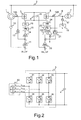
- Fig. 1 is a block diagram of a controller for a wound-rotor induction motor according to first embodiment of the present invention.
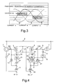
- Fig. 2 is a circuit block diagram for explaining an operation of the controller shown in Fig. 1.
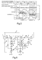
- Fig. 3 is a waveform diagram for explaining an operation of the circuit block diagram shown in Fig. 2.
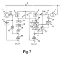
- Fig. 4 is a block diagram of a controller for a wound-rotor induction motor according to second embodiment of the present invention.
- Fig. 5 is a waveform diagram for explaining an operation of the controller shown in Fig. 4.
- Fig. 6 is a block diagram of a controller for a wound-rotor induction motor according to third embodiment of the present invention.
- Fig. 7 is a block diagram of a controller for a wound-rotor induction motor according to fourth embodiment of the present invention.
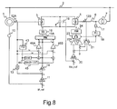
- Fig. 8 is a block diagram of a controller for a wound-rotor induction motor according to fifth embodiment of the present invention.
- Fig. 9 is a block diagram of a controller for a wound-rotor induction motor according to sixth embodiment of the present invention.
- Fig. 1 is a block diagram of the controller for a wound-rotor induction motor relating to first embodiment of the present invention.
- a wound-rotor induction motor 1 power is supplied from an AC power supply 2 to a primary winding, and secondary power induced in the secondary winding is supplied to a smoothing capacitor 4 via a voltage-type converter 3 composed of self extinguishing type switching elements.
- DC voltage applied to the smoothing capacitor 4 is converted to an AC voltage by a voltage-type converter 5.
- An output AC power from the voltage-type converter 5 is regenerated to the AC power supply 2 via a filter reactor 6 and a transformer 7.
- a speed detector 10 is attached to the wound-rotor induction motor 1.
- a speed feed-back signal detected by the speed detector10 and a referential speed signal SP_ref are compared and controlled by a speed controller 11.
- a secondary current from the wound-rotor induction motor 1 is detected by a current detector 12A and the signal is converted to a DC current by a diode rectifier circuit 13 and is compared and controlled with a referential current, which is an output of the speed controller 11, by a current controller 14.
- the gate of the self extinguishing type switching elements constituting the voltage-type converter 3 is PWM-controlled via a PWM circuit 15 and a selection switching circuit 16.
- the PWM control is a control by pulse width modulation and it indicates a method for changing the pulse width of the self extinguishing type switching elements constituting a converter to control an average output voltage of the converter.
- the constitution of the controller of the voltage-type converter 5 will be explained.
- the AC supply voltage of the transformer 7 on the secondary side is detected by a voltage detector 17 and an AC power phase ⁇ is obtained by a phase-locked loop (PLL) circuit 18.
- a DC voltage of the smoothing capacitor 4 is detected by a voltage detector 19, and the DC voltage and a referential voltage signal Vdc_ref are compared and controlled by a voltage controller 20, and a regenerative current referential signal is obtained.
- An AC output current of the voltage-type converter 5 is detected by a current detector 12B and the AC output current is decomposed into an active current of the DC amount and a reactive current thereof by a coordinate conversion circuit 21 for setting the AC power phase ⁇ aforementioned to a referential phase.
- the active current and a regenerative current referential signal are compared and controlled by a current controller 22A, and the reactive current and a zero current referential signal for controlling the reactive current to zero are compared and controlled by a current controller 22B.
- Two control outputs of the current controllers 22A and 22B are converted from two phases to three phases by a coordinate conversion circuit 23, and a 3-phase voltage referential signal is obtained, and gates of the self extinguishing type switching elements constituting the voltage-type converter 5 are controlled by pulse width modulation via a PWM circuit 24.
- the voltage-type converter 5 controls the DC voltage to a referential voltage Vdc_ref and controls the reactive current to zero, so that a power factor 1.0 of the voltage-type converter5 can be obtained.
- Fig. 2 is a circuit block diagram for explaining the operation of the voltage-type converter 3.
- the secondary winding of the wound-rotor induction motor 1 generates an AC voltage at a slip frequency with amplitude proportional to the slip frequency.
- the secondary winding has winding impedance, so that it may be expressed by an equivalent circuit 30.
- the voltage-type converter 3, as shown in Fig. 2 includes six self extinguishing type switching elements 31 to 36 in a bridge shape. Each of the self extinguishing type switching elements has a flywheel diode in anti-parallel connection.
- the self extinguishing type switching elements 31, 32, and 33 constitute a upper arm of the voltage-type converter 3, and the self extinguishing type switching elements 34, 35, and 36 constitute a lower arm thereof.
- the wound-rotor induction motor 1 to increase the secondary current of the wound-rotor induction motor 1, for example, turns on the self extinguishing type switching elements 31, 32, and 33 and turns off the self extinguishing type switching elements 34, 35, and 36.
- the three phases are short circuited and according to the current increase rate depending on the secondary winding voltage and the winding impedance, the current is increased.
- the self extinguishing type switching elements 31, 32, and 33 short-circuited are turned off. At this time, the flowing current passes the flywheel diode shown in Fig. 2, charges the smoothing capacitor 4, and stores the secondary power in the smoothing capacitor 4.
- the ON-OFF operation aforementioned is repeated, and the ratio of the ON period to make a short circuit is adjusted, thus the secondary current (secondary power) may be controlled.
- Fig. 3 shows an example of voltage wave form and current waveforms in the operation. This is an example that a modulation frequency of the PWM circuit 15 is higher than a slip frequency. The switching operation is performed in a state that ON period to make the short circuit of secondary winding and OFF period to open the circuit by PWM signal are almost same.
- the drawing shows that the current waveform in each phase is a sinusoidal wave shaped proportional to the secondary winding voltage.
- the elements to be turned on are the self extinguishing type switching elements 31, 32, and 33 of the upper arm.
- the self extinguishing type switching elements 34, 35, and 36 of the lower arm may be turned on.
- a switching loss of the self extinguishing type switching elements 31 to 36 may be averaged.
- the conversion efficiency in this embodiment will be considered. Under the aforementioned control, when the current path at the ON time is taken into account, the current flows through one self extinguishing type switching element and one diode. And, at the OFF time, the current flows through two diodes and charges the smoothing capacitor 4. On the other hand, in the secondary chopper system indicated in aforementioned Patent Publication, at the ON time, the current flows through one self extinguishing type switching element and two diodes. And, at the OFF time, the current flows through three diodes and charges the smoothing capacitor 4. Therefore, it is clear that the power supply loss is reduced and the conversion efficiency is improved by the present invention.
- the switching loss may be balanced and the capacity of the converter may be effectively used at its maximum.
- the same as the voltage-type converter 5 which is a converter on the power supply side may be used, thus an apparatus including shared and standardized spare parts may be used.
- the secondary current of the induction motor may be controlled to a sinusoidal wave shape, so that there is an excellent respect obtained that ripple torque of a frequency 6 times of the slip frequency generated by the 6-pulse diode converter of the conventional Scherbius apparatus is not generated in principle.
- the modulation system of the PWM circuit 15 may be controlled by either of the instantaneous current comparison system or the triangular wave comparison system.
- Fig. 4 is a block diagram of the controller for a wound-rotor induction motor relating to second embodiment of the present invention.
- the instantaneous value signal of the secondary current is inputted to the selection switching circuit 16A.
- the selection switching circuit 16A selects the mode of an upper arm of the first voltage type converter or a lower arm thereof to make a short circuit of the secondary winding of the wound-rotor induction motor, and select the mode so as not to switch a phase in which an absolute value of current is maximized among three phases currents detected by the secondary current detector12A.
- the operation waveform diagram shown in Fig. 5 shows the situation that either of the upper arm or the lower arm is selected. In a period of T1, phase W of positive current takes maximum absolute value, so that the selection switching circuit 16A selects the lower arm of the first voltage type converter.
- phase V of negative current takes maximum absolute value, so that the selection switching circuit 16A selects the upper arm of the first voltage type converter, and in a period of T3, phase U of positive current takes maximum absolute value, so that the selection switching circuit 16A selects the lower arm of the first voltage type converter, and so on.
- a current always averaged may be turned on or off.
- the switching loss of the self extinguishing type switching elements if the current to be turned on or off increases, increases in proportion to a value between an amount of the current and the square of the amount of the current, so that according to second embodiment, it is possible to more reduce the switching loss and more improve the conversion efficiency.
- Fig. 6 is a block diagram of the controller for a wound-rotor induction motor relating to third embodiment of the present invention.
- third embodiment uses so called feed-forward control.
- Fig. 7 is a block diagram of the controller for a wound-rotor induction motor relating to fourth embodiment of the present invention.
- a PLL conversion circuit 42 for inputting an instantaneous value signal of the secondary current is installed in place of the speed detector 10, and the output thereof is used as a speed feed-back signal as shown in Fig. 7 .
- a secondary AC current signal detected by the current detector12A is inputted to the PLL conversion circuit 42.
- the PLL conversion circuit 42 removes a noise signal and detects a fundamental wave, so that it converts it to a frequency of the secondary current by a simple conversion operation.
- the secondary current flows in proportion to the secondary winding voltage, so that the frequency detected from the secondary current is a slip frequency.
- the slip frequency detected is subtracted from the frequency of the power supply in the PLL conversion circuit 42, thus the rotating frequency of the motor is detected.
- Fig. 8 is a block diagram of the controller for a wound-rotor induction motor relating to fifth embodiment of the present invention.
- a PLL circuit 43, sinusoidal wave function circuits 44 and 45, and controllers 46A and 46B are used in fifth embodiment as shown in Fig. 8.
- the PLL circuit 43 detects a phase ⁇ of the secondary current, and sinusoidal wave function circuits 44 and 45 generate sinusoidal wave signals Sin ⁇ and Sin ( ⁇ +120°) according to the phase ⁇ respectively.
- Sinusoidal wave signals Sin ⁇ and Sin( ⁇ +120°) are multiplied by the secondary referential current, referential signals of a phase-U sinusoidal wave current and a phase-W sinusoidal wave current based on an AC instantaneous value are obtained respectively.
- the referential signal of a phase-U sinusoidal wave current is compared with a secondary current detection signal iu and controlled by a controller 46A.
- the referential signal of a phase-w sinusoidal wave current is compared with a secondary current detection signal iw and controlled by a controller 46B.
- Output obtained by controllers 46A and 46B is inputted to a PWM circuit 15A.
- each phase of the voltage-type converter 3 can be controlled individually, so that in the three phases, the instantaneous value waveforms may be controlled to a sinusoidal wave.
- the reason that the phase V is omitted here is that the total of instantaneous values of the three-phase current is zero, so that operations can be performed.
- the current waveform in each phase is controlled to an ideal sinusoidal wave, and the harmonic component of the secondary current is substantially reduced to zero, and no ripple torque is generated.
- Fig. 9 is a block diagram of the controller for a wound-rotor induction motor relating to sixth embodiment of the present invention.
- the referential reactive current is set to Q_ref for canceling a lagging current generated by the wound-rotor induction motor 1 instead of zero as shown in Fig 9.
- the reactive current for canceling the lagging current generated by the wound-rotor induction motor 1 flows through the primary side of the transformer 7 in this way, thus the power factor of the whole system can be controlled to 1.0.
Landscapes
- Engineering & Computer Science (AREA)
- Power Engineering (AREA)
- Control Of Ac Motors In General (AREA)
Applications Claiming Priority (1)
| Application Number | Priority Date | Filing Date | Title |
|---|---|---|---|
| JP2004322001A JP4549159B2 (ja) | 2004-11-05 | 2004-11-05 | 巻線型誘導電動機の制御装置 |
Publications (2)
| Publication Number | Publication Date |
|---|---|
| EP1655828A1 true EP1655828A1 (de) | 2006-05-10 |
| EP1655828B1 EP1655828B1 (de) | 2010-06-09 |
Family
ID=35874576
Family Applications (1)
| Application Number | Title | Priority Date | Filing Date |
|---|---|---|---|
| EP05024136A Expired - Lifetime EP1655828B1 (de) | 2004-11-05 | 2005-11-04 | Steuerung für eine doppelt-gespeiste Asynchronmaschine |
Country Status (5)
| Country | Link |
|---|---|
| US (1) | US7042194B1 (de) |
| EP (1) | EP1655828B1 (de) |
| JP (1) | JP4549159B2 (de) |
| CN (1) | CN100399697C (de) |
| DE (1) | DE602005021736D1 (de) |
Cited By (2)
| Publication number | Priority date | Publication date | Assignee | Title |
|---|---|---|---|---|
| RU2399149C1 (ru) * | 2008-12-31 | 2010-09-10 | Государственное образовательное учреждение высшего профессионального образования "Казанский государственный энергетический университет" (КГЭУ) | Электропривод |
| DE102023119025A1 (de) * | 2023-07-19 | 2025-01-23 | Schaeffler Technologies AG & Co. KG | Steuereinheit und Verfahren zum Steuern eines Betriebs einer Drehstrom-Maschine, Computerprogrammprodukt und Antriebsstrang |
Families Citing this family (10)
| Publication number | Priority date | Publication date | Assignee | Title |
|---|---|---|---|---|
| US7834577B2 (en) * | 2005-05-13 | 2010-11-16 | Tm Ge Automation Systems Llc | System and method for starting a wound rotor motor |
| US8704482B2 (en) | 2009-04-23 | 2014-04-22 | Mitsubishi Electric Corporation | Power conversion device |
| JP5026553B2 (ja) * | 2010-04-22 | 2012-09-12 | ファナック株式会社 | Ac/dcコンバータの変換動作モードを動的に切替える機能を有するモータ駆動装置 |
| JP4955806B2 (ja) * | 2010-09-03 | 2012-06-20 | ファナック株式会社 | Dcリンク電圧の安定化機能を有するモータ駆動装置 |
| KR101422905B1 (ko) * | 2012-01-30 | 2014-07-23 | 엘에스산전 주식회사 | 고압인버터 제어장치 및 고압인버터 시스템 |
| DE102014222338A1 (de) * | 2014-10-31 | 2016-06-09 | Continental Automotive Gmbh | Vorrichtung und Verfahren zum Steuern einer Fluidpumpe für ein Kraftfahrzeug |
| JP6711255B2 (ja) * | 2016-12-08 | 2020-06-17 | 株式会社デンソー | モータ制御装置、および、これを用いた電動パワーステアリング装置 |
| RU2661343C1 (ru) * | 2017-01-30 | 2018-07-16 | Федеральное государственное бюджетное образовательное учреждение высшего образования "Липецкий государственный технический университет" (ЛГТУ) | Способ управления асинхронным двигателем с фазным ротором |
| US10381968B2 (en) * | 2017-12-05 | 2019-08-13 | Otis Elevator Company | Converter pulse width modulation strategies for three phase regenerative drives |
| JP7096792B2 (ja) * | 2019-07-19 | 2022-07-06 | 株式会社日立製作所 | 電流計測器および電力変換装置 |
Citations (5)
| Publication number | Priority date | Publication date | Assignee | Title |
|---|---|---|---|---|
| JPS60249893A (ja) * | 1984-05-24 | 1985-12-10 | Toshiba Corp | 巻線形誘導電動機の二次チヨツパ−制御装置 |
| JPS63202290A (ja) * | 1987-02-14 | 1988-08-22 | Hitachi Ltd | 誘導機の速度制御方法 |
| JPH0487592A (ja) * | 1990-07-25 | 1992-03-19 | Toshiba Corp | 巻線形誘導電動機の速度制御装置 |
| JP2001025291A (ja) * | 1999-07-06 | 2001-01-26 | Fuji Electric Co Ltd | 巻線形誘導電動機の制御装置 |
| JP2003134871A (ja) | 2001-10-19 | 2003-05-09 | Hitachi Ltd | 誘導機の速度制御装置 |
Family Cites Families (13)
| Publication number | Priority date | Publication date | Assignee | Title |
|---|---|---|---|---|
| US3699416A (en) * | 1971-07-02 | 1972-10-17 | Sevcon Eng Ltd | Dynamic braking of wound motor polyphase induction motors |
| JPS60255090A (ja) * | 1984-05-26 | 1985-12-16 | Toshiba Corp | セルビウスシステム |
| GB2167251B (en) * | 1984-11-21 | 1988-10-05 | Barry Wayne Williams | Induction motor drive circuits |
| JP2569016B2 (ja) | 1986-09-01 | 1997-01-08 | 株式会社日立製作所 | 誘導機の制御装置 |
| JPS63287397A (ja) * | 1987-05-20 | 1988-11-24 | Mitsubishi Electric Corp | 誘導電動機の制御装置 |
| JPH03128691A (ja) * | 1989-07-27 | 1991-05-31 | Seiko Epson Corp | 電圧形pwmコンバータ・インバータシステムとその制御方式 |
| DE4241152A1 (de) * | 1992-12-07 | 1994-06-09 | Patent Treuhand Ges Fuer Elektrische Gluehlampen Mbh | Dotiertes Quarzglas und daraus hergestellte Gegenstände |
| JP3395427B2 (ja) * | 1995-02-16 | 2003-04-14 | 株式会社日立製作所 | セルビウス制御装置 |
| US6075717A (en) * | 1996-05-01 | 2000-06-13 | General Electric Company | PWM rectifier control with switching losses equally distributed among multiple switching devices |
| US6269010B1 (en) * | 2000-02-29 | 2001-07-31 | Rockwell Technologies, Llc | CSI based drive having feedforward control of inverter input voltage |
| JP3772649B2 (ja) * | 2000-06-30 | 2006-05-10 | 株式会社日立製作所 | 誘導機の速度制御装置 |
| US6448735B1 (en) * | 2001-04-26 | 2002-09-10 | Abb Automation Inc. | Controller for a wound rotor slip ring induction machine |
| CN2612151Y (zh) * | 2003-04-04 | 2004-04-14 | 天津电气传动设计研究所 | 利用低压变频技术实现中压电机变频调速的变频器 |
-
2004
- 2004-11-05 JP JP2004322001A patent/JP4549159B2/ja not_active Expired - Lifetime
-
2005
- 2005-09-28 US US11/236,577 patent/US7042194B1/en not_active Expired - Lifetime
- 2005-11-04 DE DE602005021736T patent/DE602005021736D1/de not_active Expired - Lifetime
- 2005-11-04 CN CNB2005101186850A patent/CN100399697C/zh not_active Expired - Lifetime
- 2005-11-04 EP EP05024136A patent/EP1655828B1/de not_active Expired - Lifetime
Patent Citations (5)
| Publication number | Priority date | Publication date | Assignee | Title |
|---|---|---|---|---|
| JPS60249893A (ja) * | 1984-05-24 | 1985-12-10 | Toshiba Corp | 巻線形誘導電動機の二次チヨツパ−制御装置 |
| JPS63202290A (ja) * | 1987-02-14 | 1988-08-22 | Hitachi Ltd | 誘導機の速度制御方法 |
| JPH0487592A (ja) * | 1990-07-25 | 1992-03-19 | Toshiba Corp | 巻線形誘導電動機の速度制御装置 |
| JP2001025291A (ja) * | 1999-07-06 | 2001-01-26 | Fuji Electric Co Ltd | 巻線形誘導電動機の制御装置 |
| JP2003134871A (ja) | 2001-10-19 | 2003-05-09 | Hitachi Ltd | 誘導機の速度制御装置 |
Non-Patent Citations (4)
| Title |
|---|
| PATENT ABSTRACTS OF JAPAN vol. 010, no. 117 (E - 400) 2 May 1986 (1986-05-02) * |
| PATENT ABSTRACTS OF JAPAN vol. 012, no. 486 (E - 695) 19 December 1988 (1988-12-19) * |
| PATENT ABSTRACTS OF JAPAN vol. 016, no. 316 (E - 1231) 10 July 1992 (1992-07-10) * |
| PATENT ABSTRACTS OF JAPAN vol. 2000, no. 16 8 May 2001 (2001-05-08) * |
Cited By (3)
| Publication number | Priority date | Publication date | Assignee | Title |
|---|---|---|---|---|
| RU2399149C1 (ru) * | 2008-12-31 | 2010-09-10 | Государственное образовательное учреждение высшего профессионального образования "Казанский государственный энергетический университет" (КГЭУ) | Электропривод |
| DE102023119025A1 (de) * | 2023-07-19 | 2025-01-23 | Schaeffler Technologies AG & Co. KG | Steuereinheit und Verfahren zum Steuern eines Betriebs einer Drehstrom-Maschine, Computerprogrammprodukt und Antriebsstrang |
| DE102023119025B4 (de) * | 2023-07-19 | 2025-05-08 | Schaeffler Technologies AG & Co. KG | Steuereinheit und Verfahren zum Steuern eines Betriebs einer Drehstrom-Maschine, Computerprogrammprodukt und Antriebsstrang |
Also Published As
| Publication number | Publication date |
|---|---|
| JP2006136121A (ja) | 2006-05-25 |
| DE602005021736D1 (de) | 2010-07-22 |
| CN1770619A (zh) | 2006-05-10 |
| US20060097689A1 (en) | 2006-05-11 |
| EP1655828B1 (de) | 2010-06-09 |
| JP4549159B2 (ja) | 2010-09-22 |
| CN100399697C (zh) | 2008-07-02 |
| US7042194B1 (en) | 2006-05-09 |
Similar Documents
| Publication | Publication Date | Title |
|---|---|---|
| US8570775B2 (en) | CMV reduction under bus transient condition | |
| US7170767B2 (en) | System and method for regenerative PWM AC power conversion | |
| US5621628A (en) | Power converter | |
| US11211879B2 (en) | Capacitor size reduction and lifetime extension for cascaded H-bridge drives | |
| JP4445470B2 (ja) | 電源装置 | |
| US6542390B2 (en) | System and method for regenerative PWM AC power conversion | |
| US9735666B2 (en) | Power conversion device | |
| WO2020115800A1 (ja) | 電力変換装置 | |
| JPH04197097A (ja) | 交流電動機可変速システム | |
| US7042194B1 (en) | Controller for a wound-rotor induction motor | |
| JP4340843B2 (ja) | 交流直流複合電源装置 | |
| JP3758059B2 (ja) | 同期電動機の駆動制御装置 | |
| Bode et al. | A novel hysteresis current controller for multilevel single phase voltage source inverters | |
| JPH08251947A (ja) | 電力変換装置の回生制御装置 | |
| JP4755504B2 (ja) | 電力変換装置 | |
| JP2000139085A (ja) | 電力変換装置 | |
| JP2014023310A (ja) | コンバータシステムの制御方法および制御装置 | |
| JPH09149647A (ja) | コンバータの制御装置 | |
| JPH09163751A (ja) | Pwm制御自励式整流装置 | |
| JPS5961475A (ja) | 電力変換装置 | |
| JPH11215849A (ja) | パルス幅変調電力変換装置 | |
| JP3381590B2 (ja) | サイリスタ変換装置 | |
| JPH06169501A (ja) | 電気車の電力変換装置 | |
| JP2025121657A (ja) | コンバータ制御装置 | |
| JP2004104933A (ja) | Pwmインバータの制御方法 |
Legal Events
| Date | Code | Title | Description |
|---|---|---|---|
| PUAI | Public reference made under article 153(3) epc to a published international application that has entered the european phase |
Free format text: ORIGINAL CODE: 0009012 |
|
| 17P | Request for examination filed |
Effective date: 20051104 |
|
| AK | Designated contracting states |
Kind code of ref document: A1 Designated state(s): AT BE BG CH CY CZ DE DK EE ES FI FR GB GR HU IE IS IT LI LT LU LV MC NL PL PT RO SE SI SK TR |
|
| AX | Request for extension of the european patent |
Extension state: AL BA HR MK YU |
|
| 17Q | First examination report despatched |
Effective date: 20061018 |
|
| AKX | Designation fees paid |
Designated state(s): CH DE LI |
|
| GRAP | Despatch of communication of intention to grant a patent |
Free format text: ORIGINAL CODE: EPIDOSNIGR1 |
|
| GRAS | Grant fee paid |
Free format text: ORIGINAL CODE: EPIDOSNIGR3 |
|
| GRAA | (expected) grant |
Free format text: ORIGINAL CODE: 0009210 |
|
| AK | Designated contracting states |
Kind code of ref document: B1 Designated state(s): CH DE LI |
|
| REG | Reference to a national code |
Ref country code: CH Ref legal event code: EP |
|
| REG | Reference to a national code |
Ref country code: CH Ref legal event code: NV Representative=s name: E. BLUM & CO. AG PATENT- UND MARKENANWAELTE VSP |
|
| REF | Corresponds to: |
Ref document number: 602005021736 Country of ref document: DE Date of ref document: 20100722 Kind code of ref document: P |
|
| PLBE | No opposition filed within time limit |
Free format text: ORIGINAL CODE: 0009261 |
|
| STAA | Information on the status of an ep patent application or granted ep patent |
Free format text: STATUS: NO OPPOSITION FILED WITHIN TIME LIMIT |
|
| 26N | No opposition filed |
Effective date: 20110310 |
|
| REG | Reference to a national code |
Ref country code: DE Ref legal event code: R097 Ref document number: 602005021736 Country of ref document: DE Effective date: 20110309 |
|
| PGFP | Annual fee paid to national office [announced via postgrant information from national office to epo] |
Ref country code: DE Payment date: 20241001 Year of fee payment: 20 |
|
| PGFP | Annual fee paid to national office [announced via postgrant information from national office to epo] |
Ref country code: CH Payment date: 20241201 Year of fee payment: 20 |
|
| REG | Reference to a national code |
Ref country code: CH Ref legal event code: H14 Free format text: ST27 STATUS EVENT CODE: U-0-0-H10-H14 (AS PROVIDED BY THE NATIONAL OFFICE) Effective date: 20251104 Ref country code: DE Ref legal event code: R071 Ref document number: 602005021736 Country of ref document: DE |