EP1656874A2 - Aspirateur avec sécurité thermique du moteur - Google Patents
Aspirateur avec sécurité thermique du moteur Download PDFInfo
- Publication number
- EP1656874A2 EP1656874A2 EP05024573A EP05024573A EP1656874A2 EP 1656874 A2 EP1656874 A2 EP 1656874A2 EP 05024573 A EP05024573 A EP 05024573A EP 05024573 A EP05024573 A EP 05024573A EP 1656874 A2 EP1656874 A2 EP 1656874A2
- Authority
- EP
- European Patent Office
- Prior art keywords
- electric motor
- temperature
- motor
- detector
- vacuum cleaner
- Prior art date
- Legal status (The legal status is an assumption and is not a legal conclusion. Google has not performed a legal analysis and makes no representation as to the accuracy of the status listed.)
- Granted
Links
Images



Classifications
-
- A—HUMAN NECESSITIES
- A47—FURNITURE; DOMESTIC ARTICLES OR APPLIANCES; COFFEE MILLS; SPICE MILLS; SUCTION CLEANERS IN GENERAL
- A47L—DOMESTIC WASHING OR CLEANING; SUCTION CLEANERS IN GENERAL
- A47L9/00—Details or accessories of suction cleaners, e.g. mechanical means for controlling the suction or for effecting pulsating action; Storing devices specially adapted to suction cleaners or parts thereof; Carrying-vehicles specially adapted for suction cleaners
- A47L9/28—Installation of the electric equipment, e.g. adaptation or attachment to the suction cleaner; Controlling suction cleaners by electric means
- A47L9/2889—Safety or protection devices or systems, e.g. for prevention of motor over-heating or for protection of the user
-
- A—HUMAN NECESSITIES
- A47—FURNITURE; DOMESTIC ARTICLES OR APPLIANCES; COFFEE MILLS; SPICE MILLS; SUCTION CLEANERS IN GENERAL
- A47L—DOMESTIC WASHING OR CLEANING; SUCTION CLEANERS IN GENERAL
- A47L9/00—Details or accessories of suction cleaners, e.g. mechanical means for controlling the suction or for effecting pulsating action; Storing devices specially adapted to suction cleaners or parts thereof; Carrying-vehicles specially adapted for suction cleaners
- A47L9/02—Nozzles
- A47L9/04—Nozzles with driven brushes or agitators
- A47L9/0405—Driving means for the brushes or agitators
- A47L9/0411—Driving means for the brushes or agitators driven by electric motor
-
- A—HUMAN NECESSITIES
- A47—FURNITURE; DOMESTIC ARTICLES OR APPLIANCES; COFFEE MILLS; SPICE MILLS; SUCTION CLEANERS IN GENERAL
- A47L—DOMESTIC WASHING OR CLEANING; SUCTION CLEANERS IN GENERAL
- A47L9/00—Details or accessories of suction cleaners, e.g. mechanical means for controlling the suction or for effecting pulsating action; Storing devices specially adapted to suction cleaners or parts thereof; Carrying-vehicles specially adapted for suction cleaners
- A47L9/28—Installation of the electric equipment, e.g. adaptation or attachment to the suction cleaner; Controlling suction cleaners by electric means
- A47L9/2805—Parameters or conditions being sensed
-
- A—HUMAN NECESSITIES
- A47—FURNITURE; DOMESTIC ARTICLES OR APPLIANCES; COFFEE MILLS; SPICE MILLS; SUCTION CLEANERS IN GENERAL
- A47L—DOMESTIC WASHING OR CLEANING; SUCTION CLEANERS IN GENERAL
- A47L9/00—Details or accessories of suction cleaners, e.g. mechanical means for controlling the suction or for effecting pulsating action; Storing devices specially adapted to suction cleaners or parts thereof; Carrying-vehicles specially adapted for suction cleaners
- A47L9/28—Installation of the electric equipment, e.g. adaptation or attachment to the suction cleaner; Controlling suction cleaners by electric means
- A47L9/2805—Parameters or conditions being sensed
- A47L9/2831—Motor parameters, e.g. motor load or speed
-
- A—HUMAN NECESSITIES
- A47—FURNITURE; DOMESTIC ARTICLES OR APPLIANCES; COFFEE MILLS; SPICE MILLS; SUCTION CLEANERS IN GENERAL
- A47L—DOMESTIC WASHING OR CLEANING; SUCTION CLEANERS IN GENERAL
- A47L9/00—Details or accessories of suction cleaners, e.g. mechanical means for controlling the suction or for effecting pulsating action; Storing devices specially adapted to suction cleaners or parts thereof; Carrying-vehicles specially adapted for suction cleaners
- A47L9/28—Installation of the electric equipment, e.g. adaptation or attachment to the suction cleaner; Controlling suction cleaners by electric means
- A47L9/2836—Installation of the electric equipment, e.g. adaptation or attachment to the suction cleaner; Controlling suction cleaners by electric means characterised by the parts which are controlled
- A47L9/2842—Suction motors or blowers
-
- A—HUMAN NECESSITIES
- A47—FURNITURE; DOMESTIC ARTICLES OR APPLIANCES; COFFEE MILLS; SPICE MILLS; SUCTION CLEANERS IN GENERAL
- A47L—DOMESTIC WASHING OR CLEANING; SUCTION CLEANERS IN GENERAL
- A47L9/00—Details or accessories of suction cleaners, e.g. mechanical means for controlling the suction or for effecting pulsating action; Storing devices specially adapted to suction cleaners or parts thereof; Carrying-vehicles specially adapted for suction cleaners
- A47L9/28—Installation of the electric equipment, e.g. adaptation or attachment to the suction cleaner; Controlling suction cleaners by electric means
- A47L9/2857—User input or output elements for control, e.g. buttons, switches or displays
-
- A—HUMAN NECESSITIES
- A47—FURNITURE; DOMESTIC ARTICLES OR APPLIANCES; COFFEE MILLS; SPICE MILLS; SUCTION CLEANERS IN GENERAL
- A47L—DOMESTIC WASHING OR CLEANING; SUCTION CLEANERS IN GENERAL
- A47L9/00—Details or accessories of suction cleaners, e.g. mechanical means for controlling the suction or for effecting pulsating action; Storing devices specially adapted to suction cleaners or parts thereof; Carrying-vehicles specially adapted for suction cleaners
- A47L9/28—Installation of the electric equipment, e.g. adaptation or attachment to the suction cleaner; Controlling suction cleaners by electric means
- A47L9/2857—User input or output elements for control, e.g. buttons, switches or displays
- A47L9/2863—Control elements activated by pivoting movement of the upright vacuum cleaner handle
Definitions
- the present invention relates to a vacuum cleaner; and, more particularly, to a control mechanism for an electric motor for driving a rotational brush which brushes dust particles.
- vacuum cleaner main body 50 includes electric blower 51 for generating a suction air stream for sucking in dust particles and dust chamber 52 for collecting dust particles therein, wherein dust chamber 52 is provided at a suction side of electric blower 51, i.e., above electric blower 51.
- Hose 60 communicated at one end thereof with dust chamber 52 is installed at a frontal portion of vacuum cleaner main body 50, and the other end of hose 60 is connected to suction head 80 including rotational brush 53, electric motor 81 for driving the rotational brush 53, and so forth.
- Suction head 80, hose 60 and dust chamber 52 form an air suction passage.
- a user controls operations of electric blower 51 and electric motor 81 for rotating rotational brush 53 depending on the state of a floor to be cleaned by manipulating switch 82 installed on handle 54.
- electric motor 81 is cooled down by the air stream that is made to flow in the air suction passage by the operation of electric blower 51 (see, for example, specification of US Patent No. 6533611).
- a temperature sensor in general especially the one with the self-hold function is of a high price.
- an object of the present invention to provide a low-cost vacuum cleaner having a high safety and an increased user convenience.
- a vacuum cleaner including: an electric motor for driving a rotational brush for brushing dust particles from a surface to be cleaned; an electric blower for generating a suction air stream for sucking in the dust particles; a dust chamber for collecting the dust particles therein; a motor controller for controlling the electric motor; an input controller for controlling the electric blower; a current detector for detecting a current flowing through the motor controller; and a temperature detector for detecting a temperature of the electric motor, wherein if the temperature of the electric motor increases over a predetermined temperature value, the electric motor is stopped and the stoppage of the electric motor is detected by the current detector.
- a vacuum cleaner including: an electric motor for driving a rotational brush for brushing dust particles from a surface to be cleaned; an electric blower for generating a suction air stream for sucking in the dust particles; a dust chamber for storing the dust particles therein; a motor controller for controlling the electric motor; an input controller for controlling the electric blower; a motor detector for detecting whether the electric motor is being driven or not; and a temperature detector for detecting a temperature of the electric motor, wherein the electric motor is stopped unless outputs from the motor detector and the temperature detector are in.
- Fig. 1 is a side view of a vacuum cleaner in accordance with a first preferred embodiment of the present invention and Fig. 2 sets forth a circuit block diagram thereof.
- the vacuum cleaner includes electric motor 1 for driving rotational brush 2 for brushing dust particles on a floor to be cleaned; electric blower 3 for generating suction air stream for sucking in dust particles; dust chamber 4 for collecting dust particles therein; motor controller 5 for controlling the rotational speed of electric motor 1; input control unit 6 for controlling electric blower 3; and current detector 7 for detecting an electric current flowing through motor controller 5.
- temperature detector 8 detects the temperature of electric motor 1.
- temperature detector 8 includes cheap thermostat 9 (of a self-reset type) and is connected to electric motor 1 in series. As for thermostat 9, if the temperature of electric motor 1 increases up to a first predetermined value (e.g., 120 °C), a closed contact point of thermostat 9 is opened, whereas the opened contact point is closed again if electric motor 1 is cooled down such that its temperature decreases to a second predetermined value (e.g., 70 °C). Further, switch 10 installed on a handle of the vacuum cleaner is used for a user to turn on or off the operation of the vacuum cleaner.
- a first predetermined value e.g. 120 °C
- rotational brush 2 is operated at a low rotational speed for a long period of time or if rotational brush 2 is locked due to a heavy load of the surface to be cleaned, such as a thick, heavy carpet or electric motor 1 itself is locked, the temperature of electric motor 1 increases. In this case, if the temperature of electric motor 1 is detected to reach the first predetermined temperature value by temperature detector 8, the contact point of thermostat 9 of temperature detector 8 is opened, and at the same time current detector 7 will detect there is no current flowing through motor controller 5.
- motor controller 5 controls to have switch 10 to be turned off or outputs a stop signal of electric motor 1 continuously until switch 10 is turned off or power supply is cut off. For example, if it is determined that electric motor 1 is stopped, the power is not supplied to electric motor 1 until switch 10 is turned off or power supply is cut off.
- switch 10 which is a power switch for starting or cutting off a power supply
- switch 10 is exemplified as an "off" switch for use in stopping the load on electric motor 1 or electric blower 3 in the above-described first preferred embodiment
- a signal switch (not shown) instead of the power switch to generate an "off" signal.
- the load can be stopped. That is, the "off" switch can be implemented by an element other than the power switch.
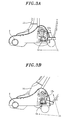
- Figs. 3A and 3B present partial cross sectional views of major components of a vacuum cleaner in accordance with a second preferred embodiment of the present invention.
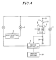
- Fig. 4 is a circuit block diagram thereof.
- parts identical to those described in the first preferred embodiment will be assigned same reference numerals, and description thereof will be omitted.
- electric motor detector 11 detects whether electric motor 1 is being driven or not.
- micro switch 12 for distinguishing a state where rotational brush 2 is not driven, i.e., a main body standing state (as shown in Fig. 3A) in which main body 15 stands upright from a state where main body 15 is inclined to drive rotational brush 2, i.e., a cleaning state (as shown in Fig. 3B).
- Reference numeral 12a is a lever of micro switch 12.
- lever 12a of micro switch 12 When main body 15 is in the standing state, lever 12a of micro switch 12 is opened, as illustrated in Fig. 3A, so that a contact point of micro switch 12 is also in an open state.
- lever 12a of micro switch 12 is closed, as shown in Fig. 3B.
- temperature detector 8 includes thermostat 9 and first fixed resistor 13 (e.g., 1 k ⁇ ) connected to thermostat 9 in parallel. Also, electric motor detector 11 is connected to temperature detector 8 in series, which is also connected to second fixed resistor 14 (which is set to have a value of 1 k ⁇ identical to that of first fixed resistor 13) in series. In this configuration, a voltage divided by first and second resistor 13 and 14 can be inputted to motor controller 5.
- first fixed resistor 13 e.g., 1 k ⁇
- electric motor detector 11 is connected to temperature detector 8 in series, which is also connected to second fixed resistor 14 (which is set to have a value of 1 k ⁇ identical to that of first fixed resistor 13) in series.
- second fixed resistor 14 which is set to have a value of 1 k ⁇ identical to that of first fixed resistor 13
- detection of a current state of the vacuum cleaner and control operation are performed as follows based on an input voltage to motor controller 5. If an input of 0.0V is detected, main body 15 is determined to be in the standing state, so that electric motor 1 is stopped; if an input of 2.5V is detected, main body 15 is determined to be in the cleaning state, but since the temperature of electric motor 1 is high, electric motor 1 is maintained stopped; and if an input of 5.0V is detected, main body 15 is determined to be in the cleaning state and the temperature of electric motor 1 is low, so that electric motor 1 is operated.
- a stop signal indicating the stoppage of electric motor 1 is continuously outputted until an "off-operation" is inputted by switch 10 or power supply is cut off.
- the temperature of electric motor 1 is reduced to, e.g., the second predetermined value, electric motor 1 is maintained stopped without being driven to rotate unprepared.
- thermostat 9 and first fixed resistor 13 connected thereto in parallel are used as temperature detector 8
- a thermistor or the like is employed as temperature detector 8
- installation of the fixed resistor becomes unnecessary and it is still possible to perform a delicate control of the temperature of electric motor 1 (for example, with regard to a determination value for use in stopping a driving signal of electric motor 1 when the temperature of electric motor 1 increases and a determination value for allowing an output of the driving signal of electric motor 1 when the temperature of electric motor 1 decreases, the two values can be changed properly.
- driving switch 20 for use in resuming the driving operation of electric motor 1 manually is provided as shown in Fig. 4. If the temperature of electric motor 1 is reduced down to or below the second predetermined temperature value after electric motor 1 is stopped because its temperature increases up to or over the first predetermined value, it is possible to resume an output of a driving signal of electric motor 1 from motor controller 5 by manipulating driving switch 20. Thus, by using driving switch 20, unprepared rotation of electric motor 1 can be prevented when the temperature of electric motor 1 is reduced, and, also, a normal cleaning operation can be resumed by operating driving switch 20 at a point in time when the temperature of electric motor 1 falls below the second predetermined temperature value.
- the vacuum cleaner in accordance with the present invention has merits in that it can be fabricated at a low cost and there is little limit in the number of wirings therein. Furthermore, it can detect the stoppage of the electric motor accurately, thus providing improved safety and user convenience. Therefore, the present invention has advantages when it is applied to various vacuum cleaners or dust collectors for use in household and commercial environments.
- the rotational state of the electric motor can be detected at a low cost to secure a high level of safety readiness and it is possible to securely control the rotation of the electric motor when, e.g., the electric motor is abnormally overheated or the vacuum cleaner is not in a cleaning state. Moreover, it is possible to properly setting the stop temperature and the drive temperature of the electric motor to prevent the electric motor from being overloaded.
Landscapes
- Engineering & Computer Science (AREA)
- Mechanical Engineering (AREA)
- Electric Vacuum Cleaner (AREA)
- Nozzles For Electric Vacuum Cleaners (AREA)
- Means For Warming Up And Starting Carburetors (AREA)
- Control Of Electric Motors In General (AREA)
Applications Claiming Priority (1)
| Application Number | Priority Date | Filing Date | Title |
|---|---|---|---|
| JP2004328752A JP2006136512A (ja) | 2004-11-12 | 2004-11-12 | 電気掃除機 |
Publications (3)
| Publication Number | Publication Date |
|---|---|
| EP1656874A2 true EP1656874A2 (fr) | 2006-05-17 |
| EP1656874A3 EP1656874A3 (fr) | 2007-04-18 |
| EP1656874B1 EP1656874B1 (fr) | 2009-04-01 |
Family
ID=35717663
Family Applications (1)
| Application Number | Title | Priority Date | Filing Date |
|---|---|---|---|
| EP05024573A Expired - Lifetime EP1656874B1 (fr) | 2004-11-12 | 2005-11-10 | Aspirateur avec sécurité thermique du moteur |
Country Status (7)
| Country | Link |
|---|---|
| US (1) | US20060101605A1 (fr) |
| EP (1) | EP1656874B1 (fr) |
| JP (1) | JP2006136512A (fr) |
| CN (1) | CN100344254C (fr) |
| AT (1) | ATE427064T1 (fr) |
| DE (1) | DE602005013628D1 (fr) |
| ES (1) | ES2321731T3 (fr) |
Cited By (6)
| Publication number | Priority date | Publication date | Assignee | Title |
|---|---|---|---|---|
| WO2014177171A1 (fr) * | 2013-04-29 | 2014-11-06 | Aktiebolaget Electrolux | Buse destinée à un aspirateur et aspirateur |
| EP3241476A1 (fr) * | 2016-05-03 | 2017-11-08 | Koninklijke Philips N.V. | Aspirateur |
| CN109106287A (zh) * | 2018-09-17 | 2019-01-01 | 珠海格力电器股份有限公司 | 吸尘设备及其控制装置及方法 |
| EP2062517B1 (fr) * | 2006-09-11 | 2019-12-11 | Panasonic Corporation | Appareil de nettoyage électrique |
| WO2020163336A1 (fr) * | 2019-02-06 | 2020-08-13 | Techtronic Cordless Gp | Système de nettoyage comprenant un système pour empêcher le moteur de surchauffer et un procédé associé |
| EP4252606A1 (fr) * | 2022-03-30 | 2023-10-04 | Miele & Cie. KG | Aspirateur, de préférence aspirateur à main |
Families Citing this family (8)
| Publication number | Priority date | Publication date | Assignee | Title |
|---|---|---|---|---|
| US7321213B2 (en) * | 2005-07-20 | 2008-01-22 | Asmo Co., Ltd. | Motor controller |
| JP4818847B2 (ja) * | 2005-11-07 | 2011-11-16 | アスモ株式会社 | モータ制御装置 |
| JP5677064B2 (ja) * | 2010-12-10 | 2015-02-25 | 株式会社東芝 | 電気掃除機 |
| WO2018099543A1 (fr) * | 2016-11-30 | 2018-06-07 | Alfred Kärcher Gmbh & Co. Kg | Brosse de balayage |
| CN109276184B (zh) * | 2017-07-21 | 2022-03-29 | 添可电器有限公司 | 手持式吸尘器及其控制方法 |
| JP7123690B2 (ja) * | 2018-08-08 | 2022-08-23 | 東芝ライフスタイル株式会社 | 電気掃除機 |
| US11672390B2 (en) | 2019-11-13 | 2023-06-13 | Emerson Electric Co. | Vacuum cleaner motor assemblies and methods of operating same |
| CA3233854A1 (fr) | 2021-04-23 | 2022-10-27 | Fariha AHMED | Appareil de nettoyage a la vapeur |
Citations (1)
| Publication number | Priority date | Publication date | Assignee | Title |
|---|---|---|---|---|
| US6351872B1 (en) | 1999-07-16 | 2002-03-05 | Matsushita Electric Corporation Of America | Agitator motor projection system for vacuum cleaner |
Family Cites Families (11)
| Publication number | Priority date | Publication date | Assignee | Title |
|---|---|---|---|---|
| US2323554A (en) * | 1941-04-19 | 1943-07-06 | Richard D Mason | Vacuum cleaning apparatus |
| US5530987A (en) * | 1992-07-24 | 1996-07-02 | The Babcock & Wilcox Company | Condensate drain controller |
| US6085382A (en) * | 1997-01-10 | 2000-07-11 | White Consolidated Industries, Inc. | Air filtrating self-propelled upright vacuum cleaner |
| JPH10276947A (ja) * | 1997-04-10 | 1998-10-20 | Matsushita Electric Ind Co Ltd | 電気掃除機 |
| KR100384980B1 (ko) * | 1998-04-03 | 2003-06-02 | 마츠시타 덴끼 산교 가부시키가이샤 | 회전 브러시 장치 및 이를 이용한 전기 기구 |
| JP2000316768A (ja) * | 1999-05-10 | 2000-11-21 | Matsushita Electric Ind Co Ltd | 電気掃除機 |
| US6533611B2 (en) * | 2000-10-03 | 2003-03-18 | Delphi Technologies, Inc. | Electrical connector assembly with secondary terminal lock |
| US20020152576A1 (en) * | 2001-04-20 | 2002-10-24 | Pro-Team, Inc. An Idaho Corporation | Method and apparatus for improved use, maintenance and management of floor maintenance equipment |
| JP2003164399A (ja) * | 2001-11-30 | 2003-06-10 | Matsushita Electric Ind Co Ltd | 電気掃除機 |
| CN1299423C (zh) * | 2001-12-25 | 2007-02-07 | 乐金电子(天津)电器有限公司 | 带有预防过热装置安装结构的真空吸尘器用电机 |
| US7640621B2 (en) * | 2004-04-26 | 2010-01-05 | Panasonic Corporation Of North America | Thermal protection system for electrical appliance |
-
2004
- 2004-11-12 JP JP2004328752A patent/JP2006136512A/ja active Pending
-
2005
- 2005-11-09 CN CNB2005101202764A patent/CN100344254C/zh not_active Expired - Fee Related
- 2005-11-10 AT AT05024573T patent/ATE427064T1/de not_active IP Right Cessation
- 2005-11-10 EP EP05024573A patent/EP1656874B1/fr not_active Expired - Lifetime
- 2005-11-10 US US11/270,460 patent/US20060101605A1/en not_active Abandoned
- 2005-11-10 DE DE602005013628T patent/DE602005013628D1/de not_active Expired - Lifetime
- 2005-11-10 ES ES05024573T patent/ES2321731T3/es not_active Expired - Lifetime
Patent Citations (1)
| Publication number | Priority date | Publication date | Assignee | Title |
|---|---|---|---|---|
| US6351872B1 (en) | 1999-07-16 | 2002-03-05 | Matsushita Electric Corporation Of America | Agitator motor projection system for vacuum cleaner |
Cited By (7)
| Publication number | Priority date | Publication date | Assignee | Title |
|---|---|---|---|---|
| EP2062517B1 (fr) * | 2006-09-11 | 2019-12-11 | Panasonic Corporation | Appareil de nettoyage électrique |
| WO2014177171A1 (fr) * | 2013-04-29 | 2014-11-06 | Aktiebolaget Electrolux | Buse destinée à un aspirateur et aspirateur |
| EP3241476A1 (fr) * | 2016-05-03 | 2017-11-08 | Koninklijke Philips N.V. | Aspirateur |
| CN109106287A (zh) * | 2018-09-17 | 2019-01-01 | 珠海格力电器股份有限公司 | 吸尘设备及其控制装置及方法 |
| WO2020163336A1 (fr) * | 2019-02-06 | 2020-08-13 | Techtronic Cordless Gp | Système de nettoyage comprenant un système pour empêcher le moteur de surchauffer et un procédé associé |
| CN113613537A (zh) * | 2019-02-06 | 2021-11-05 | 创科无线普通合伙 | 包括用于防止马达过热的系统的清洁系统及其方法 |
| EP4252606A1 (fr) * | 2022-03-30 | 2023-10-04 | Miele & Cie. KG | Aspirateur, de préférence aspirateur à main |
Also Published As
| Publication number | Publication date |
|---|---|
| DE602005013628D1 (de) | 2009-05-14 |
| ATE427064T1 (de) | 2009-04-15 |
| CN100344254C (zh) | 2007-10-24 |
| ES2321731T3 (es) | 2009-06-10 |
| CN1771878A (zh) | 2006-05-17 |
| EP1656874B1 (fr) | 2009-04-01 |
| JP2006136512A (ja) | 2006-06-01 |
| US20060101605A1 (en) | 2006-05-18 |
| EP1656874A3 (fr) | 2007-04-18 |
Similar Documents
| Publication | Publication Date | Title |
|---|---|---|
| EP1656874B1 (fr) | Aspirateur avec sécurité thermique du moteur | |
| US7698777B2 (en) | Vacuum cleaner | |
| US7823249B2 (en) | Motor control for a vacuum cleaner | |
| KR20010082640A (ko) | 전기 청소기 | |
| JP2003164399A (ja) | 電気掃除機 | |
| JP2011010743A (ja) | 電気掃除機 | |
| JPH0910153A (ja) | 電気掃除機 | |
| JP2005160578A (ja) | 電気掃除機 | |
| JPH10328103A (ja) | 電気掃除機 | |
| JP2013226287A (ja) | 電気掃除機 | |
| JP2006320454A (ja) | 電気掃除機 | |
| JP2005160574A (ja) | 電気掃除機 | |
| JP2003235767A (ja) | 電気掃除機 | |
| JP2004283217A (ja) | 電気掃除機 | |
| JP2006034756A (ja) | 電気掃除機 | |
| US20220104671A1 (en) | A cleaning system comprising a system for preventing the motor from overheating and a method threfore | |
| JP2005328876A (ja) | 電気掃除機 | |
| JP4655949B2 (ja) | 電気掃除機 | |
| EP4312695B1 (fr) | Aspirateur | |
| JP2001008871A (ja) | 電気掃除機 | |
| JP2007054146A (ja) | 電気掃除機 | |
| JP2002102127A (ja) | 電気掃除機 | |
| JP2001245834A (ja) | 電気掃除機 | |
| JP3874175B2 (ja) | 電気掃除機 | |
| JP2013183901A (ja) | 電気掃除機 |
Legal Events
| Date | Code | Title | Description |
|---|---|---|---|
| PUAI | Public reference made under article 153(3) epc to a published international application that has entered the european phase |
Free format text: ORIGINAL CODE: 0009012 |
|
| AK | Designated contracting states |
Kind code of ref document: A2 Designated state(s): AT BE BG CH CY CZ DE DK EE ES FI FR GB GR HU IE IS IT LI LT LU LV MC NL PL PT RO SE SI SK TR |
|
| AX | Request for extension of the european patent |
Extension state: AL BA HR MK YU |
|
| PUAL | Search report despatched |
Free format text: ORIGINAL CODE: 0009013 |
|
| AK | Designated contracting states |
Kind code of ref document: A3 Designated state(s): AT BE BG CH CY CZ DE DK EE ES FI FR GB GR HU IE IS IT LI LT LU LV MC NL PL PT RO SE SI SK TR |
|
| AX | Request for extension of the european patent |
Extension state: AL BA HR MK YU |
|
| 17P | Request for examination filed |
Effective date: 20071012 |
|
| AKX | Designation fees paid |
Designated state(s): AT BE BG CH CY CZ DE DK EE ES FI FR GB GR HU IE IS IT LI LT LU LV MC NL PL PT RO SE SI SK TR |
|
| 17Q | First examination report despatched |
Effective date: 20080703 |
|
| GRAP | Despatch of communication of intention to grant a patent |
Free format text: ORIGINAL CODE: EPIDOSNIGR1 |
|
| RAP1 | Party data changed (applicant data changed or rights of an application transferred) |
Owner name: PANASONIC CORPORATION |
|
| GRAS | Grant fee paid |
Free format text: ORIGINAL CODE: EPIDOSNIGR3 |
|
| GRAA | (expected) grant |
Free format text: ORIGINAL CODE: 0009210 |
|
| AK | Designated contracting states |
Kind code of ref document: B1 Designated state(s): AT BE BG CH CY CZ DE DK EE ES FI FR GB GR HU IE IS IT LI LT LU LV MC NL PL PT RO SE SI SK TR |
|
| REG | Reference to a national code |
Ref country code: GB Ref legal event code: FG4D |
|
| REG | Reference to a national code |
Ref country code: CH Ref legal event code: EP Ref country code: CH Ref legal event code: NV Representative=s name: BOVARD AG PATENTANWAELTE |
|
| REG | Reference to a national code |
Ref country code: IE Ref legal event code: FG4D |
|
| REF | Corresponds to: |
Ref document number: 602005013628 Country of ref document: DE Date of ref document: 20090514 Kind code of ref document: P |
|
| REG | Reference to a national code |
Ref country code: ES Ref legal event code: FG2A Ref document number: 2321731 Country of ref document: ES Kind code of ref document: T3 |
|
| PG25 | Lapsed in a contracting state [announced via postgrant information from national office to epo] |
Ref country code: SI Free format text: LAPSE BECAUSE OF FAILURE TO SUBMIT A TRANSLATION OF THE DESCRIPTION OR TO PAY THE FEE WITHIN THE PRESCRIBED TIME-LIMIT Effective date: 20090401 |
|
| NLV1 | Nl: lapsed or annulled due to failure to fulfill the requirements of art. 29p and 29m of the patents act | ||
| PG25 | Lapsed in a contracting state [announced via postgrant information from national office to epo] |
Ref country code: PT Free format text: LAPSE BECAUSE OF FAILURE TO SUBMIT A TRANSLATION OF THE DESCRIPTION OR TO PAY THE FEE WITHIN THE PRESCRIBED TIME-LIMIT Effective date: 20090902 Ref country code: LT Free format text: LAPSE BECAUSE OF FAILURE TO SUBMIT A TRANSLATION OF THE DESCRIPTION OR TO PAY THE FEE WITHIN THE PRESCRIBED TIME-LIMIT Effective date: 20090401 Ref country code: FI Free format text: LAPSE BECAUSE OF FAILURE TO SUBMIT A TRANSLATION OF THE DESCRIPTION OR TO PAY THE FEE WITHIN THE PRESCRIBED TIME-LIMIT Effective date: 20090401 Ref country code: AT Free format text: LAPSE BECAUSE OF FAILURE TO SUBMIT A TRANSLATION OF THE DESCRIPTION OR TO PAY THE FEE WITHIN THE PRESCRIBED TIME-LIMIT Effective date: 20090401 Ref country code: EE Free format text: LAPSE BECAUSE OF FAILURE TO SUBMIT A TRANSLATION OF THE DESCRIPTION OR TO PAY THE FEE WITHIN THE PRESCRIBED TIME-LIMIT Effective date: 20090401 |
|
| PG25 | Lapsed in a contracting state [announced via postgrant information from national office to epo] |
Ref country code: SE Free format text: LAPSE BECAUSE OF FAILURE TO SUBMIT A TRANSLATION OF THE DESCRIPTION OR TO PAY THE FEE WITHIN THE PRESCRIBED TIME-LIMIT Effective date: 20090701 Ref country code: PL Free format text: LAPSE BECAUSE OF FAILURE TO SUBMIT A TRANSLATION OF THE DESCRIPTION OR TO PAY THE FEE WITHIN THE PRESCRIBED TIME-LIMIT Effective date: 20090401 Ref country code: NL Free format text: LAPSE BECAUSE OF FAILURE TO SUBMIT A TRANSLATION OF THE DESCRIPTION OR TO PAY THE FEE WITHIN THE PRESCRIBED TIME-LIMIT Effective date: 20090401 Ref country code: LV Free format text: LAPSE BECAUSE OF FAILURE TO SUBMIT A TRANSLATION OF THE DESCRIPTION OR TO PAY THE FEE WITHIN THE PRESCRIBED TIME-LIMIT Effective date: 20090401 Ref country code: IS Free format text: LAPSE BECAUSE OF FAILURE TO SUBMIT A TRANSLATION OF THE DESCRIPTION OR TO PAY THE FEE WITHIN THE PRESCRIBED TIME-LIMIT Effective date: 20090801 |
|
| PG25 | Lapsed in a contracting state [announced via postgrant information from national office to epo] |
Ref country code: CZ Free format text: LAPSE BECAUSE OF FAILURE TO SUBMIT A TRANSLATION OF THE DESCRIPTION OR TO PAY THE FEE WITHIN THE PRESCRIBED TIME-LIMIT Effective date: 20090401 Ref country code: DK Free format text: LAPSE BECAUSE OF FAILURE TO SUBMIT A TRANSLATION OF THE DESCRIPTION OR TO PAY THE FEE WITHIN THE PRESCRIBED TIME-LIMIT Effective date: 20090401 Ref country code: RO Free format text: LAPSE BECAUSE OF FAILURE TO SUBMIT A TRANSLATION OF THE DESCRIPTION OR TO PAY THE FEE WITHIN THE PRESCRIBED TIME-LIMIT Effective date: 20090401 |
|
| PLBE | No opposition filed within time limit |
Free format text: ORIGINAL CODE: 0009261 |
|
| STAA | Information on the status of an ep patent application or granted ep patent |
Free format text: STATUS: NO OPPOSITION FILED WITHIN TIME LIMIT |
|
| PG25 | Lapsed in a contracting state [announced via postgrant information from national office to epo] |
Ref country code: BE Free format text: LAPSE BECAUSE OF FAILURE TO SUBMIT A TRANSLATION OF THE DESCRIPTION OR TO PAY THE FEE WITHIN THE PRESCRIBED TIME-LIMIT Effective date: 20090401 Ref country code: SK Free format text: LAPSE BECAUSE OF FAILURE TO SUBMIT A TRANSLATION OF THE DESCRIPTION OR TO PAY THE FEE WITHIN THE PRESCRIBED TIME-LIMIT Effective date: 20090401 |
|
| 26N | No opposition filed |
Effective date: 20100105 |
|
| PG25 | Lapsed in a contracting state [announced via postgrant information from national office to epo] |
Ref country code: BG Free format text: LAPSE BECAUSE OF FAILURE TO SUBMIT A TRANSLATION OF THE DESCRIPTION OR TO PAY THE FEE WITHIN THE PRESCRIBED TIME-LIMIT Effective date: 20090701 |
|
| PG25 | Lapsed in a contracting state [announced via postgrant information from national office to epo] |
Ref country code: MC Free format text: LAPSE BECAUSE OF NON-PAYMENT OF DUE FEES Effective date: 20091130 |
|
| PG25 | Lapsed in a contracting state [announced via postgrant information from national office to epo] |
Ref country code: GR Free format text: LAPSE BECAUSE OF FAILURE TO SUBMIT A TRANSLATION OF THE DESCRIPTION OR TO PAY THE FEE WITHIN THE PRESCRIBED TIME-LIMIT Effective date: 20090702 Ref country code: IE Free format text: LAPSE BECAUSE OF NON-PAYMENT OF DUE FEES Effective date: 20091110 |
|
| PGFP | Annual fee paid to national office [announced via postgrant information from national office to epo] |
Ref country code: DE Payment date: 20101104 Year of fee payment: 6 |
|
| PG25 | Lapsed in a contracting state [announced via postgrant information from national office to epo] |
Ref country code: IT Free format text: LAPSE BECAUSE OF FAILURE TO SUBMIT A TRANSLATION OF THE DESCRIPTION OR TO PAY THE FEE WITHIN THE PRESCRIBED TIME-LIMIT Effective date: 20090401 |
|
| PGFP | Annual fee paid to national office [announced via postgrant information from national office to epo] |
Ref country code: GB Payment date: 20101110 Year of fee payment: 6 |
|
| REG | Reference to a national code |
Ref country code: CH Ref legal event code: PFA Owner name: PANASONIC CORPORATION Free format text: PANASONIC CORPORATION#1006, OAZA KADOMA#KADOMA-SHI OSAKA 571-8501 (JP) -TRANSFER TO- PANASONIC CORPORATION#1006, OAZA KADOMA#KADOMA-SHI OSAKA 571-8501 (JP) |
|
| PG25 | Lapsed in a contracting state [announced via postgrant information from national office to epo] |
Ref country code: LU Free format text: LAPSE BECAUSE OF NON-PAYMENT OF DUE FEES Effective date: 20091110 |
|
| PG25 | Lapsed in a contracting state [announced via postgrant information from national office to epo] |
Ref country code: HU Free format text: LAPSE BECAUSE OF FAILURE TO SUBMIT A TRANSLATION OF THE DESCRIPTION OR TO PAY THE FEE WITHIN THE PRESCRIBED TIME-LIMIT Effective date: 20091002 |
|
| PG25 | Lapsed in a contracting state [announced via postgrant information from national office to epo] |
Ref country code: TR Free format text: LAPSE BECAUSE OF FAILURE TO SUBMIT A TRANSLATION OF THE DESCRIPTION OR TO PAY THE FEE WITHIN THE PRESCRIBED TIME-LIMIT Effective date: 20090401 |
|
| PG25 | Lapsed in a contracting state [announced via postgrant information from national office to epo] |
Ref country code: CY Free format text: LAPSE BECAUSE OF FAILURE TO SUBMIT A TRANSLATION OF THE DESCRIPTION OR TO PAY THE FEE WITHIN THE PRESCRIBED TIME-LIMIT Effective date: 20090401 |
|
| PGFP | Annual fee paid to national office [announced via postgrant information from national office to epo] |
Ref country code: FR Payment date: 20111118 Year of fee payment: 7 Ref country code: ES Payment date: 20111122 Year of fee payment: 7 Ref country code: CH Payment date: 20111114 Year of fee payment: 7 |
|
| REG | Reference to a national code |
Ref country code: CH Ref legal event code: PL |
|
| GBPC | Gb: european patent ceased through non-payment of renewal fee |
Effective date: 20121110 |
|
| PG25 | Lapsed in a contracting state [announced via postgrant information from national office to epo] |
Ref country code: LI Free format text: LAPSE BECAUSE OF NON-PAYMENT OF DUE FEES Effective date: 20121130 Ref country code: CH Free format text: LAPSE BECAUSE OF NON-PAYMENT OF DUE FEES Effective date: 20121130 |
|
| REG | Reference to a national code |
Ref country code: FR Ref legal event code: ST Effective date: 20130731 |
|
| REG | Reference to a national code |
Ref country code: DE Ref legal event code: R119 Ref document number: 602005013628 Country of ref document: DE Effective date: 20130601 |
|
| PG25 | Lapsed in a contracting state [announced via postgrant information from national office to epo] |
Ref country code: DE Free format text: LAPSE BECAUSE OF NON-PAYMENT OF DUE FEES Effective date: 20130601 |
|
| PG25 | Lapsed in a contracting state [announced via postgrant information from national office to epo] |
Ref country code: FR Free format text: LAPSE BECAUSE OF NON-PAYMENT OF DUE FEES Effective date: 20121130 Ref country code: GB Free format text: LAPSE BECAUSE OF NON-PAYMENT OF DUE FEES Effective date: 20121110 |
|
| REG | Reference to a national code |
Ref country code: ES Ref legal event code: FD2A Effective date: 20140305 |
|
| PG25 | Lapsed in a contracting state [announced via postgrant information from national office to epo] |
Ref country code: ES Free format text: LAPSE BECAUSE OF NON-PAYMENT OF DUE FEES Effective date: 20121111 |