EP1657459B1 - Linearwälzlager und Wälzkörperkette dafür - Google Patents
Linearwälzlager und Wälzkörperkette dafür Download PDFInfo
- Publication number
- EP1657459B1 EP1657459B1 EP05024666A EP05024666A EP1657459B1 EP 1657459 B1 EP1657459 B1 EP 1657459B1 EP 05024666 A EP05024666 A EP 05024666A EP 05024666 A EP05024666 A EP 05024666A EP 1657459 B1 EP1657459 B1 EP 1657459B1
- Authority
- EP
- European Patent Office
- Prior art keywords
- rolling element
- accommodating
- restraint
- rolling
- belt
- Prior art date
- Legal status (The legal status is an assumption and is not a legal conclusion. Google has not performed a legal analysis and makes no representation as to the accuracy of the status listed.)
- Expired - Lifetime
Links
Images





Classifications
-
- F—MECHANICAL ENGINEERING; LIGHTING; HEATING; WEAPONS; BLASTING
- F16—ENGINEERING ELEMENTS AND UNITS; GENERAL MEASURES FOR PRODUCING AND MAINTAINING EFFECTIVE FUNCTIONING OF MACHINES OR INSTALLATIONS; THERMAL INSULATION IN GENERAL
- F16C—SHAFTS; FLEXIBLE SHAFTS; ELEMENTS OR CRANKSHAFT MECHANISMS; ROTARY BODIES OTHER THAN GEARING ELEMENTS; BEARINGS
- F16C33/00—Parts of bearings; Special methods for making bearings or parts thereof
- F16C33/30—Parts of ball or roller bearings
- F16C33/38—Ball cages
- F16C33/3825—Ball cages formed as a flexible belt, e.g. spacers connected by a thin film
-
- F—MECHANICAL ENGINEERING; LIGHTING; HEATING; WEAPONS; BLASTING
- F16—ENGINEERING ELEMENTS AND UNITS; GENERAL MEASURES FOR PRODUCING AND MAINTAINING EFFECTIVE FUNCTIONING OF MACHINES OR INSTALLATIONS; THERMAL INSULATION IN GENERAL
- F16C—SHAFTS; FLEXIBLE SHAFTS; ELEMENTS OR CRANKSHAFT MECHANISMS; ROTARY BODIES OTHER THAN GEARING ELEMENTS; BEARINGS
- F16C29/00—Bearings for parts moving only linearly
- F16C29/04—Ball or roller bearings
- F16C29/06—Ball or roller bearings in which the rolling bodies circulate partly without carrying load
- F16C29/0602—Details of the bearing body or carriage or parts thereof, e.g. methods for manufacturing or assembly
- F16C29/0609—Details of the bearing body or carriage or parts thereof, e.g. methods for manufacturing or assembly of the ends of the bearing body or carriage where the rolling elements change direction, e.g. end caps
-
- F—MECHANICAL ENGINEERING; LIGHTING; HEATING; WEAPONS; BLASTING
- F16—ENGINEERING ELEMENTS AND UNITS; GENERAL MEASURES FOR PRODUCING AND MAINTAINING EFFECTIVE FUNCTIONING OF MACHINES OR INSTALLATIONS; THERMAL INSULATION IN GENERAL
- F16C—SHAFTS; FLEXIBLE SHAFTS; ELEMENTS OR CRANKSHAFT MECHANISMS; ROTARY BODIES OTHER THAN GEARING ELEMENTS; BEARINGS
- F16C29/00—Bearings for parts moving only linearly
- F16C29/04—Ball or roller bearings
- F16C29/06—Ball or roller bearings in which the rolling bodies circulate partly without carrying load
- F16C29/0633—Ball or roller bearings in which the rolling bodies circulate partly without carrying load with a bearing body defining a U-shaped carriage, i.e. surrounding a guide rail or track on three sides
- F16C29/0635—Ball or roller bearings in which the rolling bodies circulate partly without carrying load with a bearing body defining a U-shaped carriage, i.e. surrounding a guide rail or track on three sides whereby the return paths are provided as bores in a main body of the U-shaped carriage, e.g. the main body of the U-shaped carriage is a single part with end caps provided at each end
- F16C29/0638—Ball or roller bearings in which the rolling bodies circulate partly without carrying load with a bearing body defining a U-shaped carriage, i.e. surrounding a guide rail or track on three sides whereby the return paths are provided as bores in a main body of the U-shaped carriage, e.g. the main body of the U-shaped carriage is a single part with end caps provided at each end with balls
- F16C29/0642—Ball or roller bearings in which the rolling bodies circulate partly without carrying load with a bearing body defining a U-shaped carriage, i.e. surrounding a guide rail or track on three sides whereby the return paths are provided as bores in a main body of the U-shaped carriage, e.g. the main body of the U-shaped carriage is a single part with end caps provided at each end with balls with four rows of balls
- F16C29/0647—Ball or roller bearings in which the rolling bodies circulate partly without carrying load with a bearing body defining a U-shaped carriage, i.e. surrounding a guide rail or track on three sides whereby the return paths are provided as bores in a main body of the U-shaped carriage, e.g. the main body of the U-shaped carriage is a single part with end caps provided at each end with balls with four rows of balls with load directions in X-arrangement
-
- F—MECHANICAL ENGINEERING; LIGHTING; HEATING; WEAPONS; BLASTING
- F16—ENGINEERING ELEMENTS AND UNITS; GENERAL MEASURES FOR PRODUCING AND MAINTAINING EFFECTIVE FUNCTIONING OF MACHINES OR INSTALLATIONS; THERMAL INSULATION IN GENERAL
- F16C—SHAFTS; FLEXIBLE SHAFTS; ELEMENTS OR CRANKSHAFT MECHANISMS; ROTARY BODIES OTHER THAN GEARING ELEMENTS; BEARINGS
- F16C43/00—Assembling bearings
- F16C43/04—Assembling rolling-contact bearings
- F16C43/06—Placing rolling bodies in cages or bearings
Definitions
- the present invention relates to a linear guide device and a rolling element accommodating belt for the linear guide device.
- a linear guide device having a plurality of rows of infinite circulating passages includes:, as shown in Fig. 29 , a guide rail 12; a slider 16 arranged being capable of moving relatively with this guide rail 12; and a plurality of rolling elements 46 (in this example, balls) which roll between the guide rail 12 and the slider 16 under a load.
- the guide rail 12 has a rolling element guide face 14 on which the rolling elements 46 roll.
- the slider 16 includes: a slider body 17; and a pair of lid members (end caps) 22 attached to both end portions of the slider body 17 in the moving direction.
- the slider body 17 includes a load rolling element guide face 18 which is opposed to the rolling element guide face 14 of the guide rail 12.
- the load rolling element guide face 18 and the rolling element guide face 14 form a rolling element track passage 26 that is a region for giving a load to the rolling elements.
- the slider body 17 also includes a rolling element return passage 20 in which the rolling elements roll under no load.
- the direction change passages 24 are formed which respectively continue to both end portions of the rolling element track passage 26 and the rolling element return passage 20.
- a plurality of rows of the infinite circulating passages 28 are composed of the rolling element track passage 26, the pair of the direction change passage 24 and the rolling element return passage 20.
- the slider 16 can be relatively moved in the guide rail 12.
- a rolling element accommodating belt in which the generation of noise is suppressed and in order to smoothly operate the linear guide device, the rolling elements are aligned in the infinite circulating passage so as to compose a rolling element row.
- Patent Document 1 Japanese Patent No. JP 2607993 B2
- Patent Document 2 Japanese Patent No. JP 3243415 B2
- Patent Document 3 Japanese Patent No. JP 3447849 B2
- Patent Document 4 Japanese Patent No. JP 3299450 B2
- Patent Document 5 Japanese Patent No. JP 3263005 B2
- JP-A-10-318257 Patent Document 7
- the rolling element accommodating belt 150 includes a spacer member 151 having concave portions on both side faces.
- This spacer member 151 is provided between the adjoining rolling elements 46 in the infinite circulating passages. Both sides of the adjoining spacer members 151 in the width direction of the infinite circulating passage are connected to each other by a connecting member 152.
- a portion in which the rolling element 46 is accommodated which will be referred to as a rolling element accommodating section hereinafter, is formed by the space member 151 and the connecting member 152 so that the accommodated rolling element 46 can be restrained in all directions and prevented from coming off from the rolling element accommodating section. Due to the above structure, it becomes possible to prevent the rolling elements from being rubbed and competed with each other. Accordingly, the circulating property of the rolling elements can be improved.
- the rolling element accommodating belt 62 includes: a spacer member 51; and a connecting member 52.
- the spacer member 51 has a pair of rolling element contact faces 54a, 54b slidably coming into contact with the outer circumference of the rolling element.
- the connecting member 52 is a belt-shaped member made of flexible thin material. This connecting member 52 connects the adjoining spacer members to each other.
- the rolling element 46 is interposed between the adjoining spacer members 51 so that the rolling element 46 can be restrained.
- this rolling element accommodating belt 50 is formed being provided with both end portions, and a gap is formed between both end portions 59 (top and tail) of the rolling element accommodating belt 50, that is, both end portions 59 of the rolling element accommodating belt 50 are not connected to each other. According to this rolling element accommodating belt, it is possible to omit a connecting work in which both end portions of the rolling element accommodating belt are connected to each other so as to form an endless rolling element accommodating belt. Further, it is easy to automatize the assembling process.
- the rolling element accommodating sections are respectively formed so that all the accommodated rolling elements can be prevented from coming off in all directions of the rolling element accommodating sections. That is, the size of the opening of each rolling element accommodating section is smaller than the outside dimension of the rolling element. Therefore, in order to assemble the rolling element into the rolling element accommodating section from the outside, it is necessary to push each rolling element into each rolling element accommodating section. This assembling work takes time and labor.
- the linear guide device described in Patent Document 1 is composed in such a manner that the spacer members 151 of the rolling element accommodating belt 150 completely hold the rolling elements 46. Therefore, when the connecting member 152 of the rolling element accommodating belt 150 is elastically deformed into an arcuate shape in the direction change passage 24 formed in the lid member (end cap) 22, the spacer members 151 of the rolling element accommodating belt 150 and the rolling elements 46 interfere with each other on the inner circumferential side of the direction change passage 24. Therefore, an excessively strong tensile force is repeatedly given to the connecting member 152 of the rolling element accommodating belt 150. Accordingly, there is a possibility that the connecting member 152 of the rolling element accommodating belt 150 is broken.
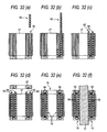
- the procedure is executed as follows. First of all, as shown in Figs. 32 (a) and 32(b) , one of the lid members (end caps) 22 is removed from the slider 16. From the thus opened portion, the rolling element row 62 is inserted into the infinite circulating passage 28. The rolling element row 62 is inserted into the infinite circulating passage 28 until the state shown in Fig. 32(c) can be obtained. In the same manner, as shown in Fig. 32(d) , the rolling element row 62 is successively assembled into each infinite circulating passage 28. As shown in Fig. 32(e) , after the rolling element rows 62 have been assembled into all infinite circulating passages 28, the lid member 22, which was removed before, is attached to the slider body 17. Finally, as shown in Fig. 32(f) , the slider 16, into which the rolling element rows 62 have been assembled, is attached to the guide rail 12.
- Patent Document 6 existence of the end portions of the rolling element accommodating belt, which is formed being provided with end portions, can be a cause of obstructing the smooth operation of the linear guide device. That is, since the rolling element accommodating belt, which is bent in the direction change passage, tends to return to a linear shape, the end portion of the rolling element accommodating belt is abraded with the inner wall of the infinite circulating passage, and the circulating resistance is increased. Further, since the rolling element at the end portion of the rolling element accommodating belt proceeds into a region, in which a load is given to the rolling element, without being drawn by the proceeding rolling element, when the rolling element is moved from the no-load region into the load region, a high circulating resistance is generated.
- Patent Document described above discloses a technique of reducing an increase in the circulating resistance described above, however, as long as the end portion itself is existing, it is difficult to completely eliminate the generation of the circulating resistance.
- the slider 16 is- assembled to the guide rail 12. Due- to the foregoing, for example, as shown in Fig. 32(f) , in a linear guide device having a plurality of rows of the infinite circulating passages, in the case where the number of the rolling elements composing the rolling element row in the infinite circulating passage and the length of the rolling element accommodating belt are the same as those of the rolling element row in the other infinite circulating passage, the phases of the end portions of the rolling element rows coincide with each other in the aligning direction of the infinite circulating passages. Accordingly, a case, in which the end portion of the rolling element accommodating belt and each portion of the infinite circulating passage interfere with each other, substantially simultaneously occurs with respect to all the infinite circulating passages. Accordingly, vibration and noise are more increased-at the time of operation.
- Patent Document 7 discloses a technique in which end portions of the rolling element accommodating belts, which are opposed to each other, are connected with each other.
- end portions of the rolling element accommodating belts which are opposed to each other, are connected with each other.
- the thus connected portion is formed into a special shape with respect to the shape of the other portion. Therefore, even in the case where the end portions are connected to each other, a circulating resistance is generated in the connected end portion which is different from the circulating resistance generated in the other portions. Therefore, when the phases of the infinite circulating passages coincide with each other in the aligning direction, a smooth operation of the linear guide device is obstructed.
- the rolling element accommodating section of the rolling element accommodating belt is composed in such a manner that the rolling element accommodating section allows the accommodated rolling element to come off. Therefore, when the rolling element row of this type rolling element accommodating belt is incorporated into the infinite circulating passage, under the condition that one of the lid members is removed from the slider, while the rolling element accommodating belt is intermittently fed into the infinite circulating passage according to the pitch of the rolling element accommodating sections, the rolling elements are accommodated in the rolling element accommodating section from the thus opened portion. In this way, the rolling element row is composed and inserted. After the rolling element row has been inserted into the infinite circulating passage, the lid member, which was removed before, is attached to the slider body.
- a rolling element accommodating belt according to the preamble of claim 1 is known from EP 0 961 045 A .
- a cage for a radial bearing comprising a plurality of segments each provided with three balls is known from prior art DE 7234477 U . According to this prior art, the central ball only of each segment is restrained from coming off, whereas the other two balls are free to move in the radial direction.
- the teaching of this prior art relates to a rotary bearing.
- At least two types of rolling element accommodating sections described above are composed in such a manner that the degree of restraining the rolling element from coming off of one rolling element accommodating section is lower than that of the other rolling element accommodating section. Therefore, for example, compared with a rolling element accommodating belt in which all rolling element accommodating sections firmly restrain the rolling elements, it is possible to reduce a load of the work in which the rolling elements are incorporated into the rolling element accommodating belt. Further, for example, compared with a rolling element accommodating belt in which all rolling elements are seldom restrained in the directions of both side of the rolling element accommodating belt, the rolling elements can be made to work as a guide of guiding the rolling element accommodating belt in the infinite circulating passage.
- a preferred embodiment of the invention provides a rolling element accommodating belt for a linear guide device according to claim 3, wherein the direction in which the rolling elements are allowed to come off is only one direction at the time of developing in the no-restraint accommodating section.
- the rolling elements are restrained so that they can not come off in the azimuth except for one azimuth. Therefore, for example, at the time of assembling, even when an interval is formed between the slider and the assembling jig, the rolling elements are prevented from coming off.
- a forward end portion of the rolling element accommodating belt can be guided by the rolling elements. Accordingly, there is no possibility that the forward end portion of the rolling element accommodating belt is deflected and blocked when it proceeds. Accordingly, a row of the entire rolling elements formed by the rolling element accommodating belt can be more smoothly guided.
- the number of the no-restraint accommodating sections is larger than the number of the restraint accommodating sections in the rolling element accommodating belt. Therefore, labor needed for assembling the restraint accommodating sections can be reduced.
- a rolling element accommodating belt for a linear guide device characterized in that: the rolling elements can be easily incorporated into the rolling element accommodating belt; and the connecting members of the rolling element accommodating belt can be prevented from wearing. It is also possible to provide a linear guide device having the rolling element accommodating belt.
- Fig. 1 is a perspective view showing a linear guide relating to the first embodiment of the linear guide device into which the rolling element accommodating belt of the present invention is incorporated.
- Fig. 2 is a front view of the linear guide shown in Fig. 1 , wherein an end cap is removed from the linear guide.
- Fig. 3 is a sectional view of the linear guide taken on line X - X in Fig. 2 .
- this linear guide 10 includes: a guide rail 12 having a rolling element guide face 14; and a slider 16 slidably arranged on the guide rail 12 being capable of moving relatively with respect to the guide rail 12.
- the guide rail 12 has a substantially square cross section, and two linear rolling element guide faces 14 are formed on each side of the guide rail 12 in the longitudinal direction, that is, in total, four linear rolling element guide faces 14 are formed on both sides of the guide rail 12 in the longitudinal direction.
- the slider 16 includes: a slider body 17; and a pair of end caps 22, which are lid members and attached to both end portions in the axial direction of the slider body 17.
- Cross sections of the slider body 17 and the end cap 22 in the axial direction are continuously formed into a substantial C-shape.
- a space interposed between the rolling element guide face 14 of the guide rail 12 and the load rolling element guide face 18 of the slider 17, which is opposed to the rolling element guide face 14, composes the rolling element track passage 26.
- a pair of the direction change passages 24, the rolling element return passage 20 and the rolling element track passage 26 compose the infinite circulating passage 28 which annularly continues. In total, four infinite circulating passages 28 are formed.
- a plurality of balls 46 which are the rolling elements, are charged into each infinite circulating passage 28.
- the plurality of balls 46 provided in each infinite circulating passage 28 compose a row of the rolling elements 262 together with the rolling element accommodating belt 250.
- the rolling element accommodating belt 250 includes: two types spacer members 251, 253 which are interposed between the adjoining balls 46 in the infinite circulating passage 28; and a belt-shaped connecting member 252 for connecting the spacer members 251, 253 with each other on both sides in the width direction of the infinite circulating passage 28.
- the rolling element accommodating belt 250 is composed as follows. In a plurality of rolling element accommodating sections (described later) which are defined by the spacer members 251, 253 and the connecting member 252, the balls 46 are individually accommodated at predetermined intervals and aligned into a row of the rolling elements 262 in the infinite circulating passage 28 and maintained so that the balls 46 can be rolled. In this connection, as shown in Fig.
- the rolling element accommodating belt 250- can be guided in such a manner that the connecting member 252 protruding in the width direction in the infinite circulating passage 28 is guided by both sides in the width direction of the groove-shaped guide portion 60 formed in the infinite circulating passage 28 in the slider 16.
- the rolling element accommodating belt 250 will be explained in more detail as follows.
- Fig. 4 is a view for explaining the rolling element accommodating belt.
- Fig. 4(a) is a perspective view showing a state in which the rolling element accommodating belt is developed and extended.
- Figs. 4(b) and 4(c) are partial enlarged views of Fig. 4 (a) for explaining a rolling element accommodating section.
- Fig. 4(d) is a sectional view of the rolling element accommodating section shown in Fig. 4(b) , wherein this view is taken in the direction of aligning the balls.
- the rolling element accommodating belt 250 is formed having end portions.
- the above two types of the spacer members 251, 253 and the connecting members 252 are integrally made of flexible resin material.
- the connecting member 252 is a thin, long belt-shaped member, and the circular ball accommodating hole 255 for accommodating the ball 46 is formed in the longitudinal direction.
- the inner diameter of this ball accommodating hole 255 is determined to be a size so that the ball 46 can be freely engaged with and disengaged from the connecting member 252 in the directions of both sides of the connecting members. That is, the connecting member 252 itself does not have a function of restraining the ball 46 so that the ball 46 can not come off. Under the condition that the rolling element accommodating belt 250 is removed from the slider body 17, the ball 46, which is accommodated in the ball accommodating hole 255 of the connecting member 252, comes off from the ball accommodating hole 255.
- Two types of the spacer members 251, 253 are disk-shaped members, the outer diameters of which are smaller than the outer diameter of the ball 46.
- the restraint spacer member 251 which is one of the two types of the spacer members, has a spherical concave face, which follows a curved face of the ball 46 and is directed to the adjacent ball 46, on one face in the direction in which the balls 46 are aligned in a row.
- the other face of the restraint spacer member 251 is flat.
- the no-restraint spacer member 253, which is the other of the two types of the spacer members has two planes which are respectively directed to the direction in which the adjacent balls 46 are aligned in a row.
- the rolling element accommodating sections there are provided two types according to the degree of restraining the accommodated ball 46 so that the accommodated ball 46 can not come off from the accommodating section. Specifically, one is the restraint accommodating section A in which the ball 46 accommodated in the ball accommodating hole 255 is restrained in all directions, and the other is the no-restraint accommodating section B in which the ball 46 accommodated in the ball accommodating hole 255 is allowed to come off at least in one direction.
- two restraint spacer members 251 are arranged with respect to the ball accommodating hole 255 so that the ball 46 can be interposed between the concave faces 251a, 251b of the restraint spacer members 251 from both sides of the ball 46.
- distance W1 between the opposing restraint spacer members 251 is smaller than diameter D w of the ball 46, and the opening width is smaller than the-ball diameter. Due to the above structure, the ball 46 is restrained in all directions by the restraint spacer members 251, which are adjacent to each other, so that the ball 46 can not come off from the restraint accommodating section A.
- the two no-restraint spacer members 253 are arranged on both sides of the ball 46 with respect to the ball accommodating hole 255.
- distance W2 between the no-restraint spacer members 253, which are opposed to each other is substantially the same as the inner diameter of the ball accommodating hole 255. That is, the opening size of the no-restraint accommodating portion B is larger than the outer diameter of the ball 46. Accordingly, the ball 46 is allowed to come off in the direction of both sides of the belt-shaped connecting member 252. Therefore, the ball 46 can be freely engaged with and disengaged from the accommodating section in the direction of both sides of the connecting member 252 in the no-restraint accommodating section B.
- the spacer member on the restraint accommodating section A side becomes the restraint spacer member 251.
- the restraint spacer member 251 has a concave face only on one face in the direction of aligning the balls 46, and the other face of in the direction of aligning the balls 46 is formed out of the same plane as that of the no-restraint spacer member 253.
- a distance between the restraint spacer member 251 and the no-restraint spacer member 253, which are opposed to each other on the no-restraint accommodating section B side, is equal to distance W2 described before. Therefore, concerning the no-restraint accommodating section B arranged adjacent to the restraint accommodating section A, the ball 46 is allowed to come off in the same manner as that of the other no-restraint accommodating section B.
- the above two types of the rolling element accommodating sections A, B are arranged in a predetermined combination. That is, as shown in Fig. 4 (a) , in this rolling element accommodating belt 250 having end portions, both the end portions are the restraint accommodating sections A described before.
- the restraint accommodating section A is arranged every five accommodating sections in the direction of aligning the balls 46.
- Four portions arranged between the restraint accommodating sections A are composed of the no-restraint accommodating sections B.
- the restraint accommodating section A is arranged every five accommodating sections (i.e., as shown in Fig. 4(a) , the accommodating sections are arranged in order such as A,B,B,B,B,A,B,B,B,B,A...), and at least one restraint accommodating section A is arranged in the linear section in the infinite circulating passage 28 at all times (shown in Fig. 3 ).
- the rolling element accommodating belt 250 is composed as follows. Both end portions of this rolling element accommodating belt 250 are composed of the restraint accommodating sections A as described before, and the restraint accommodating section A is arranged every five accommodating sections. Four accommodating portions arranged between the four restraint accommodating sections A are the no-restraint accommodating sections B.
- the balls 46 are inserted into only the restraint accommodating sections A.
- the same labor as that of the related-art case is needed when the ball 46 is assembled into each restraint accommodating section A.
- the time required for assembling can be reduced as compared with the related-art rolling element accommodating belt having accommodating sections in which the balls are restrained in all directions.
- the rolling element accommodating belt 250 in the restraint accommodating sections A of which the balls 46 are attached, is arranged in the assembling jig 70.
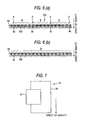
- the balls 46 can be easily inserted into the no-restraint accommodating sections B from the upper portion of the assembling jig 70 as if the balls 46 were made to flow into the no-restraint accommodating sections B. That is, in the no-restraint accommodating sections B, the balls 46 can be easily incorporated into the no-restraint accommodating sections B in the direction in which the balls 46 are allowed to come off. Accordingly, the total time required for assembling is reduced, and as shown in Fig.
- a rolling element row 262 in which the balls 46 are incorporated into the rolling element accommodating belt 250, in the assembling jig 70.
- the rolling element row 262 can be easily charged into the slider 16 from the assembling jig 70.
- Fig 6 is a conceptual view showing a rolling element row circulating in the infinite circulating passage 28.
- Fig. 6(a) is a view showing a rolling element row 262 of this embodiment
- Fig. 6(b) is a view showing a rolling element row (for example, the rolling element row described in the above Patent Document 4), in which the rolling element accommodating sections are composed of the no-restraint accommodating sections B, of Comparative Example.
- the direction of gravity coincides with the thickness direction of the connecting members 252 of the rolling element accommodating belt 250. Therefore, the connecting members 252 is likely to receive an influence of gravity.
- the connecting members 252 are not restrained in the direction of gravity. Therefore, as shown in Fig. 6(b) , the connecting members 252 of the rolling element accommodating belt are strongly rubbed with the guide section 60, which is formed in the slider 16 of the linear guide 10, at all times. Accordingly, there is a possibility that the connecting members 252 are worn out.
- the restraint accommodating section A can restrain positions of the connecting members 252 in the direction of gravity by the balls 46. That is, in the infinite circulating passage 28, the balls 46 in the restraint accommodating sections A function as a guide of the rolling element accommodating belt 250. Therefore, the connecting member 252 is seldom affected by gravity. Accordingly, there is no possibility that only the connecting members 252 are strongly rubbed with the guide sections 60 formed in the slider 16 of the linear guide 10.
- the degree of designing can be extended when the posture of using the linear guide 10 and the posture of assembling the rolling element accommodating belt 250 in the linear guide 10 are designed.
- the conceptual view of Fig. 7 in which an example of the use is shown even when the linear guide 10 is used while the slider 16 is being directed in the longitudinal direction, it is possible to conduct designing without especially giving consideration to a state of contact of the guide portion 60 with the connecting member 252.
- Fig. 8 As a variation of the linear guide 10 is shown in Fig. 8 , even when designing is conducted in such a manner that the thickness direction of the connecting member 252 is inclined with respect to the horizontal face, it is unnecessary to give special consideration to a state of contact of the guide portion 60 with the connecting member 252.
- the reason why the thickness direction of the connecting member 252 is inclined with respect to the horizontal face is that a distance from the center of the rolling element track passage 26 to the center of the rolling element return passage 20 can be extended. When this distance is extended, a radius of changing the direction in the direction change passage 24 can be extended, and the direction of the ball 46 can be more smoothly changed.
- This rolling element accommodating belt 250 is formed being provided with end portions.
- the rolling element accommodating sections located at both end portions are the restraint accommodating sections A. According to the above structure, a forward end portion of the rolling element accommodating belt 250 (rolling element row 262) can be guided by the balls 46. Accordingly, there is no possibility that the forward end portion of the rolling element accommodating belt 250 is deflected and blocked when it proceeds. Accordingly, a row of the entire rolling elements 262 formed by the rolling element accommodating belt 250 can be more smoothly guided.
- the rolling element accommodating belt 250 is composed in such a manner that the restraint accommodating section A is arranged every five accommodating sections, that is, four no-restraint accommodating sections B are arranged between the restraint accommodating sections A. Therefore, the number of the no-restraint accommodating sections B is larger than the number of the restraint accommodating sections A. Due to this structure, labor needed for assembling the balls 46 into the restraint accommodating sections A can be reduced.
- This rolling element accommodating belt 250 is composed in such a manner that at least one restraint accommodating section A is located in the linear portion in the infinite circulating passage 28 at all times. Due to this structure, in the linear portion in the infinite circulating passage 28, the rolling element accommodating belt 250 is guided not only by the connecting members 252 but also by the balls 46 of the restraint accommodating sections A at all times. Therefore, the connecting members 252 can be prevented from wearing, and it becomes possible to provide a more reliable linear guide 10.
- this second embodiment is different from the first embodiment explained above at the point of the structure of the rolling element accommodating belt, and the other points of the structure are the same. Therefore, only the rolling element accommodating belt will be explained here and the other explanations are omitted here.
- the rolling element accommodating belt 80 of the second embodiment is different from that of the first embodiment explained above at the following points of the structure.
- the rolling element accommodating belt 80 of the second embodiment adopts one type spacer member of the substantially U-shaped spacer member 81.
- This spacer member 81 is composed in such a manner that faces of the spacer member 81 directed to the direction of aligning the balls 46 are respectively formed to be a disk-shaped plane, the outer diameter of which is smaller than the outer diameter of the ball 46.
- the spacer member 81 has a substantially U-shaped opening portion which opens from the center of the disk-shaped plane to one of the direct-ions of both sides of the connecting member 252.
- the restraint accommodating section A is composed in such a manner that the substantially U-shaped opening portions of the spacer members 81, which are opposed to each other, are directed to the opposite directions to each other.
- the accommodated ball 46 is held by the inside edges of the spacer members 81 which are opposed to each other. Therefore, the ball 46 is not moved in the direction of the row of the balls. Accordingly, the ball 46 is restrained so that it can not come off from the restraint accommodating section A.
- the no-restraint accommodating section B is composed in such a manner that the directions of the substantially U-shaped opening portions of the spacer members 81 are set to be the same with each other. Therefore, the ball 46 is allowed to come off on the opening side of the substantially U-shaped opening portions of the spacer members 81.
- the azimuth, in which the ball 46 is allowed to come off is set only on the opening side in the developed shape, that is, the azimuth, in which the ball 46 is allowed to come off, is set only in the same azimuth.
- both end portions of the rolling element accommodating belt 80 are composed of the restraint accommodating sections A in the same manner as that of the first embodiment described before.
- two restraint accommodating sections A are respectively, alternately arranged. Accordingly, in the entire rolling element accommodating belt 80, the number of the restraint accommodating sections A and that of the no-restraint accommodating sections B are approximately the same with each other.
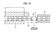
- the no-restraint accommodating section B restrains the ball 46 except for the substantially U-shaped opening side so that the ball 46 can not come off. Accordingly, as shown in Fig. 10 , when the opening side of the no-restraint accommodating section B is set upward at the time of assembling, even if an interval is formed between the slider 16 and the assembling jig 70, it is possible to prevent the ball 46 from falling off. Therefore, it becomes unnecessary to highly accurately position the slider 16 and the assembling jig 70, and the assembling work can be made easy.
- faces of the spacer member 81 which are directed in the direction of aligning the balls 46, are flat. Accordingly, the restraint accommodating section A and the no-restraint accommodating section B can be formed in the direction of both sides of the connecting member 252 while the shapes of the restraint accommodating section A and the no-restraint accommodating section B are being formed without under-cut. Consequently, the rolling element accommodating belt 80 can be easily released from a metallic mold at the time of molding.
- the rolling element accommodating belt for a linear guide device of the present invention and also according to the linear guide device having the rolling element accommodating belt, it is possible to provide a rolling element accommodating belt for a linear guide device in which the rolling elements can be easily incorporated into the rolling element accommodating belt, and the connecting member of the rolling element accommodating belt can be prevented from wearing. It is also possible to provide a linear guide device having the rolling element accommodating belt.
- the rolling element accommodating belt for a linear guide device of the present invention and the linear guide device having the rolling element accommodating belt are not limited to the above specific embodiments. Variations may be made by those skilled in the art without departing from the scope of the present invention.
- the rolling element accommodating belt for a linear guide device of the present invention is applied to the linear guide 10 having the balls 46 which are used as rolling elements.
- the present invention is not limited to this specific embodiment.
- the linear guide device can be applied to a roller guide having rollers which are used as rolling elements.
- Each embodiment described above includes: a restraint accommodating section A in which the ball 46 accommodated in the ball accommodating hole 255 is restrained in all directions so that the ball 46 can not come off; and a no-restraint accommodating section B in which the ball 46 accommodated in the ball accommodating hole 255 is allowed to come off at least in one direction, wherein the restraint accommodating section A and the no-restraint accommodating section B are two types of the rolling element accommodating sections, the degrees of restraining the rolling elements from coming off of which are different from each other.
- the degrees of restraining the rolling elements from coming off are not limited to the above specific embodiment.
- two types of the rolling element accommodating sections may be composed in such a manner that the degree of restraining the rolling elements from coming off of one type may be lower than the degree of restraining the rolling elements from coming off of the other type.
- the opening size is larger than the outer diameter of the ball 46, and the ball 46 is allowed to come off in the direction of both sides of the connecting member 252.
- the opening size may be substantially the same as the outer diameter of the ball 46. Even in this structure, it is easy to incorporate the ball 46 into the no-restraint accommodating section B relatively with the restraint accommodating section A.
- both end portions of the rolling element accommodating belt having end portions are the restraint accommodating sections A.
- the present invention is not limited to this specific example.
- One end portion of the rolling element accommodating belt having end portions may be the restraint accommodating section A.
- both end portions of the rolling element accommodating belt are composed of the restraint accommodating sections.
- the restraint accommodating section A is composed of the spacer members 251, which are opposed to each other, having a concave face.
- the restraint accommodating section A is composed in such a manner that the substantially U-shaped spacer members 81 are used and the directions of the substantially U-shaped opening portions of the spacer members 81, which are opposed to each other, are directed being opposite to each other.
- the shape and combination of the spacer member composing the restraint accommodating section are not limited to each embodiment described above.
- the no-restraint accommodating section B is composed of the flat spacer members 253 which are opposed to each other.
- the no-restraint accommodating section B is composed in such a manner that the directions of the substantially U-shaped opening portions of the spacer members 81 are set in the same direction.
- the shape and combination of the spacer member composing the no-restraint accommodating section are not limited to the above specific embodiment.
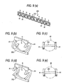
- Fig. 11 is a view showing variations of the shape and combination of the spacer member composing the restraint accommodating section A.
- each spacer member 82 is composed of a combination in which the faces of the spacer members 82 formed on the ball 46 side are a spherical face 82a and a curved face 82b, and the curved face 82b side is an opening portion directed to both sides of the connecting member 252.
- the directions of the opening portions of the spacer members 82, which are opposed to each other, are directed being opposite to each other in the direction of both sides of the connecting member 252. In this way, the restraint accommodating section A is composed.
- the rolling element accommodating section is formed out of a portion defined by the spacer members and the connecting member.
- the rolling element may be formed out of only the ball accommodating hole 255 of the connecting member 252.
- the lip portion 256 is provided on the circumferential wall of the ball accommodating hole 255 of the connecting member 252. This lip portion 256 protrudes in the direction of both sides of the connecting member 252.
- This lip portion 256 is formed while following the spherical face of the ball 46, so that the inner face of this lip portion 256 can allow the ball 46 to rotate.
- This lip portion 256 has a concave face capable of restraining the ball 46 so that the ball 46 can not come off.
- This ball accommodating hole 255 and the lip portion 256 arranged in the periphery of the ball accommodating hole 255 compose the restraint accommodating portion A.
- the spacer members 83 which are opposed to each other, are respectively composed of an annular flat plate.
- the restraint accommodating section A is composed of the spacer members 83 in such a manner that a distance between the spacer members 83, which are opposed to each other, is determined to be a value at which the ball 46 can be rotated on the circumferential edge of the through-hole 83a penetrating the center of the annular shape and the ball 46 can be restrained so that it can not come off.
- each spacer member 84 is composed of a substantially rectangular pawl portion which protrudes in the direction of both sides of the connecting member 252.
- This pawl portion is composed of a curved face 84a opposing to the ball accommodating hole 255.
- the ball 46 is allowed to rotate between the curved faces 84a opposing to each other. Further, these curved faces 84a opposing to each other compose the restraint accommodating portion A capable of restraining the ball 46 so that it can not come off.
- the spacer member 85 is composed of one pawl portion, the shape of which is a substantial rectangle, protruding to one side of the direction of both sides of the connecting member 252 and also composed of the other pawl portion, the shape of which is a substantial rectangle, protruding to the opposite side of the pawl portion.
- Each pawl portion has a curved face 85a directed to the ball accommodating hole 255 side.
- Two curved face 85a are opposed to each other.
- the curved faces 85a of the pawl portions of the spacer members 85 which are opposed to each other, allow the ball 46 to rotate and restrain the ball 46 from coming off. In this way, the restraint accommodating portion A is composed.
- Fig. 12 is a view showing variations of the shape and combination of the spacer member composing the no-restraint accommodating portion B.
- the shape cf the spacer-member 82 is the same as that of the first variation shown in Figs. 11(a) and 11(b) .
- no-restraint accommodating section B is composed.
- the azimuth, in which the ball 46 is allowed to come off is only one of the directions of both sides of the connecting member 252 in the same manner as that of the second embodiment described before.
- the lip portion 256 is provided which has a concave face formed while following the spherical face of the ball 46.
- This lip portion 256 is formed only on one side of the directions of both sides of the connecting member 252.
- the other side of the directions of both sides of the connecting member 252 is open so that it can be larger than the diameter of the ball 46. Therefore, the lip portion 256 of this ball accommodating hole 255 composes the no-restraint accommodating section B to allow the ball 46 to come off on the other side of the directions of both sides of the connecting member 252.
- the spacer member 85 is provided which is formed in the same manner as that of the pawl portion of the fifth variation shown in Figs. 11(i) and 11(j) .
- the pawl portions are protruded to one side (the same side) of the directions of both sides of the connecting member 252. Therefore, the spacer members 85 of this example compose the no-restraint accommodating section B to allow the ball 46 to come off on the other side of the directions of both sides of the connecting member 252.
- no spacer members are used.
- the ball accommodating hole 255 which is composed in the connecting member 252, composes the no-restraint accommodating section B, and the ball 46 is allowed to come off on both sides of the directions of both sides of the connecting member 252.
- the no-restraint accommodating section B is composed of the flat spacer members 253 opposed to each other.
- the ball accommodating hole 86a formed in the connecting member 86 is not a circle but a rectangle which allows the ball 46 to pass through in the directions of both sides of the connecting member 86.
- the shape of the ball accommodating hole is not limited to a circle. It is possible to adopt various shapes.
- the rolling element accommodating section of the present invention can be composed in such a manner that each embodiment and each variation described above are combined with each other.
- a rolling element accommodating belt for a linear guide device having a rolling element accommodating section in which the restraint accommodating section A of the first variation and the no-restraint accommodating section B of the sixth variation are combined with each other.
Landscapes
- Engineering & Computer Science (AREA)
- General Engineering & Computer Science (AREA)
- Mechanical Engineering (AREA)
- Bearings For Parts Moving Linearly (AREA)
- Rolling Contact Bearings (AREA)
Claims (8)
- Wälzkörper-Aufnahmeband (250) für eine lineare Führungsvorrichtung, die einen Endlos-Zirkulationskanal (28) aufweist, in dem eine Vielzahl von Wälzkörpern (46) umlaufend gewälzt werden, wobei das Wälzkörper-Aufnahmeband (250) umfasst:eine Vielzahl von Wälzkörper-Aufnahmeabschnitten (251, 252, 253), die die Wälzkörper (46) einzeln in vorgegebenen Abständen aufnehmen,wobei die Wälzkörper (46) in einer Reihe in dem Endlos-Umlaufkanal (28) ausgerichtet sind und die Wälzkörper (46) dabei in den Wälzkörper-Aufnahmeabschnitten (251, 252, 253) aufgenommen sind, dadurch gekennzeichnet, dass die Wälzkörper-Aufnahmeabschnitte (251, 252, 253) wenigstens zwei Typen (A, B) von Wälzkörper-Aufnahmeabschnitten aufweisen, die sich bezüglich des Grades unterscheiden, in dem die Wälzkörper (46) daran gehindert werden, sich zu lösen.
- Wälzkörper-Aufnahmeband für eine lineare Führungsvorrichtung nach Anspruch 1, wobei die Wälzkörper-Aufnahmeabschnitte einen zurückhaltenden Aufnahmeabschnitt (A) haben, der die aufgenommenen Wälzkörper (46) in allen Richtungen zurückhält, so dass sie sich nicht lösen können, und des Weiteren einen nicht zurückhaltenden Aufnahmeabschnitt (B) aufweisen, der die aufgenommenen Wälzkörper (46) so zurückhält, dass sich die aufgenommenen Wälzkörper (46) in wenigstens einer Richtung lösen können.
- Wälzkörper-Aufnahmeband für eine lineare Führungsvorrichtung nach Anspruch 2, wobei die Richtung, in der sich die Wälzkörper (46) lösen können, während des Abrollens in dem nicht zurückerhaltenden Aufnahmeabschnitt (B) nur eine Richtung ist.
- Wälzkörper-Aufnahmeband für eine lineare Führungsvorrichtung nach Anspruch 2, wobei das Wälzkörper-Aufnahmeband (250) Endabschnitte hat und der Wälzkörper-Aufnahmeabschnitt, der sich in wenigstens einem Endabschnitt des Wälzkörper-Aufnahmebandes (250) befindet, der zurückhaltende Aufnahmeabschnitt (A) ist.
- Wälzkörper-Aufnahmeband für eine lineare Führungsvorrichtung nach Anspruch 2, wobei die Anzahl der nicht zurückhaltenden Aufnahmeabschnitte (B) größer ist als die Anzahl der zurückhaltenden Aufnahmeabschnitte (A).
- Lineare Führungsvorrichtung (10), die umfasst:eine Führungsschiene (12) mit einer Wälzkörper-Führungsfläche (14);einen Schlitten (16), der auf der Führungsschiene (12) angeordnet ist und sich relativ in Bezug auf die Führungsschiene (12) bewegen kann, wobei der Schlitten (16) eine Last-Wälzkörper-Führungsfläche (18) hat, die zusammen mit der Wälzkörper-Führungsfläche (14) einen Wälzkörper-Schienenweg bildet, wobei die Last-Wälzkörper-Führungsfläche (18) der Wälzkörper-Führungsfläche (14) gegenüberliegt, der Schlitten (16) des Weiteren ein Paar Richtungsänderungswege (24) aufweist, die jeweils zu beiden Endabschnitten des Wälzkörper-Schienenweges (14, 18) verlaufen, und der Schlitten (16) des Weiteren einen Wälzkörper-Rückführweg (20) hat, der mit dem Paar Richtungsänderungswege (24) in Verbindung steht;eine Vielzahl von Wälzkörpern (46), die auf einem Endlos-Umlaufweg (28) umlaufen, der aus dem Wälzkörper-Schienenweg (14, 18), dem Paar Richtungsänderungswege (24) und dem Wälzkörper-Rückführweg (20) besteht, wenn die Vielzahl von Wälzkörpern (46) gewälzt werden; undein Wälzkörper-Aufnahmeband (250) für eine lineare Führungsvorrichtung nach Anspruch 1.
- Lineare Führungsvorrichtung (10) nach Anspruch 6 mit einem Wälzkörper-Aufnahmeband (250) für eine lineare Führungsvorrichtung nach Anspruch 2.
- Lineare Führungsvorrichtung nach Anspruch 7, wobei ein oder mehrere zurückhaltende/r Aufnahmeabschnitt/e (A) zu jeder Zeit in einem geradlinigen Abschnitt in dem Endlos-Umlaufweg angeordnet ist/sind.
Priority Applications (1)
| Application Number | Priority Date | Filing Date | Title |
|---|---|---|---|
| EP07005621A EP1801435A3 (de) | 2004-11-11 | 2005-11-11 | Linearführungsvorrichtung und Wälzkörperaufnahmekette dafür |
Applications Claiming Priority (3)
| Application Number | Priority Date | Filing Date | Title |
|---|---|---|---|
| JP2004328095A JP2006138387A (ja) | 2004-11-11 | 2004-11-11 | 直動案内装置用転動体収容ベルトおよび直動案内装置 |
| JP2005021214A JP2006207714A (ja) | 2005-01-28 | 2005-01-28 | 直動案内装置の製造方法および直動案内装置 |
| JP2005120899A JP2006300165A (ja) | 2005-04-19 | 2005-04-19 | リニアガイド装置及びリニアガイド装置用転動体保持器 |
Related Child Applications (1)
| Application Number | Title | Priority Date | Filing Date |
|---|---|---|---|
| EP07005621A Division EP1801435A3 (de) | 2004-11-11 | 2005-11-11 | Linearführungsvorrichtung und Wälzkörperaufnahmekette dafür |
Publications (3)
| Publication Number | Publication Date |
|---|---|
| EP1657459A2 EP1657459A2 (de) | 2006-05-17 |
| EP1657459A3 EP1657459A3 (de) | 2006-08-09 |
| EP1657459B1 true EP1657459B1 (de) | 2008-06-25 |
Family
ID=35985108
Family Applications (2)
| Application Number | Title | Priority Date | Filing Date |
|---|---|---|---|
| EP05024666A Expired - Lifetime EP1657459B1 (de) | 2004-11-11 | 2005-11-11 | Linearwälzlager und Wälzkörperkette dafür |
| EP07005621A Withdrawn EP1801435A3 (de) | 2004-11-11 | 2005-11-11 | Linearführungsvorrichtung und Wälzkörperaufnahmekette dafür |
Family Applications After (1)
| Application Number | Title | Priority Date | Filing Date |
|---|---|---|---|
| EP07005621A Withdrawn EP1801435A3 (de) | 2004-11-11 | 2005-11-11 | Linearführungsvorrichtung und Wälzkörperaufnahmekette dafür |
Country Status (3)
| Country | Link |
|---|---|
| US (1) | US7419302B2 (de) |
| EP (2) | EP1657459B1 (de) |
| DE (1) | DE602005007678D1 (de) |
Families Citing this family (14)
| Publication number | Priority date | Publication date | Assignee | Title |
|---|---|---|---|---|
| US7798718B2 (en) * | 2005-09-29 | 2010-09-21 | Nsk Ltd. | Rolling element accommodating belt for linear guide apparatus and linear guide apparatus |
| EP1873408A2 (de) * | 2006-06-21 | 2008-01-02 | NSK Ltd. | Wälzkörperkette für ein Linearwälzlager, Linearwälzlager und Metallform zum Herstellen einer Wälzkörperkette |
| US7563028B2 (en) * | 2006-09-29 | 2009-07-21 | Hiwin Technologies Corp. | Synchronous spacer with a guiding block |
| US7703981B2 (en) * | 2007-04-11 | 2010-04-27 | Hiwin Technologies Corp. | Linear guideway with a synchronous connector |
| CN101504383B (zh) * | 2009-03-24 | 2012-02-22 | 徐俊峰 | 皮带撕裂监测装置 |
| CN102235423B (zh) * | 2010-04-23 | 2014-03-19 | 上银科技股份有限公司 | 带链条的线性传动组件 |
| US8511897B2 (en) * | 2010-07-08 | 2013-08-20 | Hiwin Technologies Corp. | Linear motion transmission apparatus with a chain |
| CN102174944A (zh) * | 2011-02-23 | 2011-09-07 | 郑广辉 | 轴承及其保持架 |
| US8739416B2 (en) * | 2011-07-25 | 2014-06-03 | Bettcher Industries, Inc. | Power operated rotary knife |
| TWI503490B (zh) * | 2012-09-03 | 2015-10-11 | Chieftek Prec Co Ltd | 保持鏈構造 |
| JP5726922B2 (ja) * | 2013-01-18 | 2015-06-03 | Thk株式会社 | 運動案内装置 |
| JP1586244S (de) * | 2017-05-09 | 2020-09-14 | ||
| TWI691655B (zh) * | 2019-10-01 | 2020-04-21 | 東佑達自動化科技股份有限公司 | 潤滑導管及具潤滑導管的滑台裝置 |
| CN111022496A (zh) * | 2019-12-30 | 2020-04-17 | 智龙传动(厦门)科技有限公司 | 一种静音直线导轨 |
Family Cites Families (21)
| Publication number | Priority date | Publication date | Assignee | Title |
|---|---|---|---|---|
| DE7234477U (de) * | 1972-12-14 | Skf Kugellagerfab Gmbh | Käfig für Wälzlager | |
| JPS6084421A (ja) * | 1983-10-14 | 1985-05-13 | Ichiro Katayama | 摺動台装置用ベアリングユニツト |
| JPH0637893B2 (ja) * | 1987-12-28 | 1994-05-18 | 日本トムソン株式会社 | 四条列無限直動案内ユニット |
| DE4103672C2 (de) * | 1991-02-07 | 1998-11-26 | Schaeffler Waelzlager Ohg | Käfig zur Führung der Wälzkörper eines Umlaufschuhs für eine Linearführung |
| JP2607993B2 (ja) | 1991-08-22 | 1997-05-07 | テイエチケー 株式会社 | ボールチェイン及び直線運動案内装置 |
| JPH05196035A (ja) | 1991-11-22 | 1993-08-06 | Bandou Kiko Kk | 可動支持装置 |
| JPH0672611B2 (ja) * | 1992-01-17 | 1994-09-14 | テイエチケー株式会社 | ボ−ルチェイン |
| JP3447849B2 (ja) | 1995-06-26 | 2003-09-16 | Thk株式会社 | 案内装置の転動体チェーン及びその製造方法 |
| JP3243415B2 (ja) | 1996-06-27 | 2002-01-07 | テイエチケー株式会社 | 摺動案内装置及びその有端転動体チェーン |
| JP3299450B2 (ja) * | 1996-09-13 | 2002-07-08 | テイエチケー株式会社 | 直線運動案内装置およびその転動体チェインの組み込み方法 |
| JP4008066B2 (ja) | 1997-05-16 | 2007-11-14 | Thk株式会社 | 転動体連結体 |
| JP3263005B2 (ja) * | 1997-06-13 | 2002-03-04 | テイエチケー株式会社 | 転がり案内装置 |
| JPH11247854A (ja) * | 1998-02-27 | 1999-09-14 | Thk Co Ltd | 転がり案内装置 |
| DE19824250B4 (de) * | 1998-05-29 | 2012-05-03 | Bosch Rexroth Mechatronics Gmbh | Wälzkörperkette |
| DE19957110A1 (de) * | 1998-05-29 | 2001-05-31 | Rexroth Star Gmbh | Wälzkörperkette Wälzkörperkettenanordnung |
| JP4568453B2 (ja) * | 2000-05-29 | 2010-10-27 | Thk株式会社 | 運動案内装置 |
| JP4365522B2 (ja) * | 2000-10-18 | 2009-11-18 | 日本トムソン株式会社 | セパレータ用連結体を持つ直動案内ユニット |
| DE20101760U1 (de) * | 2001-02-01 | 2002-06-13 | Rexroth Star Gmbh | Wälzkörperkette |
| JP4454192B2 (ja) * | 2001-08-07 | 2010-04-21 | Thk株式会社 | 案内装置の転動体干渉防止具 |
| US6652146B2 (en) * | 2002-03-29 | 2003-11-25 | Mouton Lee | Linear motion guide device having two offset ball rows |
| DE20318163U1 (de) * | 2003-11-24 | 2004-03-11 | Abba Linear Tech Co., Ltd., Tucheng | Ruhige Gleiskette |
-
2005
- 2005-11-11 DE DE602005007678T patent/DE602005007678D1/de not_active Expired - Lifetime
- 2005-11-11 EP EP05024666A patent/EP1657459B1/de not_active Expired - Lifetime
- 2005-11-11 EP EP07005621A patent/EP1801435A3/de not_active Withdrawn
- 2005-11-14 US US11/272,175 patent/US7419302B2/en active Active
Also Published As
| Publication number | Publication date |
|---|---|
| EP1657459A2 (de) | 2006-05-17 |
| EP1801435A3 (de) | 2008-05-14 |
| US20060159373A1 (en) | 2006-07-20 |
| DE602005007678D1 (de) | 2008-08-07 |
| EP1801435A2 (de) | 2007-06-27 |
| EP1657459A3 (de) | 2006-08-09 |
| US7419302B2 (en) | 2008-09-02 |
Similar Documents
| Publication | Publication Date | Title |
|---|---|---|
| EP1657459B1 (de) | Linearwälzlager und Wälzkörperkette dafür | |
| EP0890754B1 (de) | Kugelkette | |
| EP1251287A2 (de) | Linear Wälzführung | |
| JPH1122727A (ja) | 転動体連結体及びこれを用いた直線案内装置並びに転動体ねじ装置 | |
| TWI620884B (zh) | Circulating block and ball screw having the same | |
| TWI700441B (zh) | 滾動引導裝置 | |
| DE102006059161B4 (de) | Lineare Führungsvorrichtung | |
| JP2003506647A (ja) | リニア転がり軸受 | |
| US7980763B2 (en) | Motion guide device | |
| US7121723B2 (en) | Linear guide apparatus | |
| JP2007092898A (ja) | 直動案内装置用転動体収容ベルトおよび直動案内装置 | |
| JP2004068880A (ja) | 直動装置 | |
| JP2006207714A (ja) | 直動案内装置の製造方法および直動案内装置 | |
| JP5169803B2 (ja) | 直動案内装置 | |
| JP4609303B2 (ja) | 直動案内装置およびその製造方法 | |
| JP2008249043A (ja) | 転動体収容ベルトおよび直動案内装置 | |
| JP2003269463A (ja) | 直動装置 | |
| JP4501862B2 (ja) | 転動体収容ベルトおよび直動案内装置 | |
| KR20190127981A (ko) | 볼 수용 밴드 및 운동 안내 장치 | |
| JP2007298117A (ja) | 転動体収容ベルトおよび直動案内装置 | |
| JP4600340B2 (ja) | 転動体収容ベルトおよび直動案内装置 | |
| JP2001099258A (ja) | ボールねじ装置 | |
| JP4556829B2 (ja) | リニアガイド装置 | |
| JP4539574B2 (ja) | 転動体収容ベルトおよび直動案内装置 | |
| JP2006138387A (ja) | 直動案内装置用転動体収容ベルトおよび直動案内装置 |
Legal Events
| Date | Code | Title | Description |
|---|---|---|---|
| PUAI | Public reference made under article 153(3) epc to a published international application that has entered the european phase |
Free format text: ORIGINAL CODE: 0009012 |
|
| AK | Designated contracting states |
Kind code of ref document: A2 Designated state(s): AT BE BG CH CY CZ DE DK EE ES FI FR GB GR HU IE IS IT LI LT LU LV MC NL PL PT RO SE SI SK TR |
|
| AX | Request for extension of the european patent |
Extension state: AL BA HR MK YU |
|
| PUAL | Search report despatched |
Free format text: ORIGINAL CODE: 0009013 |
|
| AK | Designated contracting states |
Kind code of ref document: A3 Designated state(s): AT BE BG CH CY CZ DE DK EE ES FI FR GB GR HU IE IS IT LI LT LU LV MC NL PL PT RO SE SI SK TR |
|
| AX | Request for extension of the european patent |
Extension state: AL BA HR MK YU |
|
| 17P | Request for examination filed |
Effective date: 20060921 |
|
| 17Q | First examination report despatched |
Effective date: 20061020 |
|
| AKX | Designation fees paid |
Designated state(s): DE GB |
|
| GRAP | Despatch of communication of intention to grant a patent |
Free format text: ORIGINAL CODE: EPIDOSNIGR1 |
|
| GRAS | Grant fee paid |
Free format text: ORIGINAL CODE: EPIDOSNIGR3 |
|
| GRAA | (expected) grant |
Free format text: ORIGINAL CODE: 0009210 |
|
| AK | Designated contracting states |
Kind code of ref document: B1 Designated state(s): DE GB |
|
| REG | Reference to a national code |
Ref country code: GB Ref legal event code: FG4D |
|
| REF | Corresponds to: |
Ref document number: 602005007678 Country of ref document: DE Date of ref document: 20080807 Kind code of ref document: P |
|
| PLBE | No opposition filed within time limit |
Free format text: ORIGINAL CODE: 0009261 |
|
| STAA | Information on the status of an ep patent application or granted ep patent |
Free format text: STATUS: NO OPPOSITION FILED WITHIN TIME LIMIT |
|
| 26N | No opposition filed |
Effective date: 20090326 |
|
| GBPC | Gb: european patent ceased through non-payment of renewal fee |
Effective date: 20091111 |
|
| PG25 | Lapsed in a contracting state [announced via postgrant information from national office to epo] |
Ref country code: GB Free format text: LAPSE BECAUSE OF NON-PAYMENT OF DUE FEES Effective date: 20091111 |
|
| PGFP | Annual fee paid to national office [announced via postgrant information from national office to epo] |
Ref country code: DE Payment date: 20191029 Year of fee payment: 15 |
|
| REG | Reference to a national code |
Ref country code: DE Ref legal event code: R119 Ref document number: 602005007678 Country of ref document: DE |
|
| PG25 | Lapsed in a contracting state [announced via postgrant information from national office to epo] |
Ref country code: DE Free format text: LAPSE BECAUSE OF NON-PAYMENT OF DUE FEES Effective date: 20210601 |