EP1659668A2 - Boîtier d'installation pour usage électrotechnique et agencement pour son installation. - Google Patents
Boîtier d'installation pour usage électrotechnique et agencement pour son installation. Download PDFInfo
- Publication number
- EP1659668A2 EP1659668A2 EP05024361A EP05024361A EP1659668A2 EP 1659668 A2 EP1659668 A2 EP 1659668A2 EP 05024361 A EP05024361 A EP 05024361A EP 05024361 A EP05024361 A EP 05024361A EP 1659668 A2 EP1659668 A2 EP 1659668A2
- Authority
- EP
- European Patent Office
- Prior art keywords
- wall
- installation box
- installation
- insulating material
- box
- Prior art date
- Legal status (The legal status is an assumption and is not a legal conclusion. Google has not performed a legal analysis and makes no representation as to the accuracy of the status listed.)
- Granted
Links
Images


Classifications
-
- H—ELECTRICITY
- H02—GENERATION; CONVERSION OR DISTRIBUTION OF ELECTRIC POWER
- H02G—INSTALLATION OF ELECTRIC CABLES OR LINES, OR OF COMBINED OPTICAL AND ELECTRIC CABLES OR LINES
- H02G3/00—Installations of electric cables or lines or protective tubing therefor in or on buildings, equivalent structures or vehicles
- H02G3/02—Details
- H02G3/08—Distribution boxes; Connection or junction boxes
- H02G3/088—Dustproof, splashproof, drip-proof, waterproof, or flameproof casings or inlets
-
- H—ELECTRICITY
- H02—GENERATION; CONVERSION OR DISTRIBUTION OF ELECTRIC POWER
- H02G—INSTALLATION OF ELECTRIC CABLES OR LINES, OR OF COMBINED OPTICAL AND ELECTRIC CABLES OR LINES
- H02G3/00—Installations of electric cables or lines or protective tubing therefor in or on buildings, equivalent structures or vehicles
- H02G3/02—Details
- H02G3/08—Distribution boxes; Connection or junction boxes
- H02G3/12—Distribution boxes; Connection or junction boxes for flush mounting
- H02G3/123—Distribution boxes; Connection or junction boxes for flush mounting in thin walls
Definitions
- the invention relates to an installation box for electrical purposes, in particular hollow wall box, for installation in fire-retardant walls, in particular F-90 walls, wherein the box can be inserted into a matching hole or opening of the wall and fastened in the installed position.
- Installation boxes for electrical purposes, especially hollow wall boxes, are widely known in the art.
- fire-retardant walls which are designed, for example, according to the provisions as F-90 walls
- F-90 protection is not guaranteed.
- the installation boxes themselves not fire retardant according to the provisions are equipped for F- 90 walls and on the other hand both the installation boxes themselves and the wall opening in which these cans are used, can not or only with difficulty be sealed, so that both transmission of fumes and a fire breakthrough before the expiry of the intended time, in particular 90 minutes, is possible.
- the present invention seeks to provide installation boxes of the generic type, which can be installed in fire-retardant walls, in particular F-90 walls, preferably hollow walls, without the fire protection requirements according to standards, directives and / or fire safety regulations, especially according to the F-90 standard, would no longer be guaranteed.
- the can is close to the mouth or at the mouth of a fire-retardant, in particular non-flammable insulating material, which is arranged in the installed position between the hole reveal the perforation of the wall and the can jacket.
- the non-flammable insulating material is a réelleschellendes under flame action or under high temperature, volume enlarging or inflating material.
- the fire-retardant effect is particularly supported because in the event of high temperatures occurring, as occurs in the event of fire, the insulating material swells, increases in volume and / or inflates, so that the passage in the region of the arrangement of the box is increasingly sealed , In an extreme case, when the can softens, the insulating material can even fill the entire hole cross section to ensure the desired fire retardant effect.
- the insulating material is surrounded by a ring of incombustible material, in particular metal, wherein the ring fastening means, in particular fastening straps or the like fasteners, by means of which the ring on the wall, preferably the back, fastened or attached is.
- the material of the wall which often consists of plasterboard, evenly loaded because the expanding in case of fire insulating material is supported evenly between the ring material and the can jacket, so that a uniform surface pressure of the ring material is achieved at the surrounding hole cut the wall ,
- the ring is preferably somewhat elastic and elastic in order to be able to yield and to ensure a tight fit in the perforation.
- the ring fastening straps or the like may be integrally formed on the ring, which can be arranged behind the corresponding wall or on the front side of the corresponding wall and are penetrated by mounting screws in order to realize a fixed arrangement in a simple manner.
- the ring in cross-section U-shaped and between his legs absorbs the insulating material, wherein the insulating material rests on the can jacket.
- the can body which projects beyond the wall in the installed position is covered on the shell side and / or bottom side by insulating material.
- the insulating material is attached to the can body and / or bottom of the can, in particular glued.
- the can body is designed as a multiple box.
- a plaster layer is applied as the insulating material, in particular in the region of the bottom and / or the can jacket projecting from the hole reveal.
- Such a gypsum material layer protects the perforation sufficiently against premature failure and thus against flame breakthrough, wherein, however, insulating material of intumescent or inflating material should nevertheless be provided in the region of the hole reveal.
- the can consists of intumescent material under the influence of temperature.
- a box may be provided alone or in addition to the insulating material. It may be formed in all of the above and in all variants described below in this way.
- An alternative solution of the problem which may also have features of claims 1 to 9, is characterized in that the can with a single wall plate in the region of the hole reveal the perforation of this plate or in the case of multilayer wall plate in the region of the hole reveal of the rear plate is surrounded by a sleeve made of non-flammable material, wherein insulating material, in particular under temperature and / or fire inflating or foaming insulation, is arranged between the sleeve and the box jacket.
- All installation boxes can be used with single-layer wall panels or even with multi-layer wall panels. Depending on whether a single-layer or multi-layer wall plate is used and depending on whether the installation in the new production of the wall is done or provided later, different installation options are given. In any case, at least in the region of a plate, the installation box is surrounded by a collar of incombustible material in the area of the perforated hole reveal. In the space between the sleeve and the can jacket insulating compound is arranged, which can be used for example in the form of ramming mass, or in the form of strips or other molding material. The distance between the sleeve and the can jacket is sufficiently dimensioned so that the desired amount of insulating compound can be introduced.
- the installation can for example be done in such a way that the first cuff is inserted into the corresponding hole of the wall and is attached to this. Subsequently or even before insulating compound in the Cuff are introduced. Subsequently, then the installation box can be inserted into the already fixedly mounted sleeve, wherein the insulating material is supported on the jacket of the box.Bevoryak can be provided that the sleeve is a cross-sectionally U-shaped one-piece, multi-part or flexible ring body, the U - Form is filled with insulating and rests on the can jacket.
- a multi-part or flexible ring body is advantageous because it can first be inserted through the perforation and fixed to the wall, before then the corresponding box in the Cuff is inserted.
- fastening tabs are provided on the sleeve, by means of which the sleeve on the wall plate, preferably on the back or in multi-layer wall plate between the plates, can be fastened.
- fastening tabs or the like can be supported on the back of the wall plate, wherein the fastening is preferably carried out by fastening screws or the like supplied from the front side of the panel, which engage in holes of the mounting tabs and secure them in the desired position.
- the sleeve with insulating material projects beyond the wall on the back.
- the sleeve is designed as a pipe piece, which sits in the hole reveal and the can over its entire length and extends beyond its bottom, insulating between the cuff and the entire jacket of the can and additionally provided outside on the bottom of the can ,
- the box is covered over its entire length of insulating material, but also the bottom can be covered by introduced into the pipe insulating. In addition, it is possible to close the pipe piece or the like with a bottom.
- the sleeve has a bottom part, which is arranged at a distance from the bottom of the can, wherein the entire space between the sleeve and box is filled by insulating.
- a further alternative solution of the object which can also make use of features of claims 1 to 14, is seen in that the can is enveloped by insulating material, in particular refractory material, and that the can with the Isoliermaterialmantel inserted into the perforation of the wall is.
- the entire installation box is already wrapped with insulating material before installation.
- This box thus forms with the insulating material a one-piece, manageable unit that can be used in a suitable manner in the corresponding perforation of the wall and their purpose accordingly prevents a fire breakthrough in the field of perforation.
- the retaining tabs pass through the insulating material and the insulating material allows a shift of the retaining tabs, either by appropriately recessed movement paths or by inherent elasticity of the insulating material.
- the box may for example be equipped with known swing-out retaining tabs that are operable with front-side adjustable screws and are attracted against the back of the wall.
- the box preferably has an edge flange edge, with which it can be supported against the front of the wall. Since the retaining tabs must be able to move according to the suit of the screws in the axial direction of the can, either the insulating material is designed with appropriate movement thread in the region of the tabs or the insulating material is sufficiently intrinsic elasticity, so that it allows the movement of the tabs when tightening the screws.
- a further alternative solution of the object is seen in that a can-like shaped body is provided, which can be inserted into the perforation of the plate and fastened to the plate, that the shaped body made of non-combustible material, preferably metal or ceramic, and is formed in one or more parts in that the shaped body is coated or designed with insulating material on the inside, the insulating material leaving free a blind-hole-like receiving space into which an installation box can be inserted or inserted.
- a can-like shaped body which consists of non-combustible material.
- this shaped body made of sheet metal or ceramic.
- the molded body may be formed in one piece or consist of several parts which are composed.
- On the inside the molded body is coated or designed with insulating compound.
- This shaped body can be secured in a suitable manner, for example by means of the above-described retaining tabs and screws in the region of the perforation of the wall, wherein the shaped body preferably again has a front flange edge, with which it can be supported on the front side of the wall.
- any installation box can be used in this molding. It is not absolutely necessary that the installation box used fully occupied by the insulating still free space, but the can used can maintain distance to the insulating without the desired effect would be affected in case of fire.
- a counter-pressure bearing is formed in case of fire, so that the can closes inwards when the insulating material increases in temperature due to the volume.
- the invention further relates to an arrangement for installation of installation boxes for electrical purposes, in particular cavity wall boxes, in openings of fire-retardant walls, in particular F- 90 walls, wherein the installation box can be inserted into the breakthrough and fixed in the installation target position.
- Installation boxes for electrical purposes, in particular cavity wall boxes are known in the art.
- fire-retardant walls which are designed, for example, according to the provisions as F-90 walls
- F-90 protection is not guaranteed. This may be due to the fact that the installation boxes themselves are not fire-retardant according to the provisions for F-90 walls and also that the installation boxes themselves and also the wall opening into which the boxes are inserted are not or only with difficulty sealed may or may, so that both the transmission of fumes and a
- the present invention seeks to provide an assembly for the installation of installation boxes, by the installation in fire-retardant walls, in particular F-90 walls, preferably hollow walls is possible without the fire protection requirements according to standards, guidelines and / or fire safety regulations, in particular according to the F-90 standard, would no longer be guaranteed.
- the invention proposes that a molded body made of elastically deformable insulating material is provided, which is either inserted into the wall breakthrough and is supported on the hole reveal the breakthrough, or is inserted through the wall breakthrough and the back of the breakthrough Wall supports, and that the molded body has a cavity open on one side, in which an installation box is inserted or used.
- a molded body made of elastically deformable insulating material is provided.
- a wall opening is first generated, which is used to insert the Shaped body and / or an installation box is suitable and intended. Subsequently, then, the shaped body can be inserted into the wall opening, so that an end portion of the shaped body is supported on the hole reveal of the opening. Subsequently, in the open to the front of the corresponding wall cavity of the molding body, an installation box can be used and fixed.
- the installation box may preferably be a so-called hollow wall box.
- the diameter of the shaped body is slightly larger than the corresponding wall opening, so that the shaped body can be used with elastic deformation in this wall breakthrough and supported by the inherent elasticity of the hole reveal the Wandungs bebruches.
- a shaped body which is considerably larger in diameter or in the transverse dimension than the wall opening.
- This shaped body can then be pushed through appropriate deformation through the opening and installed, so that the molded body is arranged completely behind the corresponding wall.
- suitable measures are provided to support the molding on the back of the wall or to fix.
- an installation box preferably a cavity wall box.
- the molded body consists of elastic insulating material which is not or hardly inflammable, fire-retardant, swelling under flame or high temperature, cooling, volume enlarging and / or inflatable.
- the installation box has lug bearings and mouth side stop parts or a stop edge, the installation box with the stop parts or the stop edge is supported on the front of the wall and by means of the rear side of the wall, attractable to this lug bearings in the Fixing target position is fixed.
- the installation box in the cavity of the molding is adhesively, positively, frictionally engaged or detent.
- the molding is adhered to the back of the wall.
- the molded body in particular when it is inserted through the wall breakthrough, at least provisionally or permanently fixed to the back of the wall, so that it is held captive.
- a blind installation can be done so that, for example, the molding is indeed installed, the frontal mouth but is covered by a cover, which is only removed when an installation box to be inserted into the cavity of the molding.
- the shaped body in particular on the bottom side, has at least one push-through area for cables or similar connection means, which due to the elasticity of the shaped body is self-closing or in which the material of the molding self-sealingly applied to the jacket of inserted cables or the like connection means.
- the molded body preferably consists of such material which can be pierced with a tool or directly with a cable, wherein the elasticity of the material should be sufficient to ensure a self-sealing contact of the shaped body with the cable jacket when a cable or the like is inserted. If the shaped body has corresponding apertures through which a cable or the like can be pushed, they are self-closing, that is, the material of the molded body closes these openings due to its inherent elasticity and only releases a gap when inserting a cable or the like in turn self-sealing is sealed by the material of the shaped body.
- connection cables or the like can then be inserted into the corresponding installation box before the installation box is finally inserted into the cavity of the molding.
- a holding element is formed, which can be mounted through the wall opening and is fixed to an end area at the hole reveal or in its area, wherein the holding element in the beyond Wall breakthrough lying region has a larger transverse dimension than the transverse dimension or the diameter of the wall breakthrough corresponds, and that is inserted into the holding element of the molded body made of elastically deformable insulating material and held by this, wherein the shaped body has a larger transverse dimension or a larger diameter than the wall breakthrough, wherein in addition the molded body is supported on the rear wall of this and has a one-sided open cavity for receiving a through the wall opening supplied installation box.
- a holding element which can be inserted through the wall breakthrough and is fixed with an end portion of the hole reveal or in the area.
- the holding element is preferably deformable in such a way that, in spite of its larger transverse dimension, it corresponds to the dimension of the wall opening, is compressible and can be fed through the wall opening, wherein, for example due to the Its own elasticity spreads with its end area in the area of the hole reveal and is clamped in the hole reveal.
- the molded body which preferably also consists of elastically deformable insulating material, can then be mounted and inserted through the wall opening, wherein the molded body is held and supported by the holding element.
- the molded body or its cavity is preferably dimensioned so that the molded body is supported at the rear of the wall of this and the cavity of the molded body is aligned approximately flush with the hole reveal the Wandungs bebruches.
- an installation box can be supplied, which is then enclosed by the molding.
- the retaining element For fastening the retaining element can be provided that the retaining element is clipped into the wall opening, snapped, glued and / or screwed.
- the holding element is designed as a two-armed or multi-arm springing bracket.
- the resilient strap is approximately U-shaped and is formed at its leg ends in the manner of a locking profile, which in the assembly target position in sits the hole reveal and the edge of the recess of the plate on the front and rear overlaps.
- the shaped body forms a unit firmly connected to the holding element.
- the molded body on stable holding parts which may not consist of the material of the molding, but of other material and allow secure mounting and fixing of the molded part in the hole reveal or in the area of the hole reveal the Wandungs exercisebruches.
- the holding parts are designed as L-shaped fittings, one leg of which is connected to the molding and on the front protrudes from this and the other leg on the front of the wall is applied -in Montagagesolllage-.
- the holding parts are clipped on the molding, locked, molded, glued and / or screwed.
- a preferred alternative solution to the problem is that a bag-like part is arranged in the wall breakthrough or on an inserted into the wall breakthrough installation box near the wall, which arranged in the wall opening and back of the Surrounds wall projecting installation box, and that in the sack-like part is in components located in the assembly position insulating compound is injected, which forms between the jacket and the bottom of the installation box and the bag-like part filled with insulating protective jacket.
- a bag-like part which forms an outer shell for the later to be introduced insulating compound.
- This bag-like element can be fed through the wall breakthrough and secured in a suitable manner in the region of the wall breakthrough on the wall or on the installation box.
- the baggy part has preferably such a dimension that between the jacket and the bottom of the installation box and the bag-like part sufficient
- Free space is formed can be introduced into the insulating.
- the bag-like part can first be positioned and arranged in the correct position before the installation box is inserted into the bag-like part. Subsequently, then insulating material between the outer shell and the bottom of the installation box and the bag-like part can be injected, so that the cavity between these parts is filled and insulation is ensured to a sufficient extent. It is also possible to install the installation box together with the bag-like part held thereon, that is to introduce into the corresponding wall opening. Every night is then injected, for example, through an opening of the installation box insulating material in the space between the outer shell of the installation box and the bottom and the surrounding bag-like part to form a sufficient protective jacket.
- the insulating material is a foamable, volume-increasing MehrComponent material.
- Such so-called two-component materials are known per se, wherein the two components during injection by means of a Cartridge or the like are mixed, whereby the corresponding chemical reaction is generated, which leads to a foaming and an increase in volume of the mixed material, so that a good filling of the cavity to be filled between the installation box and bag-like part is achieved.
- the installation box has in the shell and / or in the bottom injection openings for introducing insulating in the cavity between the installation box and the bag-like part.
- the bag-like part has at its mouth a flange forming parts or an annular flange.
- the bag-like part has a mounting bracket, in particular with external sawtooth contour, which engages in mounting desired position in the hole reveal the Wandungs bebruches.
- the bag-like part consists of non-dimensionally stable material or material combinations, in particular of Fabrics, foil, nets knitted fabric, woven fabric, fabric or combinations thereof.
- the bag-like part consists of dimensionally stable material or combinations of materials, in particular latticework, perforated material, preferably metallic films, meshes, fabrics, knitted or laid.
- the bag-like part consists of a combination of dimensionally stable and non-dimensionally stable materials or material combinations.
- the installation box has lug bearings and mouth side stop members or a stop edge, the bag-like part is fixed by means of the tab bearing in the desired mounting position and / or between the jacket of the installation box and the hole reveal of Wall breakthrough is held clamped.
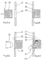
- the drawing shows arrangements of an installation box for electrical purposes, namely a hollow wall box for installation in fire-retardant walls, which are equipped in particular according to the provisions as F-90 walls.
- the walls are plates 1, for example made of plasterboard, the plates can be arranged simply or in multiple layers.
- these plates 1 have a perforation, in which a corresponding box can be used.
- the can 2 is surrounded at the mouth of a non-flammable insulating material 3, which is arranged in the installation target position, as shown in particular in Figure 1, between the Lochlaibung the perforation of the wall 1 and the can jacket of the box 2 is.
- the fire-retardant, in particular non-flammable insulating material 3 is preferably a material that expands under the action of flame or under high temperature, volume-enlarging or inflatable material.
- the insulating material 3 is surrounded by a ring 4 of incombustible material, for example metal.
- This ring 4 has fastening tabs 5 or similar fastening parts, by means of which the ring 4 on the wall 1, preferably on the back, attached can be.
- For fastening serve corresponding screws 6, which are fed from the front of the wall 1 and screwed through corresponding holes of the tabs 5.
- the ring 4 may have a U-shaped cross section so that the insulating material is received between the base and the legs of the U-shaped ring.
- the insulating material is supported on the jacket of the box 2.
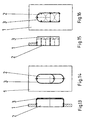
- the can body 2 protruding beyond the wall in the installed position is covered on the shell side with insulating material 7 and on the bottom side with insulating material 8.
- This insulating material 7 and 8 may be attached to the can body or on the bottom of the can, for example, be glued.
- the can body can also be designed as a multiple can. As a rule, such can bodies are circular in cross section. Only in the multiple arrangement, an oval shape or a multi-constricted round shape is common.
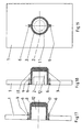
- FIGS. 7 to 10 the arrangement of a corresponding installation box 2 in the case of single-layer wall panels (FIG. 8) and multilayer wall panels (FIGS. 7 and 9) is shown.
- the perforation of this panel and in the case of a multilayer wall panel is preferably in the region of Lochlabung the rear plate, a collar 4 of incombustible material disposed surrounding the body of the can 2.
- a collar 4 of incombustible material disposed surrounding the body of the can 2.
- Between the sleeve 4 and the can jacket insulating compound 3 is arranged, which preferably inflates under temperature and / or fire action, foams or the like volume-increasing property.
- the sleeve 4 is a cross-sectionally U-shaped one-piece, multi-part or bendable ring body, wherein the U-shape of the sleeve 4 is filled with insulating compound 3, which is supported on the can jacket.
- fastening tabs 5 are again provided on the sleeve 4, by means of which the sleeve 4 can be fastened to the rear side of the wall panel according to FIG. 8 or between the wall panels according to FIGS. 7 and 9.
- screws 6 are used which can be actuated from the front of the plate.
- the sleeve 4 can be arranged and secured in the correct position with insulating compound. Subsequently, the can 2 can be inserted into the prepared cuff.
- the sleeve 4 is designed as a tubular piece which sits in the hole reveal and encompasses the socket 2 over its entire length and also projects beyond its bottom. Between the sleeve 4 and the entire jacket of the box and in addition also outside on the bottom of the can insulating 3 is provided.
- the cuff could be 4 be closed at the end by a bottom part, which is arranged at a distance from the bottom of the can 2.
- the box 2 itself is enveloped by insulating material 3, wherein the insulating material 3 in turn made of refractory material, possibly also under the action of fire and temperature influence aufblähbarem material.
- the box can be prefabricated with an insulating material jacket of insulating material 3 and used in this form in the corresponding perforation of the wall 1.
- the attachment takes place by means of known retaining tabs 9 and screws 10, as is known in hollow wall boxes per se.
- the sheath of insulating material 3 is formed so that a movement path for the displacement of the retaining tabs 9 is generated, or the insulating material 3 is designed so that it releases the way for the movement of the retaining tabs 9 by inherent elasticity.
- FIGS. 17 to 19 a can-like shaped body 11 is provided, which is insertable into the corresponding perforation of the plate 1 and is fastened by means of fastening straps or the like to the plate.
- the molding 11 consists of incombustible material, such as metal or ceramic. In turn, it may be formed in one piece or also in several parts.
- the molded body 11 is designed or coated with insulating compound 3, wherein the insulating compound leaves a blind-hole-like receiving space 12 free.
- an installation box 2 can be used, as illustrated in Figure 18.
- the lined with insulating compound 3 shaped body can be inserted and pre-assembled in a corresponding hole. It is subsequently possible to insert a suitable box into the corresponding receiving space 12 and fix it in a suitable manner.
- FIGS. 20A to 20D are arrangements for the installation of installation boxes 22 for electrical purposes, in particular cavity wall boxes, shown in apertures 24 of fire-retardant walls 21, wherein the walls may consist of einlagigem or multilayer material.
- a shaped body 23 is made of elastically deformable material Insulating arranged.
- two variants are shown, wherein in each case in the upper half of the drawing figure, a first molded body 23 and in the lower half of a second molded body 23 is shown.
- a molded body 23 which is shown only halfway in the drawing figures 20A to 20D, it is likewise compressed during installation and pushed through the wall opening 24. Subsequently, the shaped body is positioned behind the wall, as shown in Figure 20C and 20D upper half of the figure.
- the molded body 23 has a front open cavity, which is intended for installation of an installation box 22. After the arrangement of the molded body 23 on the wall 21, the installation box 22 can be inserted and plugged into the cavity, as illustrated in Figure 20D.
- the installation box 22 may have tab bearings 55 which by means of a screw 26 of the Front of the mounting hole forth are actuated, the installation box 22 additionally front stop parts or a circumferential stop edge, which is supported on the front side of the wall 21. In a manner known per se, so that the installation box can be permanently installed in the wall breakthrough.
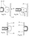
- a holding element 27 is provided, which is elastically deformable and can be mounted through the wall opening 24.
- the assembly is illustrated by the sequence of figures 21A, 21B and 21C.
- holding element 27 In the end position, holding element 27, as shown in FIGS. 21C and 21D, has an end region on hole reveal 24, wherein the holding element has a larger transverse dimension in the region beyond wall breakthrough 24 than wall breakthrough 24.
- Holding element 27 is in turn Shaped body 23 inserted from elastically deformable insulating material and held by this.
- the shaped body 23 also has a larger transverse dimension than the wall opening 24.
- the assembly of the shaped body 23 can be seen with reference to the sequence of FIGS. 21A to 21D.
- the molded body 23 In the end position, the molded body 23 is supported at the rear of the wall 21 adjacent to the wall opening 24, wherein the shaped body 23 in turn has a cavity open on one side in the wall opening 24 Receiving a through the wall opening 24 supplied installation box 22 has.
- the holding element 27 is formed as a resilient strap, which is approximately U-shaped and to his
- the molded body 23 can also form a firmly connected unit with the holding element 27.
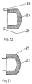
- the shaped body 23 can also preferably have holding parts 28 on the front side, which rest in the desired mounting position on the hole reveal of the wall opening 4 and on the front side of the wall 21.
- the holding parts 28 are formed as L-shaped fittings, one leg of which is connected to the molding 23 and protrudes from the front of this, while the other leg rests in the mounting target position on the front side of the wall 21.
- the holding parts 28 may be attached to the molding 23 in any manner.
- FIG. 23 shows a variant in which the molded part 23 is firmly connected to the retaining element 27.
- a bag-like part 29 is arranged in the wall opening 24 according to the embodiment according to FIG. 24 or on an installation box 22 inserted into the wall opening 24 of the embodiment according to FIG. 25, that is arranged in the wall opening 24 and at the back side of FIG the wall 21 protruding installation box 22 surrounds.
- Insulating compound 30 is injected into the bag-like part 29 when parts are in a position to be installed, which is shown only partially in FIG. 24D, FIG. 25B and FIG. 26B, not in the form of a mold.
- the insulating material 30 is supplied in such an amount that the space between the shell and the bottom of the installation box 22 and the bag-like part 29 is completely filled with insulating and thus forms a protective sheath.
- the feeding of the insulating compound 30 can take place by means of a cartridge 31, by means of which a multi-component material can be supplied, which foams up and increases considerably in volume.
- the installation box 22 may have openings in the jacket and / or in the bottom through which insulating material can be fed into the cavity by means of the cartridge 31.
- the bag-like part 29 has at its mouth a flange-forming part 32 or an annular flange which rests against the outside of the wall 21 in the desired mounting position.
- the bag-like part 29 has a mounting bracket 33 with external sawtooth contour, which engages in mounting desired position according to Figure 26B in the hole reveal the Wandungs tellbruches 24 and ensures a secure fit.
- This element is elastically deformable so that it can be fed in a position shown in FIG. 26A and then spread open in order to assume the desired position according to FIG. 26B.
- the installation box 22 is essentially held only by the insulating compound 30 in its assembly target position after the ready installation.
- the installation box 22 in turn has tab bearings 25 with actuating screws 26, as well as a stop collar on the outlet side, as is known per se in the prior art, in order to achieve a secure fit in the wall opening 24.
- the bag-like part 29 can be held clamped between the hole reveal of the wall opening 24 and the jacket of the installation box 22 located there.
Landscapes
- Engineering & Computer Science (AREA)
- Architecture (AREA)
- Civil Engineering (AREA)
- Structural Engineering (AREA)
- Connection Or Junction Boxes (AREA)
- Casings For Electric Apparatus (AREA)
- Installation Of Indoor Wiring (AREA)
Applications Claiming Priority (2)
| Application Number | Priority Date | Filing Date | Title |
|---|---|---|---|
| DE202004018083U DE202004018083U1 (de) | 2004-11-22 | 2004-11-22 | Installationsdose für elektrotechnische Zwecke |
| DE200520004106 DE202005004106U1 (de) | 2005-03-11 | 2005-03-11 | Anordnung zur Installation von Installationsdosen für elektrotechnische Zwecke |
Publications (3)
| Publication Number | Publication Date |
|---|---|
| EP1659668A2 true EP1659668A2 (fr) | 2006-05-24 |
| EP1659668A3 EP1659668A3 (fr) | 2010-03-03 |
| EP1659668B1 EP1659668B1 (fr) | 2011-08-17 |
Family
ID=35883539
Family Applications (1)
| Application Number | Title | Priority Date | Filing Date |
|---|---|---|---|
| EP05024361A Expired - Lifetime EP1659668B1 (fr) | 2004-11-22 | 2005-11-09 | Boîtier d'installation pour usage électrotechnique et agencement pour son installation. |
Country Status (2)
| Country | Link |
|---|---|
| EP (1) | EP1659668B1 (fr) |
| AT (1) | ATE521115T1 (fr) |
Cited By (4)
| Publication number | Priority date | Publication date | Assignee | Title |
|---|---|---|---|---|
| ITVI20110088A1 (it) * | 2011-04-08 | 2012-10-09 | Belfiore S R L | Supporto portafrutti per pareti in cartongesso |
| EP2597743A1 (fr) * | 2011-11-23 | 2013-05-29 | Schneider Electric Danmark A/S | Ensemble de montage pour le montage d'un dispositif d'installation électrique |
| DE102014108551B3 (de) * | 2014-06-17 | 2015-08-27 | Svt Brandschutz Vertriebsgesellschaft Mbh International | Brandschutz für Hohlwanddosen |
| FR3039332A1 (fr) * | 2015-07-21 | 2017-01-27 | Ian Frederic Leo Moore | Pot de scellement specifique a la necessite d'etancheite a l'air |
Family Cites Families (4)
| Publication number | Priority date | Publication date | Assignee | Title |
|---|---|---|---|---|
| DE7734966U1 (de) * | 1977-11-15 | 1978-08-10 | Schimmeister, Erwin, 3253 Hessisch Oldendorf | Installationsdose, insbesondere zum Einbau in Wände mit leicht entflammbarer Bespannung |
| DE2806374C3 (de) * | 1978-02-13 | 1980-08-21 | Eternit Ag, 1000 Berlin | Hohlwanddose für Elektroinstallationen |
| DE2834189A1 (de) * | 1978-08-04 | 1980-02-14 | Rigips Baustoffwerke Gmbh | Hohlwanddose, insbesondere fuer elektrische installationen |
| GB2345125B (en) * | 1998-12-23 | 2002-05-01 | Tenmat Ltd | Intumescent downlighter cover and method of manufacturing same |
-
2005
- 2005-11-09 AT AT05024361T patent/ATE521115T1/de active
- 2005-11-09 EP EP05024361A patent/EP1659668B1/fr not_active Expired - Lifetime
Cited By (4)
| Publication number | Priority date | Publication date | Assignee | Title |
|---|---|---|---|---|
| ITVI20110088A1 (it) * | 2011-04-08 | 2012-10-09 | Belfiore S R L | Supporto portafrutti per pareti in cartongesso |
| EP2597743A1 (fr) * | 2011-11-23 | 2013-05-29 | Schneider Electric Danmark A/S | Ensemble de montage pour le montage d'un dispositif d'installation électrique |
| DE102014108551B3 (de) * | 2014-06-17 | 2015-08-27 | Svt Brandschutz Vertriebsgesellschaft Mbh International | Brandschutz für Hohlwanddosen |
| FR3039332A1 (fr) * | 2015-07-21 | 2017-01-27 | Ian Frederic Leo Moore | Pot de scellement specifique a la necessite d'etancheite a l'air |
Also Published As
| Publication number | Publication date |
|---|---|
| EP1659668A3 (fr) | 2010-03-03 |
| ATE521115T1 (de) | 2011-09-15 |
| EP1659668B1 (fr) | 2011-08-17 |
Similar Documents
| Publication | Publication Date | Title |
|---|---|---|
| EP4043080B1 (fr) | Collier de protection contre l'incendie | |
| EP2587106B1 (fr) | Manchette pare-feu | |
| EP3289265B1 (fr) | Manchette coupe-feu | |
| EP2466178A1 (fr) | Module pare-feu | |
| DE19960485A1 (de) | Brandschutzmanschette für Rohre, Kabel u. dgl. | |
| DE19852120C2 (de) | Intumeszierende Brandschutzvorrichtung zum Abschotten von durch Wände oder Decken durchgeführten Rohren | |
| EP3460930B1 (fr) | Boîtier d'installation pour l'installation électrique | |
| EP2030653B1 (fr) | Dispositif de passage de câble doté d'une protection anti-incendie | |
| EP2273639A2 (fr) | Boîtier d'installation électrique | |
| DE102014108551B3 (de) | Brandschutz für Hohlwanddosen | |
| DE29704346U1 (de) | Brandschutzeinrichtung für durch Wände und/oder Decken eines Gebäudes geführte Leitungen einer Klima- und/oder Be- bzw. Entlüftungsanlage | |
| EP2081268A1 (fr) | Dispositif doté d'un canal pour câble | |
| EP1362961A1 (fr) | Elément de construction pour la protection coupe-feu d' un dispositif d' écoulement et dispositif d'écoulement comprenant un tel élement | |
| EP1659668A2 (fr) | Boîtier d'installation pour usage électrotechnique et agencement pour son installation. | |
| EP3289267B1 (fr) | Manchette coupe-feu | |
| DE102006001644B4 (de) | Verfahren zur Brandsicherung von Durchführungen | |
| BE1017293A6 (de) | Intumeszierende elektrische installationsteile. | |
| DE10201287C5 (de) | Bodenablauf | |
| DE202004018083U1 (de) | Installationsdose für elektrotechnische Zwecke | |
| DE102012025094B4 (de) | Brandschutzmanschette | |
| EP1705304A2 (fr) | Panneau coupe-feu de plafond, paroi ou plancher | |
| DE202005004106U1 (de) | Anordnung zur Installation von Installationsdosen für elektrotechnische Zwecke | |
| EP1491702B1 (fr) | Trappe de visite | |
| EP1791236B1 (fr) | Boîtier d'installation électrique | |
| DE102021124092A1 (de) | Installationsdose sowie Intumeszenzeinsatz dafür |
Legal Events
| Date | Code | Title | Description |
|---|---|---|---|
| PUAI | Public reference made under article 153(3) epc to a published international application that has entered the european phase |
Free format text: ORIGINAL CODE: 0009012 |
|
| AK | Designated contracting states |
Kind code of ref document: A2 Designated state(s): AT BE BG CH CY CZ DE DK EE ES FI FR GB GR HU IE IS IT LI LT LU LV MC NL PL PT RO SE SI SK TR |
|
| AX | Request for extension of the european patent |
Extension state: AL BA HR MK YU |
|
| PUAL | Search report despatched |
Free format text: ORIGINAL CODE: 0009013 |
|
| AK | Designated contracting states |
Kind code of ref document: A3 Designated state(s): AT BE BG CH CY CZ DE DK EE ES FI FR GB GR HU IE IS IT LI LT LU LV MC NL PL PT RO SE SI SK TR |
|
| AX | Request for extension of the european patent |
Extension state: AL BA HR MK YU |
|
| RIC1 | Information provided on ipc code assigned before grant |
Ipc: H02G 3/08 20060101ALI20100127BHEP Ipc: H02G 3/12 20060101AFI20060306BHEP |
|
| 17P | Request for examination filed |
Effective date: 20100807 |
|
| 17Q | First examination report despatched |
Effective date: 20101013 |
|
| AKX | Designation fees paid |
Designated state(s): AT BE BG CH CY CZ DE DK EE ES FI FR GB GR HU IE IS IT LI LT LU LV MC NL PL PT RO SE SI SK TR |
|
| GRAP | Despatch of communication of intention to grant a patent |
Free format text: ORIGINAL CODE: EPIDOSNIGR1 |
|
| GRAS | Grant fee paid |
Free format text: ORIGINAL CODE: EPIDOSNIGR3 |
|
| GRAA | (expected) grant |
Free format text: ORIGINAL CODE: 0009210 |
|
| AK | Designated contracting states |
Kind code of ref document: B1 Designated state(s): AT BE BG CH CY CZ DE DK EE ES FI FR GB GR HU IE IS IT LI LT LU LV MC NL PL PT RO SE SI SK TR |
|
| REG | Reference to a national code |
Ref country code: GB Ref legal event code: FG4D Free format text: NOT ENGLISH |
|
| REG | Reference to a national code |
Ref country code: CH Ref legal event code: EP Ref country code: CH Ref legal event code: NV Representative=s name: TROESCH SCHEIDEGGER WERNER AG |
|
| REG | Reference to a national code |
Ref country code: IE Ref legal event code: FG4D Free format text: LANGUAGE OF EP DOCUMENT: GERMAN |
|
| REG | Reference to a national code |
Ref country code: DE Ref legal event code: R096 Ref document number: 502005011766 Country of ref document: DE Effective date: 20111027 |
|
| REG | Reference to a national code |
Ref country code: NL Ref legal event code: VDEP Effective date: 20110817 |
|
| LTIE | Lt: invalidation of european patent or patent extension |
Effective date: 20110817 |
|
| PG25 | Lapsed in a contracting state [announced via postgrant information from national office to epo] |
Ref country code: FI Free format text: LAPSE BECAUSE OF FAILURE TO SUBMIT A TRANSLATION OF THE DESCRIPTION OR TO PAY THE FEE WITHIN THE PRESCRIBED TIME-LIMIT Effective date: 20110817 Ref country code: PT Free format text: LAPSE BECAUSE OF FAILURE TO SUBMIT A TRANSLATION OF THE DESCRIPTION OR TO PAY THE FEE WITHIN THE PRESCRIBED TIME-LIMIT Effective date: 20111219 Ref country code: IS Free format text: LAPSE BECAUSE OF FAILURE TO SUBMIT A TRANSLATION OF THE DESCRIPTION OR TO PAY THE FEE WITHIN THE PRESCRIBED TIME-LIMIT Effective date: 20111217 Ref country code: SE Free format text: LAPSE BECAUSE OF FAILURE TO SUBMIT A TRANSLATION OF THE DESCRIPTION OR TO PAY THE FEE WITHIN THE PRESCRIBED TIME-LIMIT Effective date: 20110817 Ref country code: NL Free format text: LAPSE BECAUSE OF FAILURE TO SUBMIT A TRANSLATION OF THE DESCRIPTION OR TO PAY THE FEE WITHIN THE PRESCRIBED TIME-LIMIT Effective date: 20110817 Ref country code: LT Free format text: LAPSE BECAUSE OF FAILURE TO SUBMIT A TRANSLATION OF THE DESCRIPTION OR TO PAY THE FEE WITHIN THE PRESCRIBED TIME-LIMIT Effective date: 20110817 |
|
| PG25 | Lapsed in a contracting state [announced via postgrant information from national office to epo] |
Ref country code: SI Free format text: LAPSE BECAUSE OF FAILURE TO SUBMIT A TRANSLATION OF THE DESCRIPTION OR TO PAY THE FEE WITHIN THE PRESCRIBED TIME-LIMIT Effective date: 20110817 Ref country code: LV Free format text: LAPSE BECAUSE OF FAILURE TO SUBMIT A TRANSLATION OF THE DESCRIPTION OR TO PAY THE FEE WITHIN THE PRESCRIBED TIME-LIMIT Effective date: 20110817 Ref country code: PL Free format text: LAPSE BECAUSE OF FAILURE TO SUBMIT A TRANSLATION OF THE DESCRIPTION OR TO PAY THE FEE WITHIN THE PRESCRIBED TIME-LIMIT Effective date: 20110817 Ref country code: GR Free format text: LAPSE BECAUSE OF FAILURE TO SUBMIT A TRANSLATION OF THE DESCRIPTION OR TO PAY THE FEE WITHIN THE PRESCRIBED TIME-LIMIT Effective date: 20111118 Ref country code: CY Free format text: LAPSE BECAUSE OF FAILURE TO SUBMIT A TRANSLATION OF THE DESCRIPTION OR TO PAY THE FEE WITHIN THE PRESCRIBED TIME-LIMIT Effective date: 20110817 |
|
| REG | Reference to a national code |
Ref country code: IE Ref legal event code: FD4D |
|
| PG25 | Lapsed in a contracting state [announced via postgrant information from national office to epo] |
Ref country code: SK Free format text: LAPSE BECAUSE OF FAILURE TO SUBMIT A TRANSLATION OF THE DESCRIPTION OR TO PAY THE FEE WITHIN THE PRESCRIBED TIME-LIMIT Effective date: 20110817 Ref country code: CZ Free format text: LAPSE BECAUSE OF FAILURE TO SUBMIT A TRANSLATION OF THE DESCRIPTION OR TO PAY THE FEE WITHIN THE PRESCRIBED TIME-LIMIT Effective date: 20110817 Ref country code: IE Free format text: LAPSE BECAUSE OF FAILURE TO SUBMIT A TRANSLATION OF THE DESCRIPTION OR TO PAY THE FEE WITHIN THE PRESCRIBED TIME-LIMIT Effective date: 20110817 |
|
| PG25 | Lapsed in a contracting state [announced via postgrant information from national office to epo] |
Ref country code: IT Free format text: LAPSE BECAUSE OF FAILURE TO SUBMIT A TRANSLATION OF THE DESCRIPTION OR TO PAY THE FEE WITHIN THE PRESCRIBED TIME-LIMIT Effective date: 20110817 Ref country code: EE Free format text: LAPSE BECAUSE OF FAILURE TO SUBMIT A TRANSLATION OF THE DESCRIPTION OR TO PAY THE FEE WITHIN THE PRESCRIBED TIME-LIMIT Effective date: 20110817 Ref country code: RO Free format text: LAPSE BECAUSE OF FAILURE TO SUBMIT A TRANSLATION OF THE DESCRIPTION OR TO PAY THE FEE WITHIN THE PRESCRIBED TIME-LIMIT Effective date: 20110817 |
|
| PLBE | No opposition filed within time limit |
Free format text: ORIGINAL CODE: 0009261 |
|
| STAA | Information on the status of an ep patent application or granted ep patent |
Free format text: STATUS: NO OPPOSITION FILED WITHIN TIME LIMIT |
|
| PG25 | Lapsed in a contracting state [announced via postgrant information from national office to epo] |
Ref country code: DK Free format text: LAPSE BECAUSE OF FAILURE TO SUBMIT A TRANSLATION OF THE DESCRIPTION OR TO PAY THE FEE WITHIN THE PRESCRIBED TIME-LIMIT Effective date: 20110817 Ref country code: MC Free format text: LAPSE BECAUSE OF NON-PAYMENT OF DUE FEES Effective date: 20111130 |
|
| 26N | No opposition filed |
Effective date: 20120521 |
|
| GBPC | Gb: european patent ceased through non-payment of renewal fee |
Effective date: 20111117 |
|
| REG | Reference to a national code |
Ref country code: DE Ref legal event code: R097 Ref document number: 502005011766 Country of ref document: DE Effective date: 20120521 |
|
| PG25 | Lapsed in a contracting state [announced via postgrant information from national office to epo] |
Ref country code: GB Free format text: LAPSE BECAUSE OF NON-PAYMENT OF DUE FEES Effective date: 20111117 |
|
| PG25 | Lapsed in a contracting state [announced via postgrant information from national office to epo] |
Ref country code: ES Free format text: LAPSE BECAUSE OF FAILURE TO SUBMIT A TRANSLATION OF THE DESCRIPTION OR TO PAY THE FEE WITHIN THE PRESCRIBED TIME-LIMIT Effective date: 20111128 |
|
| PG25 | Lapsed in a contracting state [announced via postgrant information from national office to epo] |
Ref country code: LU Free format text: LAPSE BECAUSE OF NON-PAYMENT OF DUE FEES Effective date: 20111109 |
|
| PG25 | Lapsed in a contracting state [announced via postgrant information from national office to epo] |
Ref country code: BG Free format text: LAPSE BECAUSE OF FAILURE TO SUBMIT A TRANSLATION OF THE DESCRIPTION OR TO PAY THE FEE WITHIN THE PRESCRIBED TIME-LIMIT Effective date: 20111117 |
|
| PG25 | Lapsed in a contracting state [announced via postgrant information from national office to epo] |
Ref country code: TR Free format text: LAPSE BECAUSE OF FAILURE TO SUBMIT A TRANSLATION OF THE DESCRIPTION OR TO PAY THE FEE WITHIN THE PRESCRIBED TIME-LIMIT Effective date: 20110817 |
|
| PG25 | Lapsed in a contracting state [announced via postgrant information from national office to epo] |
Ref country code: HU Free format text: LAPSE BECAUSE OF FAILURE TO SUBMIT A TRANSLATION OF THE DESCRIPTION OR TO PAY THE FEE WITHIN THE PRESCRIBED TIME-LIMIT Effective date: 20110817 |
|
| REG | Reference to a national code |
Ref country code: FR Ref legal event code: PLFP Year of fee payment: 11 |
|
| REG | Reference to a national code |
Ref country code: FR Ref legal event code: PLFP Year of fee payment: 12 |
|
| REG | Reference to a national code |
Ref country code: FR Ref legal event code: PLFP Year of fee payment: 13 |
|
| PGFP | Annual fee paid to national office [announced via postgrant information from national office to epo] |
Ref country code: FR Payment date: 20231121 Year of fee payment: 19 Ref country code: CH Payment date: 20231208 Year of fee payment: 19 Ref country code: AT Payment date: 20231122 Year of fee payment: 19 |
|
| PGFP | Annual fee paid to national office [announced via postgrant information from national office to epo] |
Ref country code: BE Payment date: 20231121 Year of fee payment: 19 |
|
| PGFP | Annual fee paid to national office [announced via postgrant information from national office to epo] |
Ref country code: DE Payment date: 20240130 Year of fee payment: 19 |
|
| REG | Reference to a national code |
Ref country code: DE Ref legal event code: R119 Ref document number: 502005011766 Country of ref document: DE |
|
| REG | Reference to a national code |
Ref country code: CH Ref legal event code: PL |
|
| REG | Reference to a national code |
Ref country code: AT Ref legal event code: MM01 Ref document number: 521115 Country of ref document: AT Kind code of ref document: T Effective date: 20241109 Ref country code: CH Ref legal event code: PL |
|
| PG25 | Lapsed in a contracting state [announced via postgrant information from national office to epo] |
Ref country code: CH Free format text: LAPSE BECAUSE OF NON-PAYMENT OF DUE FEES Effective date: 20241130 |
|
| PG25 | Lapsed in a contracting state [announced via postgrant information from national office to epo] |
Ref country code: AT Free format text: LAPSE BECAUSE OF NON-PAYMENT OF DUE FEES Effective date: 20241109 |
|
| REG | Reference to a national code |
Ref country code: BE Ref legal event code: MM Effective date: 20241130 |
|
| PG25 | Lapsed in a contracting state [announced via postgrant information from national office to epo] |
Ref country code: DE Free format text: LAPSE BECAUSE OF NON-PAYMENT OF DUE FEES Effective date: 20250603 |
|
| PG25 | Lapsed in a contracting state [announced via postgrant information from national office to epo] |
Ref country code: BE Free format text: LAPSE BECAUSE OF NON-PAYMENT OF DUE FEES Effective date: 20241130 |
|
| PG25 | Lapsed in a contracting state [announced via postgrant information from national office to epo] |
Ref country code: FR Free format text: LAPSE BECAUSE OF NON-PAYMENT OF DUE FEES Effective date: 20241130 |