EP1659672A1 - Stator pour machine électrique, methode pour réaliser un stator et moteur à courant continu - Google Patents
Stator pour machine électrique, methode pour réaliser un stator et moteur à courant continu Download PDFInfo
- Publication number
- EP1659672A1 EP1659672A1 EP05016715A EP05016715A EP1659672A1 EP 1659672 A1 EP1659672 A1 EP 1659672A1 EP 05016715 A EP05016715 A EP 05016715A EP 05016715 A EP05016715 A EP 05016715A EP 1659672 A1 EP1659672 A1 EP 1659672A1
- Authority
- EP
- European Patent Office
- Prior art keywords
- stator
- sleeve
- teeth
- stator teeth
- slots
- Prior art date
- Legal status (The legal status is an assumption and is not a legal conclusion. Google has not performed a legal analysis and makes no representation as to the accuracy of the status listed.)
- Granted
Links
- 238000004519 manufacturing process Methods 0.000 title claims abstract description 6
- 238000000034 method Methods 0.000 title claims description 6
- 230000005291 magnetic effect Effects 0.000 claims abstract description 29
- 239000003302 ferromagnetic material Substances 0.000 claims abstract description 5
- 239000000463 material Substances 0.000 claims description 26
- 238000004804 winding Methods 0.000 claims description 16
- 230000005298 paramagnetic effect Effects 0.000 claims description 13
- 230000005294 ferromagnetic effect Effects 0.000 claims description 10
- 238000010438 heat treatment Methods 0.000 claims description 8
- 239000012777 electrically insulating material Substances 0.000 claims description 6
- 239000000956 alloy Substances 0.000 claims description 4
- 229910045601 alloy Inorganic materials 0.000 claims description 4
- 239000000057 synthetic resin Substances 0.000 claims description 2
- 229920003002 synthetic resin Polymers 0.000 claims description 2
- 230000008901 benefit Effects 0.000 description 9
- 229910052751 metal Inorganic materials 0.000 description 8
- 239000002184 metal Substances 0.000 description 8
- 238000003466 welding Methods 0.000 description 8
- 230000004048 modification Effects 0.000 description 6
- 238000012986 modification Methods 0.000 description 6
- 241000209035 Ilex Species 0.000 description 5
- 230000006698 induction Effects 0.000 description 4
- 230000015572 biosynthetic process Effects 0.000 description 3
- 230000004907 flux Effects 0.000 description 3
- 239000000696 magnetic material Substances 0.000 description 3
- 238000004080 punching Methods 0.000 description 3
- 238000000926 separation method Methods 0.000 description 3
- 229910000831 Steel Inorganic materials 0.000 description 2
- 238000004026 adhesive bonding Methods 0.000 description 2
- 239000011324 bead Substances 0.000 description 2
- 230000000694 effects Effects 0.000 description 2
- 238000007885 magnetic separation Methods 0.000 description 2
- 150000002739 metals Chemical class 0.000 description 2
- 230000035699 permeability Effects 0.000 description 2
- 239000010959 steel Substances 0.000 description 2
- RYGMFSIKBFXOCR-UHFFFAOYSA-N Copper Chemical compound [Cu] RYGMFSIKBFXOCR-UHFFFAOYSA-N 0.000 description 1
- 230000009471 action Effects 0.000 description 1
- 230000004323 axial length Effects 0.000 description 1
- UQMRAFJOBWOFNS-UHFFFAOYSA-N butyl 2-(2,4-dichlorophenoxy)acetate Chemical compound CCCCOC(=O)COC1=CC=C(Cl)C=C1Cl UQMRAFJOBWOFNS-UHFFFAOYSA-N 0.000 description 1
- 230000000295 complement effect Effects 0.000 description 1
- 238000013461 design Methods 0.000 description 1
- 238000010292 electrical insulation Methods 0.000 description 1
- 238000002474 experimental method Methods 0.000 description 1
- 230000002349 favourable effect Effects 0.000 description 1
- 238000003780 insertion Methods 0.000 description 1
- 230000037431 insertion Effects 0.000 description 1
- 238000009413 insulation Methods 0.000 description 1
- 238000003475 lamination Methods 0.000 description 1
- 238000002844 melting Methods 0.000 description 1
- 230000008018 melting Effects 0.000 description 1
- 239000000203 mixture Substances 0.000 description 1
- 229910052759 nickel Inorganic materials 0.000 description 1
- 238000005457 optimization Methods 0.000 description 1
- 239000000088 plastic resin Substances 0.000 description 1
- 238000003825 pressing Methods 0.000 description 1
- 230000009467 reduction Effects 0.000 description 1
Images


Classifications
-
- H—ELECTRICITY
- H02—GENERATION; CONVERSION OR DISTRIBUTION OF ELECTRIC POWER
- H02K—DYNAMO-ELECTRIC MACHINES
- H02K3/00—Details of windings
- H02K3/46—Fastening of windings on the stator or rotor structure
- H02K3/48—Fastening of windings on the stator or rotor structure in slots
- H02K3/487—Slot-closing devices
- H02K3/493—Slot-closing devices magnetic
Definitions
- the invention relates to a stator assembly for an electric machine, a method for manufacturing a stator assembly, and a DC motor using such a stator assembly.
- the stator arrangement according to the invention can be used in a wide variety of types of electrical machines and is provided in particular for DC motors and generators.
- a preferred field of application of the invention are brushless DC motors and other permanent magnet motors, which are preferably configured as internal rotor motors.
- Electric motors with a permanent magnetic internal rotor configuration have a rotor return, which is applied to a shaft, wherein one or more permanent magnets are applied to the rotor yoke or embedded in these.
- the motors include a stator assembly which is typically constructed of a number of packetized metal sheets forming an annular stator yoke from which stator teeth project radially inwardly. The stator teeth form the stator poles, between which stator slots for receiving windings are formed.
- the rotor assembly is coaxially inserted into the stator assembly.
- the invention is also applicable to external rotor motors.
- stator and stator are housed in a housing having at least one end flange for mounting the motor.
- the outer side of the stator lamination stack closes the motor to the outside.
- stator consists of a grooved laminated core, with the windings, for example of insulated copper wire, being received in the slots of the stator.
- stator teeth are widened at their free ends and have so-called pole pieces, which serve to absorb as much magnetic flux as possible and reduce the detent torque of the machine by their design.
- the pole pieces have the additional function of winding the coils inside the slots fix their position.
- To reduce the cogging torque of an electrical machine and to optimize the magnetic flux pole shoes should be as wide as possible.
- a disadvantage of wide pole shoes is that they leave only a relatively narrow gap open for passing the winding wire into the stator slots.
- stator arrangement having the features of patent claim 1.
- the invention also provides a DC motor according to claim 11 and a method for producing a stator assembly for an electrical machine according to claim 12.
- the invention provides a stator assembly for an electric machine and in particular for a DC motor, which has a stator body with a stator yoke ring and a plurality of stator teeth.
- the stator teeth extend radially from the stator return ring and define stator slots between them to receive windings.
- Stator poles are formed at the free ends of the stator teeth.
- the stator assembly is for an internal rotor motor, the stator teeth extending radially inwardly from the stator yoke ring in this configuration.
- the stator teeth have no widening pole shoes at their free ends, as would be customary in the prior art.
- stator assembly After winding the stator teeth, a sleeve is applied to the stator assembly according to the invention, which extends coaxially to the stator and is coupled to the free ends of the stator teeth. In an internal rotor configuration, the sleeve determines the inner diameter of the stator and closes it off from the rotor.
- the sleeve has several functions in the stator assembly according to the invention. First, it serves as a slot cover and holds the windings in the stator slots. For this feature is it is expedient to coat the sleeve on its surface facing the stator grooves with an electrically insulating material, so that it also assumes the function of a slot insulation. Another more important function of the sleeve is the formation of pole pieces. To achieve this object, the sleeve is expediently made of a ferromagnetic material, wherein it is magnetically coupled to the free ends of the stator teeth.
- the sleeve is preferably designed so that it has between each two adjacent stator teeth in the axial direction extending non-weak or weak magnetic zones to magnetically separate the pole pieces of adjacent stator teeth from each other.
- These zones between the pole shoes can be narrow because they only have the function of magnetically separating the pole pieces.
- the zones for separating the pole pieces are formed by narrow slots formed from the sleeve, e.g. be punched out.
- the sleeve is preferably made of ferromagnetic material in this embodiment.
- the sleeve is made of a bi-permeable material which is ferromagnetic in a first state and paramagnetic in a second state.
- This material has ferromagnetic properties in its initial state and paramagnetic properties after heat treatment.
- the sleeve is locally heated in the area in which the non-magnetic or weakly magnetic zones are to be formed and thus brought into the paramagnetic state within these zones.
- a material suitable for making the sleeve according to the invention is an Fe-Cr-C based alloy manufactured by Hitachi Metals Ltd., Tokyo, Japan under the name YEP FA1 steel.
- This alloy is described, for example, in US Pat. Nos. 6,255,005 and 6,390,443, and Japanese Patent Laid-Open Publication Nos. 2004-091842, JP 2004143585 and JP 2004-281737.
- These publications are related to the composition of the bi-permeable material as well as those disclosed therein Temperature ranges, particularly temperatures for converting the bi-permeable material from the ferromagnetic to the paramagnetic state.
- the bi-permeable material in electromagnetic valves and used other magnetic components; use in stator arrangements is neither described nor intended.
- the sleeve is also coated on its surface remote from the stator slots with electrically insulating material to provide electrical insulation from the rotor, e.g. to avoid voltage flashovers in the event of a fault.
- the stator assembly according to the invention can be produced in a particularly simple and cost-effective manner, when the sleeve is made from a stamped, rolled and optionally coated sheet metal.
- the sleeve is first punched from a flat sheet, with slots for the separation of the individual pole pieces and recesses for connection with the stator teeth are mitausgestanzt. Subsequently, the sheet is rolled into a sleeve which is open at a seam and thus flexible. This facilitates the application or pressing of the sleeve on the free ends of the stator teeth. It is expedient to provide the free ends of the stator teeth with a corresponding fit, which cooperates with the recesses in the sleeve.
- the recesses for connection to the stator teeth may be formed by slots extending in the axial direction along the sleeve which are closed at both axial ends of the sleeve. In this embodiment, the recesses are pressed onto the stator teeth. In an alternative embodiment, the recesses are formed by slots which are closed at only one axial end of the sleeve. In this embodiment, the sleeve can be pushed in the axial direction of the stator or the stator teeth.
- lateral slots are formed in the stator teeth near their free ends to slid the sleeve in the axial direction onto the stator teeth so that the edges of the recesses engage in the slots.
- the sleeve In its second embodiment, the sleeve, similar to the first embodiment, is stamped from a flat sheet, this sheet being made of the bi-permeable material of the type described above. Recesses for connecting the sleeve with the stator teeth are punched with, but slots for the separation of the individual poles of the stator are not necessary. Subsequently, the sheet is rolled into a sleeve which is open at a seam and thus flexible. The sleeve can be pushed onto the stator teeth in the axial direction or pressed onto them.
- the sleeve Before or after the sleeve is applied to the stator teeth, preferably before the sheet is rolled into a sleeve, it is locally heated within the axially extending zones, each between two adjacent stator teeth, about the bi-permeable material within it To convert zones from the ferromagnetic initial state to the paramagnetic state.
- the zones are preferably heated to a temperature> 1150 °, for example by means of laser or induction welding. While this second embodiment requires the additional operation of localized heating of the sleeve, it has the advantage that the sleeve has better mechanical stability compared to the slotted sleeve. Magnetic short circuits in the region of the front end of the sleeve, on which the slots are bridged in the first embodiment, can be avoided.
- stator assembly In order to stabilize the finished stator assembly, it can be encapsulated with a plastic or synthetic resin.
- the sleeve itself can also be stiffened by beads or folds.
- the sleeve generates a certain amount of eddy currents, this effect being less in the embodiment with the slots than in the embodiment in which the sleeve is made of the bi-permeable material.
- the problem of eddy current formation can be minimized in that the sleeve is constructed from individual mutually electrically insulated layers, similar to the production of a stator body from a stamped sheet stack.
- a series of sheets of ferromagnetic material or of the bi-permeable material are stacked and punched into narrow sheet metal strips. Then the sheets are joined together.
- the sheets are made of the bi-permeable material, it is advisable to bring the sheets in the zone by heat treatment, for example by means of laser or induction welding, in a paramagnetic state and simultaneously to connect within these areas. Subsequently, the recesses for pushing the sleeve on the stator teeth are removed, for example, punched out, and the sleeve is rolled and optionally joined together at their ends.
- the advantage of this arrangement is that due to the sheet structure eddy currents within the sleeve material are virtually completely avoided.
- At least one axial end of the sleeve projects beyond a front end of the stator body in the axial direction.
- This embodiment has the advantage that the webs arranged at the axial ends, which hold the sleeve together and bridge the pole shoes, can be arranged outside the magnetic field of the rotor. This prevents that the sleeve forms a magnetic short circuit in the region of the rotor.
- Another advantage of a sleeve projecting in the axial direction over at least one front end of the stator body is that it shields stator magnetic fields toward the rotor.
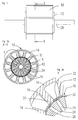
- Fig. 1 shows an external view of a DC motor according to the invention.
- a stator 10 can be seen, in which a sleeve 12 is applied to the stator teeth, which projects axially at both ends of the stator 10.
- the stator body 10 includes a stator return ring 14 from which stator teeth 16 extend inwardly in the radial direction.
- the stator teeth are coupled at their free ends to the sleeve 12.
- the sleeve has slot-shaped recesses 18 which are engaged with the free ends of the stator teeth 16, wherein in the illustrated embodiment, the stator teeth 16 have at their free ends a connecting portion 20 which is pressed or pushed into the recesses 18.
- the sleeve further has slots 22, which are arranged approximately in the middle between two adjacent recesses 20 and associated stator teeth 16.
- the sleeve may be stiffened by beads or folds or the like (not shown).
- the sleeve 12 protrudes in the axial direction in relation to the front ends of the stator body 10. It delimits the stator body 10 against a rotor space.
- a rotor Coaxially within the stator body 10, a rotor is arranged, which is shown schematically by a rotor body 24 in the figures.
- the rotor body 24 has spoke-shaped recesses 26 for receiving permanent magnets, the recesses 26 being connected in pairs.
- the rotor body 24 is applied to a shaft 28. Between the rotor body 24 and the stator body 10, a working air gap 30 is formed.
- stator teeth 16 are substantially rectangular without the broadening of their free ends common in the prior art to form pole pieces. This allows a simple winding of the stator body 10, because the slot opening between two adjacent pole teeth 16 is very far. Alternatively, it is possible to postpone already pre-wound coils together with bobbin from the inside to the stator teeth 16.
- the sleeve 12 is applied after the winding of the stator teeth 16 on the free ends and thus also serves as a groove cover. Suitably, it is coated on its surface facing the stator with an electrically insulating material.
- the sleeve 12 is made of a ferroelectric material and magnetically coupled to the stator teeth.
- the sleeve 12 forms the pole pieces at the end of the stator teeth 16, with adjacent pole pieces being separated by the slots 22 formed in the sleeve.
- a stator arrangement with pole shoes can be produced whose slot opening is smaller than is usual in the prior art.
- the rule is that the slot opening must be about ⁇ 1.5 times the wire diameter, which must be passed through the slot opening. This limitation does not have to be complied with in the stator arrangement according to the invention. This results in a stator that achieves extremely low torque fluctuations and a relatively high flux concentration during operation.
- the sleeve 12 is preferably formed so that it protrudes at the axial ends of the stator body 10. This has the advantage that the axial, the slots 22 bridging webs 34, which are necessary for the cohesion of the sleeve, are outside the range of action of the rotor and thus can not form a magnetic short circuit. Furthermore, the sleeve 22 at the front end of the stator assembly 10 shields the magnetic field generated by the stator in the direction of the rotor. Magnetic sensors for detecting the rotational position of the electrical machine, for example, Hall sensors or magnetoresistive sensors, are often arranged on the stator or on the flange opposite the front side of the rotor.
- these are preferably arranged in the vicinity of the outer circumference of a rotor. This is especially the case when the rotor is not, as in the embodiment shown, embedded permanent magnets but the permanent magnets are arranged on the outer circumference of the rotor. Nearby However, the circumference of the rotor also affects the magnetic field generated by the winding head, which is largely shielded in the invention by the axial projecting sleeve 12.
- a possible position for a rotational position sensor is indicated by the arrow S.
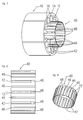
- the sleeve 12 may be coated on its inside and / or its outside with an electrically insulating material.
- the sleeve is preferably punched out of a metal sheet and then rolled, wherein the sleeve 12 can remain open at a seam 32.
- the sleeve 12 is sufficiently flexible to introduce it in the axial direction in the interior of the stator body 10 and press with the recesses 18 on the stator teeth 16.
- the geometry of the free ends of the stator teeth 16 and the recesses 18 must be suitably adapted to each other.
- the recesses 18 and the slots 22 are bridged at both axial ends of the sleeve 12 by webs 34.
- the recesses 18 at one axial end of the sleeve 12 are open. This makes it possible for the sleeve 12 to be pushed onto the stator teeth 16 in the axial direction.
- the slots 22 are open at one axial end of the sleeve, whereby the risk of the formation of a magnetic short circuit through the sleeve 12 is reduced. It can also be provided to separate the sleeve 12 after application to the stator teeth 16 in the region of the slots 22 in order to completely separate adjacent pole pieces for magnetic optimization.
- stator assembly may be appropriate to encase the wound stator assembly after applying the sleeve 12 with a plastic in order to increase the stability of the stator assembly.
- the separation of the sleeve 12 may take place after the stator assembly has been embedded in plastic.
- Fig. 6 shows a schematic sectional view through a section of an electric machine according to another embodiment of the invention, which is similar to Fig. 2b. Corresponding parts are denoted by the same reference numerals and not explained again in detail.
- the stator teeth 16 in the vicinity of their free ends on lateral grooves 36, in which the sleeve 12 - in axial Direction of the stator - can be inserted.
- the recesses 18 of the sleeve 12 are open at one end to insert the sleeve 12 with the edges of the recesses 18 in the slots 36.
- This embodiment has the advantage that the sleeve can not be pulled off the stator teeth or poles as a result of the magnetic attraction of the rotor magnets.
- the sleeve is preferably made of a magnetically conductive, i. ferromagnetic, material. However, if it is only intended to fulfill the function of a slot cover, it can also be made of a non-magnetic material.
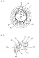
- FIG. 7 to 9 A second embodiment of the stator assembly according to the invention is shown in Figs. 7 to 9 and a modification of this embodiment in Figs. 10a and 10b.
- this embodiment does not differ from that described above.
- Corresponding parts are identified by the same reference numerals.
- the sleeve is constructed differently than in the first embodiment.
- the sleeve 40 is made of a magnetic material which is ferromagnetic in a first state and paramagnetic in a second state.
- This magnetic material is also referred to as a bi-permeable material.
- the preferred material for the sleeve according to the second embodiment is a YEP FA1 steel developed by Hitachi Metals Ltd., Tokyo, Japan. This is an alloy based on Fe-Cr-C, which additionally contains amounts of Si, Mn, Ni or Al. This material has a starting ferromagnetic state with a relative magnetic permeability of about 900 and a paramagnetic state with a relative magnetic permeability as low as 1.01.
- the material can be converted from the ferromagnetic to the paramagnetic state by heating it to a temperature above 1050 ° C, especially above 1100 ° C, preferably in the range of 1100 ° C and 1200 ° C.
- a particularly preferred temperature range is between 1150 ° C and the melting temperature of the material.
- the entire sleeve 40 is made of this material, wherein the sleeve is preferably punched out of a sheet and recesses 42 are formed during the punching. Subsequently, the sleeve is rolled, wherein it can initially remain open at a seam 44. The sleeve 40 is slid with the recesses 42 on the stator teeth 16 in the axial direction, as described above with reference to the first embodiment. Alternatively, the sleeve 40 can also be pressed onto the stator teeth 16.
- the sleeve 40 is locally heated in the region of axially extending zones 46, whereby the sleeve 40 is brought in the region of these zones 46 in the paramagnetic state.
- the zones 46 are selected to provide complete magnetic separation of the individual stator poles formed by the stator teeth 16 and the adjacent portions of the sleeve 40, the zones 46 each being symmetrical between two adjacent stator poles.
- the heating can be generated for example by means of laser or induction welding, which is preferably of the order of 1150 ° C.
- the heating of the zones 46 of the sleeve 40 can be done before or after the roll of the sleeve; it is preferably done before.
- the sleeve is preferably formed so as to protrude at the axial ends of the stator body 10.
- the webs 48 at the ends of the sleeve 40 which bridge the recesses 42 and are necessary for the cohesion of the sleeve, also heated and thereby converted into the paramagnetic state. In this way, magnetic short circuits in this area can be completely avoided.
- the sleeve 40 may be coated on its inside with an electrically insulating material.
- the recesses 42 are bridged by the webs 48 only at one axial end of the sleeve 40.
- the recesses 42 could be provided that the recesses 42 are bridged at both axial ends of the sleeve 40 in order to give the sleeve additional stability. In this case, it would not be possible to push the sleeve on the stator body 10 in the axial direction, but the sleeve could be pressed onto the stator teeth 16 from the inside. It may be appropriate to encase the wound stator assembly after applying the sleeve 40 with a plastic to increase the stability of the stator assembly.
- the sleeve 40 is slid onto an axial end of the stator body 10.
- a modification of this embodiment is shown in Figs. 10a to 10b, wherein in this modification, the sleeve is constructed in two parts, so that it can be pushed from the two opposite axial ends of the stator 10.
- the two sleeve halves 40 'of the two-part sleeve can basically be constructed in the same way as the one-part sleeve 40 shown in FIGS. 8 and 9, wherein the sleeve is only shortened in the axial direction so as to push the two halves 40' on both sides of the stator body. that they complement each other to a sleeve which extends substantially over the entire axial length of the stator.
- a gap 50 between the sleeve halves 40 ' is shown, they are preferably as far pushed onto the stator body 10 that they touch at their front ends, whereby a small gap is tolerable.
- the second embodiment has the advantage of increased mechanical stability as well as complete magnetic separation of the individual poles of the stator assembly. However, it generates eddy currents to some extent, which can be suppressed by the measures described below.
- the sleeve is constructed of individual mutually electrically insulated layers.
- sheets of bi-permeable material are preferably stacked and stamped into sheet metal strips, which are initially designed linear and serve as a base for the sleeve.
- the areas which are to form the demagnetized zones are demagnetized by heat treatment, for example by means of laser or induction welding, and at the same time the individual sheets are thereby connected to one another.
- the recesses for pushing the sleeve on the stator teeth are removed, for example by punching, and the sleeve is rolled and possibly joined together at their ends. Due to the sheet metal structure of the sleeve eddy currents can be avoided within the sleeve material.
Landscapes
- Engineering & Computer Science (AREA)
- Power Engineering (AREA)
- Iron Core Of Rotating Electric Machines (AREA)
- Manufacture Of Motors, Generators (AREA)
Priority Applications (2)
| Application Number | Priority Date | Filing Date | Title |
|---|---|---|---|
| US11/259,277 US20060108890A1 (en) | 2004-11-22 | 2005-10-27 | Stator arrangement for an electric machine, a method for the manufacture of a stator arrangement and a direct current motor |
| JP2005337458A JP2006191788A (ja) | 2004-11-22 | 2005-11-22 | 電気機械のステータ構造及びその製造方法、並びに、直流モータ |
Applications Claiming Priority (1)
| Application Number | Priority Date | Filing Date | Title |
|---|---|---|---|
| DE200410056303 DE102004056303A1 (de) | 2004-11-22 | 2004-11-22 | Statoranrordnung für eine elektrische Maschine, Verfahren zur Herstellung einer Statoranordnung und Gleichstrommotor |
Publications (2)
| Publication Number | Publication Date |
|---|---|
| EP1659672A1 true EP1659672A1 (fr) | 2006-05-24 |
| EP1659672B1 EP1659672B1 (fr) | 2008-04-09 |
Family
ID=34937930
Family Applications (1)
| Application Number | Title | Priority Date | Filing Date |
|---|---|---|---|
| EP20050016715 Ceased EP1659672B1 (fr) | 2004-11-22 | 2005-08-01 | Stator pour machine électrique, methode pour réaliser un stator et moteur à courant continu |
Country Status (2)
| Country | Link |
|---|---|
| EP (1) | EP1659672B1 (fr) |
| DE (2) | DE102004056303A1 (fr) |
Cited By (8)
| Publication number | Priority date | Publication date | Assignee | Title |
|---|---|---|---|---|
| CN105553130A (zh) * | 2016-02-29 | 2016-05-04 | 珠海格力节能环保制冷技术研究中心有限公司 | 定子铁心、定子及电机 |
| EP3309934A1 (fr) * | 2016-10-11 | 2018-04-18 | Baumüller Nürnberg GmbH | Machine électrique |
| FR3089712A1 (fr) * | 2018-12-11 | 2020-06-12 | IFP Energies Nouvelles | Stator de machine électrique avec une couronne formée d’une pluralité de segments de stator |
| US10848042B2 (en) | 2017-02-13 | 2020-11-24 | Milwaukee Electric Tool Corporation | Brushless direct current motor for power tools |
| CN112219339A (zh) * | 2018-06-07 | 2021-01-12 | 利莱森玛电机公司 | 用于旋转电机的定子 |
| EP3394960B1 (fr) * | 2015-12-22 | 2022-07-06 | KSB SE & Co. KGaA | Pompe centrifuge, notamment pompe de circulation |
| EP4108609A4 (fr) * | 2020-02-18 | 2023-07-12 | Hitachi High-Tech Corporation | Dispositif de transport et système d'analyse d'échantillon comprenant un dispositif de transport |
| US20240413690A1 (en) * | 2021-10-08 | 2024-12-12 | Proterial, Ltd. | Magnetic wedge, dynamo-electric machine, and method for manufacturing magnetic wedge |
Families Citing this family (7)
| Publication number | Priority date | Publication date | Assignee | Title |
|---|---|---|---|---|
| DE102006027001A1 (de) * | 2006-06-08 | 2007-12-13 | Oase Gmbh | Wasserpumpe für insbesondere Teiche, Aquarien, Springbrunnen und dergleichen |
| DE102010002696A1 (de) | 2009-09-03 | 2011-03-10 | Robert Bosch Gmbh | Stator mit separat gefertigten Zahnköpfen |
| DE102011088539A1 (de) * | 2011-12-14 | 2013-06-20 | Bayerische Motoren Werke Aktiengesellschaft | Stator für eine elektrische Maschine |
| DE102014222245A1 (de) * | 2014-10-31 | 2016-05-04 | Brose Fahrzeugteile GmbH & Co. Kommanditgesellschaft, Würzburg | Statoranordnung für einen Elektromotor, Elektromotor sowie Verfahren zur Herstellung einer Statoranordnung |
| US11855521B2 (en) | 2021-02-02 | 2023-12-26 | Black & Decker, Inc. | Brushless DC motor for a body-grip power tool |
| WO2024175145A1 (fr) * | 2023-02-24 | 2024-08-29 | Schaeffler Technologies AG & Co. KG | Machine électrique comprenant des épanouissements polaires couplés par l'intermédiaire d'un élément élastique |
| US20250341597A1 (en) * | 2024-05-02 | 2025-11-06 | Circor Aerospace, Inc. | Magnetic compensation circuit for linear hall sensors |
Citations (5)
| Publication number | Priority date | Publication date | Assignee | Title |
|---|---|---|---|---|
| US5219276A (en) * | 1991-02-27 | 1993-06-15 | Fresenius Ag | Pump, in particular an enclosed medical pump |
| JPH05316677A (ja) * | 1992-05-12 | 1993-11-26 | Mitsubishi Electric Corp | 車両用交流発電機の固定子 |
| JPH1051987A (ja) * | 1996-07-31 | 1998-02-20 | Hitachi Ltd | 回転電機 |
| US20030193260A1 (en) * | 2002-04-16 | 2003-10-16 | Reiter Frederick B. | Composite power metal stator sleeve |
| US20040145267A1 (en) * | 2003-01-29 | 2004-07-29 | Lowry Michael Jeffrey | Liners for stators and rotors of electric machines and methods of making |
Family Cites Families (2)
| Publication number | Priority date | Publication date | Assignee | Title |
|---|---|---|---|---|
| JPS4954801A (fr) * | 1972-09-27 | 1974-05-28 | ||
| JP2000060036A (ja) * | 1998-08-18 | 2000-02-25 | Denso Corp | 回転電機の固定子コア |
-
2004
- 2004-11-22 DE DE200410056303 patent/DE102004056303A1/de not_active Withdrawn
-
2005
- 2005-08-01 EP EP20050016715 patent/EP1659672B1/fr not_active Ceased
- 2005-08-01 DE DE200550003630 patent/DE502005003630D1/de not_active Expired - Lifetime
Patent Citations (5)
| Publication number | Priority date | Publication date | Assignee | Title |
|---|---|---|---|---|
| US5219276A (en) * | 1991-02-27 | 1993-06-15 | Fresenius Ag | Pump, in particular an enclosed medical pump |
| JPH05316677A (ja) * | 1992-05-12 | 1993-11-26 | Mitsubishi Electric Corp | 車両用交流発電機の固定子 |
| JPH1051987A (ja) * | 1996-07-31 | 1998-02-20 | Hitachi Ltd | 回転電機 |
| US20030193260A1 (en) * | 2002-04-16 | 2003-10-16 | Reiter Frederick B. | Composite power metal stator sleeve |
| US20040145267A1 (en) * | 2003-01-29 | 2004-07-29 | Lowry Michael Jeffrey | Liners for stators and rotors of electric machines and methods of making |
Non-Patent Citations (2)
| Title |
|---|
| PATENT ABSTRACTS OF JAPAN vol. 018, no. 137 (E - 1518) 7 March 1994 (1994-03-07) * |
| PATENT ABSTRACTS OF JAPAN vol. 1998, no. 06 30 April 1998 (1998-04-30) * |
Cited By (13)
| Publication number | Priority date | Publication date | Assignee | Title |
|---|---|---|---|---|
| EP3394960B1 (fr) * | 2015-12-22 | 2022-07-06 | KSB SE & Co. KGaA | Pompe centrifuge, notamment pompe de circulation |
| CN105553130A (zh) * | 2016-02-29 | 2016-05-04 | 珠海格力节能环保制冷技术研究中心有限公司 | 定子铁心、定子及电机 |
| EP3309934A1 (fr) * | 2016-10-11 | 2018-04-18 | Baumüller Nürnberg GmbH | Machine électrique |
| US11881750B2 (en) | 2017-02-13 | 2024-01-23 | Milwaukee Electric Tool Corporation | Brushless direct current motor for power tools |
| US10848042B2 (en) | 2017-02-13 | 2020-11-24 | Milwaukee Electric Tool Corporation | Brushless direct current motor for power tools |
| US11114927B2 (en) | 2017-02-13 | 2021-09-07 | Milwaukee Electric Tool Corporation | Brushless direct current motor for power tools |
| US12237739B2 (en) | 2017-02-13 | 2025-02-25 | Milwaukee Electric Tool Corporation | Brushless direct current motor for power tools |
| CN112219339A (zh) * | 2018-06-07 | 2021-01-12 | 利莱森玛电机公司 | 用于旋转电机的定子 |
| WO2020120130A1 (fr) * | 2018-12-11 | 2020-06-18 | IFP Energies Nouvelles | Stator de machine electrique avec une couronne formee d'une pluralite de segments de stator |
| FR3089712A1 (fr) * | 2018-12-11 | 2020-06-12 | IFP Energies Nouvelles | Stator de machine électrique avec une couronne formée d’une pluralité de segments de stator |
| EP4108609A4 (fr) * | 2020-02-18 | 2023-07-12 | Hitachi High-Tech Corporation | Dispositif de transport et système d'analyse d'échantillon comprenant un dispositif de transport |
| US11933801B2 (en) | 2020-02-18 | 2024-03-19 | Hitachi High-Tech Corporation | Transport device and specimen analysis system including transport device |
| US20240413690A1 (en) * | 2021-10-08 | 2024-12-12 | Proterial, Ltd. | Magnetic wedge, dynamo-electric machine, and method for manufacturing magnetic wedge |
Also Published As
| Publication number | Publication date |
|---|---|
| EP1659672B1 (fr) | 2008-04-09 |
| DE502005003630D1 (de) | 2008-05-21 |
| DE102004056303A1 (de) | 2006-06-01 |
Similar Documents
| Publication | Publication Date | Title |
|---|---|---|
| EP2179488B1 (fr) | Stator pour moteur électrique | |
| EP1659672B1 (fr) | Stator pour machine électrique, methode pour réaliser un stator et moteur à courant continu | |
| DE19728172C2 (de) | Elektrische Maschine mit weichmagnetischen Zähnen und Verfahren zu ihrer Herstellung | |
| DE112016005510T5 (de) | Rotierende elektrische Maschine mit Axialspalt und Verfahren zu deren Herstellung | |
| DE102006022836A1 (de) | Statoranordnung und Rotoranordnung für eine Transversalflußmaschine | |
| DE102008056934A1 (de) | Maschine mit konzentrierten Wicklungen mit magnetischen Schlitzkeilen | |
| WO2004098023A1 (fr) | Machine electrique | |
| DE202004010956U1 (de) | Einrichtung zur Isolation von Statornuten | |
| EP2999087B1 (fr) | Machine électrique ayant une dispersion d'encoche magnétique faible | |
| DE112017002458T5 (de) | Verfahren zum herstellen eines läufers, verfahren zum herstellen einer dynamo-elektrischen maschine, läufer, dynamo-elektrische maschine und vorrichtung zum herstellen eines läufers | |
| DE102010054847A1 (de) | Bürstenloser Elektromotor oder Generator in Schalenbauweise | |
| DE102004050374B4 (de) | Elektrische Maschine, insbesondere Gleichstrommotor | |
| DE102019220203A1 (de) | Rotor einer elektrischen Maschine mit mehrteiligem Rotorkörper | |
| DE19503610A1 (de) | Ständer und Läufer für eine mehrphasige und vielpolige, elektrisch kommutierbare Maschine und Verfahren zu deren Herstellung | |
| DE102008044276A1 (de) | Hybriderregte elektrische Maschine mit polumschaltbarem Rotor | |
| DE102011083917A1 (de) | Verfahren zum Herstellen einer Maschinenkomponente für eine elektrischeMaschine, Maschinenkomponente und elektrische Maschine | |
| DE112006002546B4 (de) | Elektromotor mit asymmetrischen Polen | |
| DE102008023528A1 (de) | Maschine mit konzentrierten Wicklungen mit magnetischen Schlitzkeilen | |
| DE102005017517B4 (de) | Statoranordnung für eine elektrische Maschine und Verfahren zum Herstellen einer Statoranordnung | |
| EP1041697A2 (fr) | Machine à réluctance avec au moins deux pôles saillants, chacun avec bobinage d'excitation et procédé de fabrication du stator d'une telle machine | |
| DE102004047311A1 (de) | Rotorkörper für einen Rotor einer elektrischen Maschine und Verfahren zur Herstellung eines Rotorkörpers | |
| DE102013226149A1 (de) | Maschinenkomponente für eine elektrische Maschine und Verfahren zur Herstellung einer Maschinenkomponente | |
| DE112023003460T5 (de) | Synchroner Reluktanzmotor mit einem Stator mit gestapelten Laminierungen und ein Verfahren zur Ausgestaltung | |
| EP1334545A2 (fr) | Stator d'un moteur a reluctance biphase a commutation electronique | |
| DE102014208715A1 (de) | Flussleitelement für eine elektrische Maschine, Maschinenkomponente, elektrische Maschine und Verfahren zum Aufbau einer elektrischen Maschine |
Legal Events
| Date | Code | Title | Description |
|---|---|---|---|
| PUAI | Public reference made under article 153(3) epc to a published international application that has entered the european phase |
Free format text: ORIGINAL CODE: 0009012 |
|
| 17P | Request for examination filed |
Effective date: 20051117 |
|
| AK | Designated contracting states |
Kind code of ref document: A1 Designated state(s): AT BE BG CH CY CZ DE DK EE ES FI FR GB GR HU IE IS IT LI LT LU LV MC NL PL PT RO SE SI SK TR |
|
| AX | Request for extension of the european patent |
Extension state: AL BA HR MK YU |
|
| 17Q | First examination report despatched |
Effective date: 20061130 |
|
| AKX | Designation fees paid |
Designated state(s): CZ DE GB IT SK |
|
| GRAP | Despatch of communication of intention to grant a patent |
Free format text: ORIGINAL CODE: EPIDOSNIGR1 |
|
| GRAS | Grant fee paid |
Free format text: ORIGINAL CODE: EPIDOSNIGR3 |
|
| GRAA | (expected) grant |
Free format text: ORIGINAL CODE: 0009210 |
|
| AK | Designated contracting states |
Kind code of ref document: B1 Designated state(s): CZ DE GB IT SK |
|
| REG | Reference to a national code |
Ref country code: GB Ref legal event code: FG4D Free format text: NOT ENGLISH |
|
| REF | Corresponds to: |
Ref document number: 502005003630 Country of ref document: DE Date of ref document: 20080521 Kind code of ref document: P |
|
| PG25 | Lapsed in a contracting state [announced via postgrant information from national office to epo] |
Ref country code: CZ Free format text: LAPSE BECAUSE OF FAILURE TO SUBMIT A TRANSLATION OF THE DESCRIPTION OR TO PAY THE FEE WITHIN THE PRESCRIBED TIME-LIMIT Effective date: 20080409 |
|
| PLBE | No opposition filed within time limit |
Free format text: ORIGINAL CODE: 0009261 |
|
| STAA | Information on the status of an ep patent application or granted ep patent |
Free format text: STATUS: NO OPPOSITION FILED WITHIN TIME LIMIT |
|
| PG25 | Lapsed in a contracting state [announced via postgrant information from national office to epo] |
Ref country code: SK Free format text: LAPSE BECAUSE OF FAILURE TO SUBMIT A TRANSLATION OF THE DESCRIPTION OR TO PAY THE FEE WITHIN THE PRESCRIBED TIME-LIMIT Effective date: 20080409 |
|
| 26N | No opposition filed |
Effective date: 20090112 |
|
| PG25 | Lapsed in a contracting state [announced via postgrant information from national office to epo] |
Ref country code: IT Free format text: LAPSE BECAUSE OF FAILURE TO SUBMIT A TRANSLATION OF THE DESCRIPTION OR TO PAY THE FEE WITHIN THE PRESCRIBED TIME-LIMIT Effective date: 20080409 |
|
| GBPC | Gb: european patent ceased through non-payment of renewal fee |
Effective date: 20090801 |
|
| PG25 | Lapsed in a contracting state [announced via postgrant information from national office to epo] |
Ref country code: GB Free format text: LAPSE BECAUSE OF NON-PAYMENT OF DUE FEES Effective date: 20090801 |
|
| REG | Reference to a national code |
Ref country code: DE Ref legal event code: R082 Ref document number: 502005003630 Country of ref document: DE Representative=s name: BOEHMERT & BOEHMERT ANWALTSPARTNERSCHAFT MBB -, DE Ref country code: DE Ref legal event code: R081 Ref document number: 502005003630 Country of ref document: DE Owner name: MINEBEA MITSUMI INC., JP Free format text: FORMER OWNER: MINEBEA CO., LTD., NAGANO, JP |
|
| PGFP | Annual fee paid to national office [announced via postgrant information from national office to epo] |
Ref country code: DE Payment date: 20170831 Year of fee payment: 13 |
|
| REG | Reference to a national code |
Ref country code: DE Ref legal event code: R119 Ref document number: 502005003630 Country of ref document: DE |
|
| PG25 | Lapsed in a contracting state [announced via postgrant information from national office to epo] |
Ref country code: DE Free format text: LAPSE BECAUSE OF NON-PAYMENT OF DUE FEES Effective date: 20190301 |