EP1662018A2 - Composition d'une alliage pour une cible de pulverisation comprenant du carbone - Google Patents
Composition d'une alliage pour une cible de pulverisation comprenant du carbone Download PDFInfo
- Publication number
- EP1662018A2 EP1662018A2 EP05255241A EP05255241A EP1662018A2 EP 1662018 A2 EP1662018 A2 EP 1662018A2 EP 05255241 A EP05255241 A EP 05255241A EP 05255241 A EP05255241 A EP 05255241A EP 1662018 A2 EP1662018 A2 EP 1662018A2
- Authority
- EP
- European Patent Office
- Prior art keywords
- atomic percent
- much
- sputter target
- group
- alloy
- Prior art date
- Legal status (The legal status is an assumption and is not a legal conclusion. Google has not performed a legal analysis and makes no representation as to the accuracy of the status listed.)
- Withdrawn
Links
Images


Classifications
-
- C—CHEMISTRY; METALLURGY
- C23—COATING METALLIC MATERIAL; COATING MATERIAL WITH METALLIC MATERIAL; CHEMICAL SURFACE TREATMENT; DIFFUSION TREATMENT OF METALLIC MATERIAL; COATING BY VACUUM EVAPORATION, BY SPUTTERING, BY ION IMPLANTATION OR BY CHEMICAL VAPOUR DEPOSITION, IN GENERAL; INHIBITING CORROSION OF METALLIC MATERIAL OR INCRUSTATION IN GENERAL
- C23C—COATING METALLIC MATERIAL; COATING MATERIAL WITH METALLIC MATERIAL; SURFACE TREATMENT OF METALLIC MATERIAL BY DIFFUSION INTO THE SURFACE, BY CHEMICAL CONVERSION OR SUBSTITUTION; COATING BY VACUUM EVAPORATION, BY SPUTTERING, BY ION IMPLANTATION OR BY CHEMICAL VAPOUR DEPOSITION, IN GENERAL
- C23C14/00—Coating by vacuum evaporation, by sputtering or by ion implantation of the coating forming material
- C23C14/22—Coating by vacuum evaporation, by sputtering or by ion implantation of the coating forming material characterised by the process of coating
- C23C14/34—Sputtering
- C23C14/3407—Cathode assembly for sputtering apparatus, e.g. Target
- C23C14/3414—Metallurgical or chemical aspects of target preparation, e.g. casting, powder metallurgy
-
- B—PERFORMING OPERATIONS; TRANSPORTING
- B32—LAYERED PRODUCTS
- B32B—LAYERED PRODUCTS, i.e. PRODUCTS BUILT-UP OF STRATA OF FLAT OR NON-FLAT, e.g. CELLULAR OR HONEYCOMB, FORM
- B32B15/00—Layered products comprising a layer of metal
- B32B15/01—Layered products comprising a layer of metal all layers being exclusively metallic
- B32B15/017—Layered products comprising a layer of metal all layers being exclusively metallic one layer being formed of aluminium or an aluminium alloy, another layer being formed of an alloy based on a non ferrous metal other than aluminium
-
- C—CHEMISTRY; METALLURGY
- C22—METALLURGY; FERROUS OR NON-FERROUS ALLOYS; TREATMENT OF ALLOYS OR NON-FERROUS METALS
- C22C—ALLOYS
- C22C27/00—Alloys based on rhenium or a refractory metal not mentioned in groups C22C14/00 or C22C16/00
- C22C27/06—Alloys based on chromium
-
- C—CHEMISTRY; METALLURGY
- C23—COATING METALLIC MATERIAL; COATING MATERIAL WITH METALLIC MATERIAL; CHEMICAL SURFACE TREATMENT; DIFFUSION TREATMENT OF METALLIC MATERIAL; COATING BY VACUUM EVAPORATION, BY SPUTTERING, BY ION IMPLANTATION OR BY CHEMICAL VAPOUR DEPOSITION, IN GENERAL; INHIBITING CORROSION OF METALLIC MATERIAL OR INCRUSTATION IN GENERAL
- C23C—COATING METALLIC MATERIAL; COATING MATERIAL WITH METALLIC MATERIAL; SURFACE TREATMENT OF METALLIC MATERIAL BY DIFFUSION INTO THE SURFACE, BY CHEMICAL CONVERSION OR SUBSTITUTION; COATING BY VACUUM EVAPORATION, BY SPUTTERING, BY ION IMPLANTATION OR BY CHEMICAL VAPOUR DEPOSITION, IN GENERAL
- C23C14/00—Coating by vacuum evaporation, by sputtering or by ion implantation of the coating forming material
- C23C14/06—Coating by vacuum evaporation, by sputtering or by ion implantation of the coating forming material characterised by the coating material
- C23C14/14—Metallic material, boron or silicon
-
- G—PHYSICS
- G11—INFORMATION STORAGE
- G11B—INFORMATION STORAGE BASED ON RELATIVE MOVEMENT BETWEEN RECORD CARRIER AND TRANSDUCER
- G11B5/00—Recording by magnetisation or demagnetisation of a record carrier; Reproducing by magnetic means; Record carriers therefor
- G11B5/62—Record carriers characterised by the selection of the material
- G11B5/73—Base layers, i.e. all non-magnetic layers lying under a lowermost magnetic recording layer, e.g. including any non-magnetic layer in between a first magnetic recording layer and either an underlying substrate or a soft magnetic underlayer
- G11B5/7368—Non-polymeric layer under the lowermost magnetic recording layer
-
- G—PHYSICS
- G11—INFORMATION STORAGE
- G11B—INFORMATION STORAGE BASED ON RELATIVE MOVEMENT BETWEEN RECORD CARRIER AND TRANSDUCER
- G11B5/00—Recording by magnetisation or demagnetisation of a record carrier; Reproducing by magnetic means; Record carriers therefor
- G11B5/62—Record carriers characterised by the selection of the material
- G11B5/73—Base layers, i.e. all non-magnetic layers lying under a lowermost magnetic recording layer, e.g. including any non-magnetic layer in between a first magnetic recording layer and either an underlying substrate or a soft magnetic underlayer
-
- G—PHYSICS
- G11—INFORMATION STORAGE
- G11B—INFORMATION STORAGE BASED ON RELATIVE MOVEMENT BETWEEN RECORD CARRIER AND TRANSDUCER
- G11B5/00—Recording by magnetisation or demagnetisation of a record carrier; Reproducing by magnetic means; Record carriers therefor
- G11B5/84—Processes or apparatus specially adapted for manufacturing record carriers
- G11B5/8404—Processes or apparatus specially adapted for manufacturing record carriers manufacturing base layers
-
- G—PHYSICS
- G11—INFORMATION STORAGE
- G11B—INFORMATION STORAGE BASED ON RELATIVE MOVEMENT BETWEEN RECORD CARRIER AND TRANSDUCER
- G11B5/00—Recording by magnetisation or demagnetisation of a record carrier; Reproducing by magnetic means; Record carriers therefor
- G11B5/84—Processes or apparatus specially adapted for manufacturing record carriers
- G11B5/851—Coating a support with a magnetic layer by sputtering
-
- H—ELECTRICITY
- H01—ELECTRIC ELEMENTS
- H01F—MAGNETS; INDUCTANCES; TRANSFORMERS; SELECTION OF MATERIALS FOR THEIR MAGNETIC PROPERTIES
- H01F10/00—Thin magnetic films, e.g. of one-domain structure
- H01F10/005—Thin magnetic films, e.g. of one-domain structure organic or organo-metallic films, e.g. monomolecular films obtained by Langmuir-Blodgett technique, graphene
-
- H—ELECTRICITY
- H01—ELECTRIC ELEMENTS
- H01F—MAGNETS; INDUCTANCES; TRANSFORMERS; SELECTION OF MATERIALS FOR THEIR MAGNETIC PROPERTIES
- H01F41/00—Apparatus or processes specially adapted for manufacturing or assembling magnets, inductances or transformers; Apparatus or processes specially adapted for manufacturing materials characterised by their magnetic properties
- H01F41/14—Apparatus or processes specially adapted for manufacturing or assembling magnets, inductances or transformers; Apparatus or processes specially adapted for manufacturing materials characterised by their magnetic properties for applying magnetic films to substrates
- H01F41/18—Apparatus or processes specially adapted for manufacturing or assembling magnets, inductances or transformers; Apparatus or processes specially adapted for manufacturing materials characterised by their magnetic properties for applying magnetic films to substrates by cathode sputtering
- H01F41/183—Sputtering targets therefor
Definitions
- This invention relates generally to sputter targets and, more particularly, to a method of producing carbon containing chromium based alloy materials that promote favorable epitaxial growth of magnetic crystalline planes in cobalt alloy magnetic films.
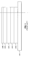
- FIG. 1 illustrates a typical thin film stack for conventional magnetic recording media.
- non-magnetic substrate 101 which is typically aluminum or glass.
- Seed layer 102 typically forces the shape and orientation of the grain structure of higher layers, and is commonly comprised of NiP or NiAl.
- a non-magnetic underlayer 104 which often includes one to three discrete layers, is deposited, where the underlayer is typically a chromium-based alloy, such as CrMo, or CrTi.
- Interlayer 105 which includes one or two separate layers, is formed above underlayer 104, where interlayer 105 is cobalt-based and slightly magnetic.
- Overlayer 106 which is magnetic and may include two or three separate layers, is deposited on top of interlayer 105, and carbon lubricant layer 108 is formed over overlayer 106.
- the amount of data that can be stored per unit area on a magnetic recording medium is inversely proportional to the size of the grain of the overlayer.
- Grain boundary segregation of minor addition elements also contributes to increased data storage potential.
- Grain size and uniform grain boundary segregation of the overlayer can be influenced by the properties of an earlier deposited thin film of the stack and particularly by the properties of an underlayer.
- underlayer alloys One technique for promoting desirable microstructures in a magnetic alloy thin film layer is through the use of underlayer alloys. Chromium containing underlayers exhibit a tendency to promote epitaxial growth of magnetic crystalline planes in cobalt alloy magnetic films. Chromium underlayers additionally promote fine grain structure, which reduces media noise in the magnetic film application. Underlayer alloys can be generally described as Cr-X-Y alloy systems.
- the X element represents large atom elements such as Mo, Ta or W that expand a chromium alloy lattice.
- the Y element represents smaller atom elements such as boron, B, which tends to segregate to grain boundaries and serves or acts as a grain growth inhibitor.
- Sputter targets made from consolidated materials of powder blends containing graphite powder in elemental form are prone to particle generation occurring through spitting during the sputtering process.
- the use of graphite powder in preparing sputter target material also yields unfavorable carbon distributions throughout the target. Accordingly, conventional techniques for producing carbon containing chromium alloys detract from their use as sputter target material and temper any beneficial epitaxial growth properties of such alloys that can be achieved in cobalt alloy magnetic recording layers.
- the embodiments of the present invention intend to solve the foregoing problems by providing a powder metallurgy method for manufacturing sputter target material for sputtering an underlayer of a magnetic recording medium, where the sputter target is comprised of a carbon containing chromium alloy composition which effectuates favourable epitaxial growth for optimal match with a cobalt alloy thin film layer.
- the present invention provides a sputter target material.
- the sputter target material has an alloy system comprising Cr-C, Cr-M-C or Cr-M 1 -M 2 -C, wherein C comprises at least 0.5 and as much as 20 atomic percent; M comprises at least 0.5 and as much as 20 atomic percent and is an element selected from the group consisting of Ti, V, Y, Zr, Nb, Mo, Hf, Ta, and W; M 1 comprises at least 0.5 and as much as 20 atomic percent and is an element selected from the group consisting of Ti, V, Zr, Nb, Mo, Hf, Ta, and W, and M 2 comprises at least 0.5 and as much as 10 atomic percent and is an element selected from the group consisting of Li, Mg, A1, Sc, Mn, Y, and Te.
- the invention provides a magnetic recording medium.
- the magnetic recording medium comprises a substrate and at least an underlayer.
- the underlayer has an alloy system comprising Cr-C, Cr-M-C, and Cr-M 1 -M 2 -C, wherein C comprises at least 0.5 and as much as 20 atomic percent; M comprises at least 0.5 and as much as 20 atomic percent and is an element selected from the group consisting of Ti, V, Y, Zr, Nb, Mo, Hf, Ta, and W; M 1 comprises at least 0.5 and as much as 20 atomic percent and is an element selected from the group consisting of Ti, V, Zr, Nb, Mo, Hf, Ta, and W, and M 2 comprises at least 0.5 and as much as 10 atomic percent and is an element selected from the group consisting of Li, Mg, Al, Sc, Mn, Y, and Te.
- a method of manufacturing a sputter target material comprises: (a) selecting powder materials of elements, or a combination of elements thereof, for an alloy system comprising Cr-C, Cr-M-C or Cr-M 1 -M 2 -C, wherein C comprises at least 0.5 and as much as 20 atomic percent; M comprises at least 0.5 and as much as 20 atomic percent and is an element selected from the group consisting of Ti, V, Y, Zr, Nb, Mo, Hf, Ta, and W; M 1 comprises at least 0.5 and as much as 20 atomic percent and is an element selected from the group consisting ofTi, V, Zr, Nb, Mo, Hf, Ta, and W, and M 2 comprises at least 0.5 and as much as 10 atomic percent and is an element selected from the group consisting of Li, Mg, Al, Sc, Mn, Y, and Te, and wherein the powder materials are selected to have at least a purity level, mesh size and particle morph
- Powder materials comprising a combination of elements can include a chromium alloy such as chromium carbide. Powder materials comprising a combination of elements also can include a carbide or carbon containing master alloy. Exemplary carbides or carbon containing master alloys can be Ti-C, V-C, Y-C, Zr-C, Nb-C, Mo-C, Hf-C, Ta-C, W-C, Li-C, Mg-C, Al-C, Sc-C, Mn-C, Y-C, and Te-C.
- the present invention allows for increased data storage of a magnetic recording medium by manufacturing carbon containing chromium alloy sputter target material from raw materials of individual elements, carbides or from master alloys containing carbon in order to achieve optimal epitaxial growth in a sputtered underlayer and epitaxial match with a sputtered magnetic overlayer thin film.
- sputter target materials having alloy systems represented by the formula Cr-C, Cr-M-C or Cr-M 1 -M 2 -C confers versatility to the production of a wide range of carbon containing alloy systems.
- Manufacture of the sputter target materials of the invention employs powder formulations of individual elements, carbides or carbon containing master alloys containing elements belonging to groups II-A through VIIA and groups I-B through IV-B of the periodic table.
- the manufacturing method of the invention provides an efficient means for producing carbon containing alloys in which the distribution of carbon containing particles can be optimized through the selection of favorable stoichiometry of individual elements, carbides or master alloy additives as well as the particle size distribution of those additives.
- Another beneficial attribute of employing elemental powder materials, carbides or master alloys rather than pure metal, graphite or both reduces particle generation during sputter as a result of erosion and spitting.
- the invention provides a sputter target material.
- the sputter target material includes an alloy system comprising Cr-C, Cr-M-C or Cr-M 1 -M 2 -C, wherein C comprises at least 0.5 and as much as 20 atomic percent; M comprises at least 0.5 and as much as 20 atomic percent and is an element selected from the group consisting of Ti, V, Y, Zr, Nb, Mo, Hf, Ta, and W; M 1 comprises at least 0.5 and as much as 20 atomic percent and is an element selected from the group consisting of Ti, V, Zr, Nb, Mo, Hf, Ta, and W, and M 2 comprises at least 0.5 and as much as 10 atomic percent and is an element selected from the group consisting of Li, Mg, Al, Sc, Mn, Y, and Te.
- the sputter target material can be manufactured by densifying a powder blend formulation of the alloy system as described further below. Densification processes can include, for example, procedures such as hot isostatic pressing (HIP); other high pressure, high temperature processes; cold powder press and sinter, and other pressureless methods as well as other procedures well known to those skilled in the powder metallurgy art.
- HIP hot isostatic pressing
- other high pressure, high temperature processes cold powder press and sinter, and other pressureless methods as well as other procedures well known to those skilled in the powder metallurgy art.
- Sputter target material of the invention ca n include, for example, any combination of atomic percentages of carbon, C, and of elements of groups II-A through VII-A and groups I-B through IV-B of the periodic table as set forth above.
- Sputter target material can have a carbon composition ranging from at least 0.5 and as much as 20 atomic percent.
- Other embodiments include a carbon composition within a sputter target material ranging from at least 1.0 and as much as 10 atomic percent. Further embodiments include carbon ranging from at least 1.5 and as much as 8 atomic percent.
- Exemplary embodiments of sputter target materials having the alloy system Cr-M-C, where carbon consists of 2-6 atomic percent include Cr-20M-6C, Cr-20M-2C, Cr-6M-4C, Cr-20M-4C and Cr-6M-2C, where numbers correspond to atomic percent of the referenced element within the alloy. All atomic percentages within the above exemplary ranges also can be employed in a sputter target material of the invention. Those skilled in the art will understand that selection and production of a sputter target material having a particular atomic percent of carbon within the above ranges can be performed using the methods of the invention described herein.
- Sputter target materials of the invention also will include a composition of elements of groups II-A through VII-A and groups I-B through IV-B.
- these elements include M, which can be selected from the elements Ti, V, Y, Zr, Nb, Mo, Hf, Ta, and W, or M 1 , which can be selected from the elements Ti, V, Zr, Nb, Mo, Hf, Ta, and W, and M 2 , which can be selected from the elements Li, Mg, Al, Sc, Mn, Y, and Te.
- the atomic percent can be at least 10 and as much as 50 atomic percent.
- exemplary embodiments of sputter target materials having the alloy system Cr-C, Cr-M-C or Cr-M 1 -M 2 -C include Cr-4C, Cr-15W-SC, Cr-20Mo-2Ti-2C and Cr-20Mo-2Ta-2C.
- a sputter target material can have a composition of M ranging from at least 0.5 and as much as 20 atomic percent.
- Other embodiments include a composition of M within a sputter target material ranging from at least 1.0 and as much as 10 atomic percent. Further embodiments include M ranging from at least 1.5 and as much as 8 atomic percent.
- Exemplary embodiments of sputter target materials where M is Mo the atomic percent of Mo consists of 6-20 atomic percent and include Cr-20M-6C, Cr-20M-2C, Cr-6M-4C, Cr-20M-4C and Cr-6M-2C, where numbers correspond to atomic percent of the referenced element within the alloy.
- sputter target materials having all atomic percentages of M within these exemplary ranges also can produced using the methods of the invention.
- Sputter target materials for the alloy system Cr-M 1 -M 2 -C can have a composition of M 1 ranging from at least 0.5 and as much as 20 atomic percent.
- Other embodiments include a composition of M 1 within a sputter target material ranging from at least 1.0 and as much as 10 atomic percent. Additional embodiments include M 1 ranging from at least 1.5 and as much as 8 atomic percent.
- the alloy system can have a composition of M 2 ranging from at least 0.5 and as much as 10 atomic percent.
- Other embodiments include a composition of M 2 ranging from at least 1.0 and as much as 4.0 atomic percent. Further embodiments include M 2 ranging from at least 1.5 and as much as 3.5 atomic percent.
- Exemplary embodiments of sputter target materials where either M 1 or M2 is Mo the atomic percent of Mo includes 6-20 atomic percent.
- sputter target materials having all atomic percentages of M 1 or M 2 as well as all possible combinations and permutations of these percentages within the above exemplary ranges can be produced using the methods of the invention.
- Sputter target materials comprising an alloy system of the invention will have a chromium composition comprising the balance of the alloy to reach 100 atomic percent.
- the chromium composition will correspond to 100 atomic percent less the atomic percentage of C contained in the alloy system.
- Cr can range from 80 to 99.5 atomic percent in a sputter target material comprising a Cr-C alloy system.
- Sputter target material having an alloy system Cr-M-C will have a chromium composition corresponding to 100 atomic percent less the atomic percentages of the sum of M and C contained in the alloy system.
- Cr can range from 60 to 99 atomic percent in a sputter target material.
- an alloy system Cr-M-C consisting of Cr-6Mo-2C will have a chromium composition of 92 atomic percent.
- sputter target material having an alloy system Cr-M 1 -M 2 -C will have a chromium composition corresponding to 100 atomic percent less the atomic percentages of the sum of M 1 , M 2 and C contained in the alloy system.
- Cr can range from 50 to 98.5 atomic percent in a sputter target material having a Cr-M 1 -M 2 -C alloy system of the invention.
- a sputter target material can be produced having all possible permutations and combinations of elements Cr, M, M 1 , M 2 and C for any of the allow systems Cr-C, Cr-M-C or Cr-M 1 -M 2 -C given the teachings and guidance provided herein.
- the choice of an alloy system, the atomic percentage of each element and which elements to use for M, M 1 or M 2 can be selected, for example, on the intended use of the sputter target material. All of the alloy systems described herein promote efficient epitaxial growth and matching for magnetic recording media.
- alloy system, elemental composition and/or atomic percentages of a selected alloy system of the invention can be varied to optimize epitaxial matching for use with different magnetic recording media, for example. Making and testing differing compositions of an alloy system the invention for optimization is well known to those skilled in the art.
- the invention also provides a sputter target formulation.
- the sputter target formulation includes powder blend materials of elements, or a combination of elements thereof, for an alloy system comprising Cr-C, Cr-M-C or Cr-M 1 -M 2 -C, wherein C comprises at least 0.5 and as much as 20 atomic percent; M comprises at least 0.5 and as much as 20 atomic percent and is an element selected from the group consisting of Ti, V, Y, Zr, Nb, Mo, Hf, Ta, and W; M 1 comprises at least 0.5 and as much as 20 atomic percent and is an element selected from the group consisting of Ti, V, Zr, Nb, Mo, Hf, Ta, and W, and M 2 comprises at least 0.5 and as much as 10 atomic percent and is an element selected from the group consisting of Li, Mg, Al, Sc, Mn, Y, and Te, and wherein said powder materials are selected to have at least a purity level, mesh size and particle morphology effective for a sp
- the sputter target formulations of the invention consist of powder blends of raw materials of elements used for the production of a sputter target material of the invention.
- the raw materials of elements are selected as described below and combined into an unconsolidated blend prior to consolidation by densification. Therefore, the formulations comprise unconsolidated powder blend materials of elements and atomic percentages corresponding to any of the alloy systems described previously for a sputter target material of the invention.
- the formulations also can include unconsolidated powder blend materials where one or more of such materials corresponds to a combination of elements of an alloy systems of the invention.
- two or more powder materials corresponding to combinations of elements also can be included in a sputter target formulation of the invention.
- Combinations of elements can include, for example, stoichiometrically favorable aggregates of two or more elements selected from Cr, M, M 1 , M 2 or C.
- Constituents of the sputter target formulations corresponding to powdered materials of elements include, for example, Cr, C, M where M is selected from Ti, V, Y, Zr, Nb, Mo, Hf, Ta, and W, M 1 where M 1 is selected from Ti, V, Zr, Nb, Mo, Hf, Ta, and W, and M 2 where M 2 is selected from Li, Mg, Al, Sc, Mn, Y, and Te.
- the constituents of a formulation can be in the form of raw materials corresponding to an individual element. Alternatively, constituents can be present in the form of combinations of the above elements.
- a combination of elements can be any binary or higher order compound and includes, for example, an alloy, a master alloy or a carbide.
- powder materials of a combination of elements include a chromium alloy or a carbon containing master alloy.
- Exemplary carbides include Cr-C, Ti-C, V-C, Y-C, Zr-C, Nb-C, Mo-C, Hf-C, Ta-C, W-C, Li-C, Mg-C, Al-C, Sc-C, Mn-C, Y-C or Te-C, and having a stoichiometry well known in the art.
- Sputter target formulations can be blended to contain a wide variety of constituent powder materials of elements or combinations thereof. For example, powder materials for each individual element are selected and combined into an unconsolidated formulation in specified atomic percentages that correspond to one or more of the alloy systems described previously.
- a sputter target formulation can be blended from one or more individual elements and from one or more materials corresponding to a combination of elements such as a carbide, an alloy or a master alloy. The alloy or master alloy can additionally contain carbon.
- a sputter target formulation also can be blended from two or more materials corresponding to a combination of elements that specify an alloy system of the invention.
- the powder materials of elements corresponding to constituents of a sputter target formulation can vary so long as the final formulation contains constituent elements and atomic percentages that specify an alloy system of the invention.
- the processes of selection and combining into a formulation can be performed as described below or according to methods well known in the material sciences.
- the resultant sputter target formulation can be densified to produce a sputter target.
- the invention provides a magnetic recording medium.
- the magnetic recording medium comprises a substrate and at least an underlayer.
- the underlayer of the magnetic recording medium includes an alloy system comprising Cr-C, Cr-M-C, and Cr-M 1- M 2 -C, wherein C comprises at least 0.5 and as much as 20 atomic percent; M comprises at least 0.5 and as much as 20 atomic percent and is an element selected from the group consisting of Ti, V, Y, Zr, Nb, Mo, Hf, Ta, and W; M 1 comprises at least 0.5 and as much as 20 atomic percent and is an element selected from the group consisting of Ti, V, Zr, Nb, Mo, Hf, Ta, and W, and M 2 comprises at least 0.5 and as much as 10 atomic percent and is an element selected from the group consisting of Li, Mg, Al, Sc, Mn, Y, and Te.
- a sputter target material produced from the powder metallurgy methods of the invention can be used to sputter onto a substrate to manufacture a thin film layer comprised of the alloy system for the chosen sputter target.
- An exemplary thin film layer that can be produced using the sputter targets of the invention is an underlayer of a magnetic recording medium.
- Underlayers comprised of an alloy system of the invention represented by the formula Cr-C, Cr-M-C or Cr-M 1 -M 2 -C promote favorable epitaxial growth of magnetic crystalline planes in cobalt alloy overlayer thin films. Therefore, sputter targets can be produced from sputter target material of the invention and used to sputter a variety of underlayer thin films for the production of different magnetic recording media useful in a wide range of applications.
- the magnetic recording medium includes a substrate, and at least one underlayer formed over the substrate, where the underlayer includes an alloy system comprising Cr-C, Cr-M-C, and Cr-M 1 -M 2 -C, wherein C comprises at least 0.5 and as much as 20 atomic percent; M comprises at least 0.5 and as much as 20 atomic percent and is an element selected from the group consisting of Ti, V, Y, Zr, Nb, Mo, Hf, Ta, and W; M 1 comprises at least 0.5 and as much as 20 atomic percent and is an element selected from the group consisting of Ti, V, Zr, Nb, Mo, Hf, Ta, and W, and M 2 comprises at least 0.5 and as much as 10 atomic percent and is an element selected from the group consisting of Li, Mg, Al, Sc, Mn, Y, and Te.
- C comprises at least 0.5 and as much as 20 atomic percent
- M comprises at least 0.5 and as much as 20 atomic percent and is an element selected from the group consisting of Ti,
- the magnetic recording medium also can include, for example, at least one interlayer formed over the underlayer.
- An exemplary interlayer can consist of a Co-based alloy.
- the magnetic recording medium can additionally include, for example, at least one overlayer formed over the interlayer.
- the overlayer similarly can consist of a Co-based alloy.
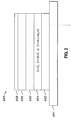
- an exemplary thin film stack of a magnetic recording medium 400 includes substrate 401, which is generally aluminum or glass.
- Seed layer 402 can be formed over substrate 401, where seed layer 402 molds the shape and orientation of the grain structure of subsequently deposited thin film layers.
- seed layer 402 can consist of NiP or NiAl. In an alternate arrangement of the present invention, seed layer 402 can be omitted.
- Underlayer 404 is formed over seed layer 402, or over substrate 401 if seed layer 402 is omitted. Although underlayer 404 is depicted as one layer, in alternate aspects of the present invention underlayer 404 can consist of from one to three or more layers. Underlayer 404 is comprised of an alloy system of the invention having the formula Cr-C, Cr-M-C or Cr-M 1 -M 2 -C, where C comprises at least 0.5 and as much as 20 atomic percent; M comprises at least 0.5 and as much as 20 atomic percent and is an element selected from the group consisting of Ti, V, Y, Zr, Nb, Mo, Hf, Ta, and W; M 1 comprises at least 0.5 and as much as 20 atomic percent and is an element selected from the group consisting of Ti, V, Zr, Nb, Mo, Hf, Ta, and W; M 2 comprises at least 0.5 and as much as 10 atomic percent and is an element selected from the group consisting of Li, Mg, Al, Sc, Mn, Y, and Te
- Interlayer 405 can be formed over underlayer 404. Interlayer 405 is illustrated as one layer, however in an additional arrangement, interlayer 405 can consist of from one to three or more layers. Interlayer 405 can be comprised of a cobalt-based alloy and also can further include additional elements or compounds such as an oxide which facilitates favorable grain structure. Interlayer 406 can be slightly magnetic.
- Overlayer 406 can be formed over interlayer 405.
- overlayer 406 is shown as one layer.
- overlayer 405 can consist of from one to three or more layers.
- Overlayer 406 similarly can be comprised of a cobalt-based alloy and also can include additional elements or compounds such as an oxide which facilitate favorable grain structure.
- Carbon lubricant layer 408 can be formed over overlayer 406, where the lubricant layer includes C or a carbon-based alloy. Carbon lubricant layer 408 protects overlayer 406 from damage caused by physical contact between a read-write head (not depicted) and overlayer 408 itself. In an alternate aspect of the present invention, carbon lubricant layer 408 can be omitted.
- the invention provides a method of manufacturing a sputter target material having alloy systems represented by the formula Cr-C, Cr-M-C or Cr-M 1 -M 2 -C.
- powder materials of constituent elements, or combinations of constituent elements, corresponding to these alloy systems can be combined to produce unconsolidated formulations where C comprises at least 0.5 and as much as 20 atomic percent; M comprises at least 0.5 and as much as 20 atomic percent and is an element selected from the group consisting of Ti, V, Y, Zr, Nb, Mo, Hf, Ta, and W; M 1 comprises at least 0.5 and as much as 20 atomic percent and is an element selected from the group consisting of Ti, V, Zr, Nb, Mo, Hf, Ta, and W, and M 2 comprises at least 0.5 and as much as 10 atomic percent and is an element selected from the group consisting of Li, Mg, Al, Sc, Mn, Y, and Te.
- the powder materials of elements, or combinations thereof, are selected to have at least a purity level, mesh size and particle morphology effective for a sputter target material.
- the sputter target formulation can be consolidated by, for example, densification to produce a sputter target material, which can be subsequently processed into a sputter target.
- the method of manufacturing a sputter target material of the invention includes selection of powder materials of elements, or combinations of elements thereof, having desired physical and/or chemical properties.
- One advantage of the method of the invention is that stoichiometrically favorable aggregates of constituent elements can be selected and employed to manufacture all combinations of elements and atomic percentages of the alloy systems of the invention represented by the formula Cr-C, Cr-M-C or Cr-M 1 -M 2 -C.
- powder materials are selected for a desired alloy system.
- Cr and C are selected for a Cr-C alloy system.
- Powder material of elements Cr, C and M are selected for a Cr-M-C alloy system where M corresponds to any one of Ti, V, Y, Zr, Nb, Mo, Hf, Ta, and W.
- Cr, C, M 1 and M 2 are selected for a Cr-M 1 -M 2 -C alloy system where M 1 corresponds to any one of Ti, V, Zr, Nb, Mo, Hf, Ta or W and M 2 corresponds to any one of Li, Mg, Al, Sc, Mn, Y, and Te.
- Powder material of individual elements can be selected or combinations of elements can be selected that correspond to two or more elements of the desired alloy system.
- the carbides Mo-C and Cr-C can be selected in stoichiometrically favorable combinations as powder materials for manufacturing the alloy system Cr-M-C where M is Mo. Selection of powder materials of elements having desirable or predetermined physical and/or chemical properties is well known to those skilled in the art of material science.
- Selection of powder materials of elements having desired physical and/or chemical properties also includes selection of a powder material having a purity level effective for a sputter target material.
- An effective purity level will be chosen based on the intended application of the sputter target.
- Certain thin film applications require high purity levels to be effective as a thin film in a magnetic recording medium.
- High purity levels include powders of raw materials of elements, or combinations of elements such as the carbides or carbon containing alloys described previously, having a purity level of at least about 99.94 %.
- An example of a sputtered thin film underlayer having benefited by a high purity level is Cr-4C where the purity levels of the powder materials of elements correspond to 99.98 %Cr and 99.50 % Cr 3 C 2 .
- Other thin film applications can use lower purity levels of powder materials including, for example, purity levels of at least about 99.90% and as much as 99.93%.
- Still other sputtered thin film underlayer application can have lower purity levels of powder materials while still being effective and include, for example, purity levels of at least about 99.85 or lower % and as much as 99.89%.
- Specific examples of the underlayer applications requiring the latter two ranges of purity levels include Cr-15Mo-4C and Cr-20Mo-6C, respectively, where the purity levels of the powder materials of elements correspond to 99.98 % Cr, 99.90 % Mo and 99.5 % Mo 2 C.
- Selection of powder materials of elements for an alloy system of the invention can additionally include selection of a mesh size effective for a sputter target material.
- An effective mesh size will be chosen based on, for example, the amount of powder in the formulation mixture, which corresponds to the atomic percentage of the alloy system element within the formulation.
- An effective mesh size also can be chosen based on, or including, other physical and/or chemical properties such as the atomic size of the element or elements of the end product alloy system.
- Mesh size also can be chosen based on other factors and include, for example, consideration of atomic percentages with respect to the generation of homogeneous powder formulations. For example, smaller atomic percentages of a powder material require greater care in mixing with other powder materials of a formulation to produce a homogeneous or substantially homogeneous formulation. Finer mesh sizes for M, M 1 , M 2 and/or C can be selected for these constituents of an alloy system of the invention to achieve a higher uniformity and/or more optimal distribution throughout a sputter target material. Mesh size can be adjusted to match a particular mixing procedure by selecting a different element within a like group of elements for the alloy systems of the invention in order to achieve homogeneity of the powder formulation.
- Another factor includes the activation of phase changes beneficial to the alloy system.
- smaller mesh sizes such as those produced by carbon, can result in desirable activation of phase changes and therefore selected as an effective mesh size for a particular alloy system of the invention.
- Exemplary mesh sizes for powder materials of elements for the alloy system Cr-M-C, where M corresponds to Mo are 100 mesh for Cr, 325 mesh for Mo and 325 mesh for Carbide.
- Selection of powder materials of elements for an alloy system of the invention can further include selection of a particle morphology effective for a sputter target material.
- the particle shape of powdered elements, carbides or carbon containing master alloys effective for a sputter target can be chosen based on the desired densification process to be used in producing a sputter target.
- particle size of powder materials can be on the coarse mesh size where a hot isostatic pressing (HIP) method will be employed for densification.
- Coarser mesh sizes include, for example, 100 mesh.
- pressureless densification methods are to be used, selection of finer particle sizes are beneficial for complete sintering and achievement of up to 100% density for a alloy system of the invention.
- Lower pressure and temperature methods of densification include, for example, cold powder press and sinter.
- Exemplary particle sizes applicable for these methods of densification include, for example, 325 mesh.
- the above powder materials of elements can be produced by any of various chemical and physical methods well known in the art of material science.
- the above powder materials of elements, including combinations thereof such as carbides or carbon containing alloys also can be manufactured by any of various processes well known in the art of material sciences.
- a particularly useful manufacturing process includes atomization methods which can produce powder materials exhibiting beneficial characteristics such as uniform chemical homogeneity and spheroidal particle shape for improved densification when high pressure, high temperature processes are employed.
- Another alternative for making carbon containing chromium alloys is to use a pre-alloyed powder of chromium and carbon.
- This raw material can be prepared, for example, by melting and atomizing a Cr-C master alloy.
- 99.98 % Cr melt stock was melted by vacuum induction along with 99.9 % graphite flake.
- the desired composition for the pre-alloyed material was the combination of elements Cr-C where C was present at 14 atomic percent, or Cr-14C.
- the molten alloy was then gas atomized with a high pressure argon jet into fine droplets which subsequently solidified into spherical particles.
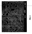
- the typical microstructure of the as-solidified powder is shown in Figure 3, which is a back-scattered image mode of a scanning electron micrograph (SEM). This micrograph reveals the microstructure through a particle section of the powder.
- SEM scanning electron micrograph
- the microstructure of the Cr-14C combination of elements consists of uniformly distributed 1-2 ⁇ m carbide particles (arrows) within a supersaturated chromium matrix.
- the chemical composition for this powder is listed in the following table: Ca ppm Fe ppm Mn ppm Ni ppm Si ppm V ppm O ppm N ppm S ppm C* at. % 64 186 7 7 81 46 32 9 87 13.82
- Powder materials of elements, or combinations thereof, that are constituents of an alloy system of the invention are combined into a sputter target formulation following selection of powder elements, or combinations thereof, having effective purity levels, mesh size and particle morphology.
- the powders are combined in selected amounts to achieve atomic percentages of an alloy system comprising Cr-C, Cr-M-C or Cr-M 1 -M 2 -C, where C comprises at least 0.5 and as much as 20 atomic percent; M comprises at least 0.5 and as much as 20 atomic percent and is an element selected from the group consisting of Ti, V, Y, Zr, Nb, Mo, Hf, Ta, and W; M 1 comprises at least 0.5 and as much as 20 atomic percent and is an element selected from the group consisting of Ti, V, Zr, Nb, Mo, Hf, Ta, and W, and M 2 comprises at least 0.5 and as much as 10 atomic percent and is an element selected from the group consisting of Li, Mg, Al, Sc, Mn, Y, and Te.
- Combining powder materials of elements, or combinations thereof includes mixing or blending the constituent powder materials to create a homogeneous or substantially homogenous powder formulation.
- the alloy formulations also can be generated using any of various chemical and physical methods well known in the art of material science including, for example, manufactured by atomization methods to achieve favorable homogeneity and morphology characteristics of the alloy formulation. Other methods well known to those skilled in the art of material science also can be employed to combine powder materials and/or to achieve homogeneous mixtures.
- a powder formulation is produced containing the elements and atomic percentages of the selected alloy system.
- This powder formulation can be stored for later use following procedures well known in the art of material science or it can be immediately used for the production of a sputter target material comprised of the selected alloy system.
- Sputter target material can be manufactured by densification methods in which a mass of powder is formed into a shape or "can,” then consolidated to form inter-particle metallurgical bonds.
- densification methods in which a mass of powder is formed into a shape or "can,” then consolidated to form inter-particle metallurgical bonds.
- elemental materials are mixed to produce a homogeneous blend, the powders are encapsulated in a metal container, and the container is out-gassed to avoid contamination of the materials by any residual gas.
- a hot isostatic pressing occurs on the container, in which heat and isostatic pressure are applied on the vessel to consolidate the powder, turning loose powder into a densified matter known as a "HIP'ed can.”
- the HIP'ed can then can be sliced to create multiple sputter target blanks, and the target blanks can be machined into an appropriate shape, which may be round, rectangular, or polygonal. Once shaping is complete, the sputter targets can be laid flat and polished with a grinder or abraded.
- Figures 4 illustrates a typical microstructure of a sputter target material with an alloy system having the formula Cr-C.
- Figure 5 illustrates a typical microstructure of a sputter target material with an alloy system having the formula Cr-M-C where M is Mo.
- C was introduced into a sputter target formulation using Cr or Mo carbides, respectively.
- Figure 4 illustrates a scanning electron micrograph (SEM) showing the distribution of the carbide phase in a Cr-C alloy manufactured by consolidation of Cr and Cr 2 C powder materials.
- Figure 5 illustrates a SEM showing the distribution of the carbide phase in a Cr-M-C alloy, where M consists of Mo, manufactured by consolidation of Cr, Mo and MO 2 C powder materials.
Landscapes
- Chemical & Material Sciences (AREA)
- Engineering & Computer Science (AREA)
- Organic Chemistry (AREA)
- Materials Engineering (AREA)
- Mechanical Engineering (AREA)
- Metallurgy (AREA)
- Chemical Kinetics & Catalysis (AREA)
- Power Engineering (AREA)
- Manufacturing & Machinery (AREA)
- Physics & Mathematics (AREA)
- Spectroscopy & Molecular Physics (AREA)
- Physical Vapour Deposition (AREA)
- Manufacturing Of Magnetic Record Carriers (AREA)
- Powder Metallurgy (AREA)
- Magnetic Record Carriers (AREA)
Priority Applications (1)
| Application Number | Priority Date | Filing Date | Title |
|---|---|---|---|
| EP07001965A EP1780300A3 (fr) | 2004-11-24 | 2005-08-25 | Composition d'une alliage pour une cible de pulverisation comprenant du carbone |
Applications Claiming Priority (1)
| Application Number | Priority Date | Filing Date | Title |
|---|---|---|---|
| US10/995,112 US20060110626A1 (en) | 2004-11-24 | 2004-11-24 | Carbon containing sputter target alloy compositions |
Related Child Applications (1)
| Application Number | Title | Priority Date | Filing Date |
|---|---|---|---|
| EP07001965A Division EP1780300A3 (fr) | 2004-11-24 | 2005-08-25 | Composition d'une alliage pour une cible de pulverisation comprenant du carbone |
Publications (2)
| Publication Number | Publication Date |
|---|---|
| EP1662018A2 true EP1662018A2 (fr) | 2006-05-31 |
| EP1662018A3 EP1662018A3 (fr) | 2006-11-08 |
Family
ID=35809747
Family Applications (2)
| Application Number | Title | Priority Date | Filing Date |
|---|---|---|---|
| EP07001965A Withdrawn EP1780300A3 (fr) | 2004-11-24 | 2005-08-25 | Composition d'une alliage pour une cible de pulverisation comprenant du carbone |
| EP05255241A Withdrawn EP1662018A3 (fr) | 2004-11-24 | 2005-08-25 | Composition d'une alliage pour une cible de pulverisation comprenant du carbone |
Family Applications Before (1)
| Application Number | Title | Priority Date | Filing Date |
|---|---|---|---|
| EP07001965A Withdrawn EP1780300A3 (fr) | 2004-11-24 | 2005-08-25 | Composition d'une alliage pour une cible de pulverisation comprenant du carbone |
Country Status (8)
| Country | Link |
|---|---|
| US (1) | US20060110626A1 (fr) |
| EP (2) | EP1780300A3 (fr) |
| JP (1) | JP2006144117A (fr) |
| KR (2) | KR100731832B1 (fr) |
| CN (1) | CN1807679A (fr) |
| CZ (1) | CZ2005539A3 (fr) |
| SG (2) | SG122875A1 (fr) |
| TW (1) | TWI288784B (fr) |
Cited By (1)
| Publication number | Priority date | Publication date | Assignee | Title |
|---|---|---|---|---|
| SG140517A1 (en) * | 2006-09-01 | 2008-03-28 | Heraeus Inc | Magnetic media and sputter targets with compositions of high anisotropy alloys and oxide compounds |
Families Citing this family (11)
| Publication number | Priority date | Publication date | Assignee | Title |
|---|---|---|---|---|
| JP5912559B2 (ja) * | 2011-03-30 | 2016-04-27 | 田中貴金属工業株式会社 | FePt−C系スパッタリングターゲットの製造方法 |
| TWI515316B (zh) | 2012-01-13 | 2016-01-01 | 田中貴金屬工業股份有限公司 | FePt sputtering target and its manufacturing method |
| JP6210503B2 (ja) * | 2012-08-13 | 2017-10-11 | 山陽特殊製鋼株式会社 | 磁気記録用軟磁性用合金およびスパッタリングターゲット材 |
| CN115094390A (zh) * | 2014-09-30 | 2022-09-23 | 捷客斯金属株式会社 | 溅射靶用母合金和溅射靶的制造方法 |
| US9771634B2 (en) | 2014-11-05 | 2017-09-26 | Companhia Brasileira De Metalurgia E Mineração | Processes for producing low nitrogen essentially nitride-free chromium and chromium plus niobium-containing nickel-based alloys and the resulting chromium and nickel-based alloys |
| US10041146B2 (en) | 2014-11-05 | 2018-08-07 | Companhia Brasileira de Metalurgia e Mineraçäo | Processes for producing low nitrogen metallic chromium and chromium-containing alloys and the resulting products |
| CN105986138A (zh) * | 2016-06-24 | 2016-10-05 | 贵研铂业股份有限公司 | 一种制备超高纯镍铂合金靶材的方法 |
| DE102018201771A1 (de) * | 2018-02-06 | 2019-08-08 | Fraunhofer-Gesellschaft zur Förderung der angewandten Forschung e.V. | Wässrige Suspension enthaltend Metallcarbid-Partikel |
| CN109735804B (zh) * | 2019-01-30 | 2020-01-03 | 湘潭大学 | 一种金属碳化合物涂层及其制备方法 |
| CN114959572A (zh) * | 2022-05-23 | 2022-08-30 | 湘潭大学 | 一种钨掺杂碳化钽铪薄膜材料及其制备方法 |
| CN115976481B (zh) * | 2022-12-23 | 2024-09-17 | 南京航空航天大学 | 一种靶材、金属钽表面复合梯度陶瓷涂层的制法及其所得涂层 |
Family Cites Families (45)
| Publication number | Priority date | Publication date | Assignee | Title |
|---|---|---|---|---|
| US3147112A (en) * | 1961-01-19 | 1964-09-01 | Du Pont | Ferromagnetic mn-ga alloy and method of production |
| US3554737A (en) * | 1968-05-21 | 1971-01-12 | Battelle Development Corp | Cast refractory alloy |
| US3846084A (en) * | 1973-08-15 | 1974-11-05 | Union Carbide Corp | Chromium-chromium carbide powder and article made therefrom |
| US4221610A (en) * | 1978-02-24 | 1980-09-09 | The United States Of America As Represented By The United States Department Of Energy | Method for homogenizing alloys susceptible to the formation of carbide stringers and alloys prepared thereby |
| JPS59185022A (ja) * | 1983-04-04 | 1984-10-20 | Fuji Photo Film Co Ltd | 磁気記録媒体 |
| CA2062154C (fr) * | 1991-05-14 | 1997-01-21 | David Alvoid Edmonson | Dopage de la couche de dessous d'un support d'enregistrement magnetique a couches minces |
| US5232566A (en) * | 1991-05-14 | 1993-08-03 | International Business Machines Corporation | Underlayer doping in thin film magnetic recording media |
| US5342571A (en) * | 1992-02-19 | 1994-08-30 | Tosoh Smd, Inc. | Method for producing sputtering target for deposition of titanium, aluminum and nitrogen coatings, sputtering target made thereby, and method of sputtering with said targets |
| JPH06349061A (ja) * | 1993-06-04 | 1994-12-22 | Hoya Corp | 磁気記録媒体の製造方法 |
| US5723198A (en) * | 1993-06-11 | 1998-03-03 | Hitachi, Ltd. | Multi-layered magnetic recording medium and magnetic recording system employing the same |
| JPH0850715A (ja) * | 1994-01-28 | 1996-02-20 | Komag Inc | 低ノイズ,高い保磁力および優れた方形度を有する磁気記録媒体および磁気記録媒体形成方法 |
| US5846648A (en) * | 1994-01-28 | 1998-12-08 | Komag, Inc. | Magnetic alloy having a structured nucleation layer and method for manufacturing same |
| US5650889A (en) * | 1994-02-07 | 1997-07-22 | Hitachi, Ltd. | Magnetic recording medium containing heavy rare gas atoms, and a magnetic transducing system using the medium |
| US7396501B2 (en) * | 1994-08-12 | 2008-07-08 | Diamicron, Inc. | Use of gradient layers and stress modifiers to fabricate composite constructs |
| JP3772357B2 (ja) * | 1995-02-21 | 2006-05-10 | 東ソー株式会社 | スパッタリングターゲット及びその製造方法 |
| US6821707B2 (en) * | 1996-03-11 | 2004-11-23 | Matsushita Electric Industrial Co., Ltd. | Optical information recording medium, producing method thereof and method of recording/erasing/reproducing information |
| TW390998B (en) * | 1996-05-20 | 2000-05-21 | Hitachi Ltd | Magnetic recording media and magnetic recording system using the same |
| WO1998006093A1 (fr) * | 1996-05-20 | 1998-02-12 | Hitachi, Ltd. | Support d'enregistrement magnetique et dispositif de memoire magnetique utilisant un tel support |
| JP3544293B2 (ja) * | 1997-07-31 | 2004-07-21 | 株式会社日鉱マテリアルズ | 磁性材用Mn合金材料、Mn合金スパッタリングタ−ゲット及び磁性薄膜 |
| US6387483B1 (en) * | 1997-12-18 | 2002-05-14 | Nec Corporation | Perpendicular magnetic recording medium and manufacturing process therefor |
| JP4491844B2 (ja) | 1998-07-24 | 2010-06-30 | 東ソー株式会社 | スパッタリングターゲット |
| US6432562B1 (en) | 1998-09-25 | 2002-08-13 | Seagate Technology Llc | Magnetic recording medium with a nialru seedlayer |
| US6699588B2 (en) * | 1999-07-22 | 2004-03-02 | Seagate Technology, Inc. | Medium with a NiNb sealing layer |
| US6475276B1 (en) * | 1999-10-15 | 2002-11-05 | Asm Microchemistry Oy | Production of elemental thin films using a boron-containing reducing agent |
| US6583958B1 (en) * | 1999-11-18 | 2003-06-24 | Hitachi, Ltd. | Magnetic recording medium and magnetic storage system using same |
| US6620531B1 (en) * | 1999-12-20 | 2003-09-16 | Seagate Technology Llc | Magnetic recording media with oxidized seedlayer for reduced grain size and reduced grain size distribution |
| FI20000099A0 (fi) * | 2000-01-18 | 2000-01-18 | Asm Microchemistry Ltd | Menetelmä metalliohutkalvojen kasvattamiseksi |
| US6514358B1 (en) * | 2000-04-05 | 2003-02-04 | Heraeus, Inc. | Stretching of magnetic materials to increase pass-through-flux (PTF) |
| US6740397B1 (en) * | 2000-05-24 | 2004-05-25 | Seagate Technology Llc | Subseedlayers for magnetic recording media |
| AT408665B (de) * | 2000-09-14 | 2002-02-25 | Boehler Edelstahl Gmbh & Co Kg | Nickelbasislegierung für die hochtemperaturtechnik |
| US7112549B2 (en) * | 2000-09-20 | 2006-09-26 | Sumitomo Metal Industries, Ltd. | Low thermal expansion ceramic and member for exposure system |
| JP2002100018A (ja) * | 2000-09-25 | 2002-04-05 | Fujitsu Ltd | 磁気記録媒体及びその製造方法並び磁気記憶装置 |
| GB0024031D0 (en) * | 2000-09-29 | 2000-11-15 | Rolls Royce Plc | A nickel base superalloy |
| JP4128735B2 (ja) * | 2000-10-26 | 2008-07-30 | 富士フイルム株式会社 | 磁気テープ |
| JP3607946B2 (ja) * | 2001-03-07 | 2005-01-05 | 独立行政法人物質・材料研究機構 | Cr基耐熱合金 |
| US6589602B2 (en) * | 2001-04-17 | 2003-07-08 | Toshiba Tungaloy Co., Ltd. | Highly adhesive surface-coated cemented carbide and method for producing the same |
| US6746782B2 (en) * | 2001-06-11 | 2004-06-08 | General Electric Company | Diffusion barrier coatings, and related articles and processes |
| JP3993786B2 (ja) * | 2001-06-29 | 2007-10-17 | 富士通株式会社 | 磁気記録媒体 |
| US20040112476A1 (en) * | 2001-07-09 | 2004-06-17 | Geoffrey Dearnaley | Life extension of chromium coatings and chromium alloys |
| US6567236B1 (en) * | 2001-11-09 | 2003-05-20 | International Business Machnes Corporation | Antiferromagnetically coupled thin films for magnetic recording |
| US20030228238A1 (en) * | 2002-06-07 | 2003-12-11 | Wenjun Zhang | High-PTF sputtering targets and method of manufacturing |
| US7141315B2 (en) * | 2002-07-31 | 2006-11-28 | Showa Denko K.K. | Magnetic recording medium, method of manufacturing the same, and magnetic recording and reproduction apparatus |
| AU2003291159A1 (en) * | 2002-12-09 | 2004-06-30 | Honeywell International Inc. | High purity nickel/vanadium sputtering components; and methods of making sputtering components |
| JP2004326889A (ja) * | 2003-04-23 | 2004-11-18 | Hitachi Global Storage Technologies Inc | 磁気記録媒体 |
| JP2004355716A (ja) * | 2003-05-29 | 2004-12-16 | Hitachi Global Storage Technologies Netherlands Bv | 磁気記録媒体 |
-
2004
- 2004-11-24 US US10/995,112 patent/US20060110626A1/en not_active Abandoned
-
2005
- 2005-08-25 EP EP07001965A patent/EP1780300A3/fr not_active Withdrawn
- 2005-08-25 EP EP05255241A patent/EP1662018A3/fr not_active Withdrawn
- 2005-08-26 CZ CZ20050539A patent/CZ2005539A3/cs unknown
- 2005-08-30 TW TW094129694A patent/TWI288784B/zh not_active IP Right Cessation
- 2005-09-26 SG SG200506160A patent/SG122875A1/en unknown
- 2005-09-26 SG SG200703116-4A patent/SG131953A1/en unknown
- 2005-09-28 KR KR1020050090556A patent/KR100731832B1/ko not_active Expired - Fee Related
- 2005-10-18 JP JP2005303259A patent/JP2006144117A/ja active Pending
- 2005-10-18 CN CNA2005101140679A patent/CN1807679A/zh active Pending
-
2007
- 2007-01-17 KR KR1020070005428A patent/KR100774608B1/ko not_active Expired - Fee Related
Cited By (1)
| Publication number | Priority date | Publication date | Assignee | Title |
|---|---|---|---|---|
| SG140517A1 (en) * | 2006-09-01 | 2008-03-28 | Heraeus Inc | Magnetic media and sputter targets with compositions of high anisotropy alloys and oxide compounds |
Also Published As
| Publication number | Publication date |
|---|---|
| KR100774608B1 (ko) | 2007-11-09 |
| KR20070012880A (ko) | 2007-01-29 |
| EP1780300A3 (fr) | 2008-03-05 |
| CZ2005539A3 (cs) | 2007-01-10 |
| US20060110626A1 (en) | 2006-05-25 |
| CN1807679A (zh) | 2006-07-26 |
| TW200619408A (en) | 2006-06-16 |
| KR100731832B1 (ko) | 2007-06-25 |
| EP1662018A3 (fr) | 2006-11-08 |
| TWI288784B (en) | 2007-10-21 |
| KR20060057999A (ko) | 2006-05-29 |
| JP2006144117A (ja) | 2006-06-08 |
| EP1780300A2 (fr) | 2007-05-02 |
| SG122875A1 (en) | 2006-06-29 |
| SG131953A1 (en) | 2007-05-28 |
Similar Documents
| Publication | Publication Date | Title |
|---|---|---|
| KR100774608B1 (ko) | 탄소함유 스퍼터 타겟 합금 조성물 | |
| US7229588B2 (en) | Mechanically alloyed precious metal magnetic sputtering targets fabricated using rapidly solidified alloy powders and elemental Pt metal | |
| EP1652960B1 (fr) | Cible de pulverisation et procede de production correspondant | |
| US6159625A (en) | Target of intermetallic compound with B2-ordered lattice structure, production method thereof and magnetic recording medium having B2-structured underlayer | |
| EP1942205A2 (fr) | Cibles de pulvérisation et procédés de fabrication de cibles de pulvérisation dotées de matériaux multiples | |
| US20090120237A1 (en) | Enhanced formulation of cobalt alloy matrix compositions | |
| EP0759480A1 (fr) | Alliage dur contenant du carbure de tungstène lamellaire, composition pour la préparation de carbure de tungstène lamellaire et procédé pour la préparation de l'alliage dur | |
| KR102869752B1 (ko) | 고엔트로피 초경소재 및 이의 제조방법 | |
| KR20230065436A (ko) | 비정질 및 나노 결정질을 포함하는 합금막의 제조방법 및 비정질 및 나노 결정질을 포함하는 합금막 | |
| JP3170412B2 (ja) | 金属薄膜型磁気記録媒体の非磁性下地膜形成用スパッタリングターゲット部材 | |
| US20070285839A1 (en) | Perpendicular magnetic recording medium and method of manufacturing the same | |
| JP7730622B2 (ja) | スパッタリングターゲット、グラニュラ膜および垂直磁気記録媒体 | |
| HK1086309A (en) | Carbon containing sputter target alloy compositions | |
| HK1098796A (en) | Carbon containing sputter target alloy compositions | |
| TWI512126B (zh) | A sputtering target and a method for producing the same, and a film produced by using the same | |
| KR20240139127A (ko) | 높은 파괴인성을 갖는 금속 박막 및 이의 제조방법 | |
| KR102892170B1 (ko) | 비정질 박막 및 결정질막을 포함하는 복층막을 포함하는, 다층 박막의 제조방법 및 이에 따라 제조된 다층 박막 | |
| WO2020031460A1 (fr) | Cible de pulvérisation, film magnétique et support d'enregistrement magnétique perpendiculaire | |
| JP2802850B2 (ja) | ターゲツト材およびその製造方法 | |
| JP2802851B2 (ja) | ターゲツト材およびその製造方法 | |
| JPH0641734A (ja) | ターゲツト部材およびその製造方法 | |
| HK1091235B (en) | Enhanced formulation of cobalt alloy matrix compositions | |
| JPH06136526A (ja) | 磁性薄膜の下地形成用スパッタリングターゲットとその製造方法 | |
| HK1076843A (en) | Pt-co based sputtering targets and method of fabricating them | |
| HK1113179A (en) | Sputtering targets and methods for fabricating sputtering targets having multiple materials |
Legal Events
| Date | Code | Title | Description |
|---|---|---|---|
| PUAI | Public reference made under article 153(3) epc to a published international application that has entered the european phase |
Free format text: ORIGINAL CODE: 0009012 |
|
| AK | Designated contracting states |
Kind code of ref document: A2 Designated state(s): AT BE BG CH CY CZ DE DK EE ES FI FR GB GR HU IE IS IT LI LT LU LV MC NL PL PT RO SE SI SK TR |
|
| AX | Request for extension of the european patent |
Extension state: AL BA HR MK YU |
|
| REG | Reference to a national code |
Ref country code: HK Ref legal event code: DE Ref document number: 1086309 Country of ref document: HK |
|
| PUAL | Search report despatched |
Free format text: ORIGINAL CODE: 0009013 |
|
| AK | Designated contracting states |
Kind code of ref document: A3 Designated state(s): AT BE BG CH CY CZ DE DK EE ES FI FR GB GR HU IE IS IT LI LT LU LV MC NL PL PT RO SE SI SK TR |
|
| AX | Request for extension of the european patent |
Extension state: AL BA HR MK YU |
|
| RIC1 | Information provided on ipc code assigned before grant |
Ipc: G11B 5/00 20060101ALI20060929BHEP Ipc: C22C 27/06 20060101ALI20060929BHEP Ipc: C23C 14/34 20060101AFI20060222BHEP |
|
| 17P | Request for examination filed |
Effective date: 20070222 |
|
| AKX | Designation fees paid |
Designated state(s): DE FR GB |
|
| STAA | Information on the status of an ep patent application or granted ep patent |
Free format text: STATUS: THE APPLICATION IS DEEMED TO BE WITHDRAWN |
|
| 18D | Application deemed to be withdrawn |
Effective date: 20090303 |
|
| REG | Reference to a national code |
Ref country code: HK Ref legal event code: WD Ref document number: 1086309 Country of ref document: HK |