EP1666807B1 - Klimaerzeugungsanlage zum Ausgleichen einer nicht balancierten Phase und Verfahren dafür - Google Patents
Klimaerzeugungsanlage zum Ausgleichen einer nicht balancierten Phase und Verfahren dafür Download PDFInfo
- Publication number
- EP1666807B1 EP1666807B1 EP05026398A EP05026398A EP1666807B1 EP 1666807 B1 EP1666807 B1 EP 1666807B1 EP 05026398 A EP05026398 A EP 05026398A EP 05026398 A EP05026398 A EP 05026398A EP 1666807 B1 EP1666807 B1 EP 1666807B1
- Authority
- EP
- European Patent Office
- Prior art keywords
- phase
- power
- indoor
- outdoor units
- units
- Prior art date
- Legal status (The legal status is an assumption and is not a legal conclusion. Google has not performed a legal analysis and makes no representation as to the accuracy of the status listed.)
- Expired - Fee Related
Links
Images


Classifications
-
- F—MECHANICAL ENGINEERING; LIGHTING; HEATING; WEAPONS; BLASTING
- F24—HEATING; RANGES; VENTILATING
- F24F—AIR-CONDITIONING; AIR-HUMIDIFICATION; VENTILATION; USE OF AIR CURRENTS FOR SCREENING
- F24F11/00—Control or safety arrangements
- F24F11/50—Control or safety arrangements characterised by user interfaces or communication
- F24F11/54—Control or safety arrangements characterised by user interfaces or communication using one central controller connected to several sub-controllers
-
- F—MECHANICAL ENGINEERING; LIGHTING; HEATING; WEAPONS; BLASTING
- F24—HEATING; RANGES; VENTILATING
- F24F—AIR-CONDITIONING; AIR-HUMIDIFICATION; VENTILATION; USE OF AIR CURRENTS FOR SCREENING
- F24F11/00—Control or safety arrangements
- F24F11/30—Control or safety arrangements for purposes related to the operation of the system, e.g. for safety or monitoring
-
- F—MECHANICAL ENGINEERING; LIGHTING; HEATING; WEAPONS; BLASTING
- F24—HEATING; RANGES; VENTILATING
- F24F—AIR-CONDITIONING; AIR-HUMIDIFICATION; VENTILATION; USE OF AIR CURRENTS FOR SCREENING
- F24F11/00—Control or safety arrangements
- F24F11/62—Control or safety arrangements characterised by the type of control or by internal processing, e.g. using fuzzy logic, adaptive control or estimation of values
- F24F11/63—Electronic processing
-
- F—MECHANICAL ENGINEERING; LIGHTING; HEATING; WEAPONS; BLASTING
- F24—HEATING; RANGES; VENTILATING
- F24F—AIR-CONDITIONING; AIR-HUMIDIFICATION; VENTILATION; USE OF AIR CURRENTS FOR SCREENING
- F24F11/00—Control or safety arrangements
- F24F11/88—Electrical aspects, e.g. circuits
-
- H—ELECTRICITY
- H02—GENERATION; CONVERSION OR DISTRIBUTION OF ELECTRIC POWER
- H02J—ELECTRIC POWER NETWORKS; CIRCUIT ARRANGEMENTS OR SYSTEMS FOR SUPPLYING OR DISTRIBUTING ELECTRIC POWER; SYSTEMS FOR STORING ELECTRIC ENERGY
- H02J3/00—Circuit arrangements for AC mains or AC distribution networks
- H02J3/26—Arrangements for eliminating or reducing asymmetry in polyphase networks
-
- F—MECHANICAL ENGINEERING; LIGHTING; HEATING; WEAPONS; BLASTING
- F24—HEATING; RANGES; VENTILATING
- F24F—AIR-CONDITIONING; AIR-HUMIDIFICATION; VENTILATION; USE OF AIR CURRENTS FOR SCREENING
- F24F11/00—Control or safety arrangements
- F24F11/50—Control or safety arrangements characterised by user interfaces or communication
- F24F11/56—Remote control
-
- F—MECHANICAL ENGINEERING; LIGHTING; HEATING; WEAPONS; BLASTING
- F24—HEATING; RANGES; VENTILATING
- F24F—AIR-CONDITIONING; AIR-HUMIDIFICATION; VENTILATION; USE OF AIR CURRENTS FOR SCREENING
- F24F2140/00—Control inputs relating to system states
-
- F—MECHANICAL ENGINEERING; LIGHTING; HEATING; WEAPONS; BLASTING
- F24—HEATING; RANGES; VENTILATING
- F24F—AIR-CONDITIONING; AIR-HUMIDIFICATION; VENTILATION; USE OF AIR CURRENTS FOR SCREENING
- F24F2140/00—Control inputs relating to system states
- F24F2140/60—Energy consumption
Definitions
- the present invention relates to an airconditioning generation system capable of solving an unbalanced phase and a method for the same, and more particularly to an airconditioning generation system capable of solving an unbalanced phase and a method for the same, which can prevent the occurrence of an unbalanced phase of a power-supply signal applied to a plurality of outdoor units connected to a plurality of indoor units due to a difference in load.
- FIG. 1 is a structural diagram illustrating a conventional airconditioning generation system.
- the airconditioning generation system includes a plurality of indoor units 11, 12, 13, 21, 22, 31, 32, and 33 installed in individual rooms to cool or heat air in the rooms; a plurality of outdoor units 10, 20, and 30 connected to individual indoor units; and a generator 40 for generating a three-phase power-supply signal, and providing the outdoor units 10, 20, and 30 with the three-phase power-supply signal.
- the airconditioning generation system further includes a molded-case circuit breaker 50 for detecting current values of individual phases of the three-phase power-supply signal generated from the generator 40, and preventing individual outdoor units 10, 20, and 30 from being powered on when an unbalanced phase occurs in the three-phase power-supply signal.
- the outdoor units 10, 20, and 30 may be driven by the three-phase power-supply signal generated from the generator 40
- the indoor units 11, 12, 13, 21, 22, 31, 32, and 33 are driven by a single-phase power-supply signal, such that the indoor units 11, 12, 13, 21, 22, 31, 32, and 33 are connected to a single-phase power-supply terminal from among individual power-supply terminals of the outdoor units 10, 20, and 30, and then receive a necessary power-supply signal via the single-phase power-supply terminal.
- the molded-case circuit breaker 50 connected to the generator 40 prevents the power-supply signal from being applied to individual outdoor units 10, 20, and 30.
- the airconditioning generation system acts as a three-phase four-line system, receives a three-phase power-supply signal composed of an R-phase power-supply signal, an S-phase power-supply signal, and a T-phase power-supply signal, and includes a neural(N)-line connected to the R/S/T-phase power-supply signals.
- the R-phase power-supply signal, the S-phase power-supply signal, and the T-phase power-supply signal have a phase difference of 120°, and establish phase equilibrium therebetween.
- the R/S/T-phase power-supply signals generally establish the above-mentioned phase equilibrium, such that a current signal is not applied to the N line.
- loads connected to individual phase power-supply signals have different magnitudes, there is an unexpected difference in an amount of a current signal applied to individual phase power-supply signals, such that the above-mentioned phase equilibrium is broken, and the current signal flows in the N line.
- the above-mentioned state is called an unbalanced phase state. If the current signal flows in the N line as described above, a potential of the N line is increased such that a controller for controlling the airconditioning generation system may malfunction.
- the molded-case circuit breaker 50 detects the value of a current signal flowing in the N line using an internal sensor. If the molded-case circuit breaker 50 detects the value of the current signal, it determines the occurrence of an unbalanced phase, such that it blocks a power-supply signal from being transmitted from the generator 40 to individual outdoor units 10, 20, and 30.
- the molded-case circuit breaker 50 for use in the above-mentioned conventional airconditioning generation system generally aims to protect the generator 40 from danger, such that it immediately blocks a power-supply signal from being applied to all of the indoor and outdoor units if an unbalanced phase occurs by one of the outdoor units.
- JP-A-58136931 discloses control method for air conditioner comprising the steps of detecting the whole electric current of the air conditioner and of its auxiliary heater; and the step of changing the phase by a phase angle changing circuit, when the current is not equal to a reference current.
- JP-A-6347085 discloses a multiple air conditioner connected to a single commercial power source whereby the unbalanced rate of equipments is kept below a present value; wherein three indoor fans of the air conditioner are connected to terminals S and T, and three other indoor fans are connected to terminals T and T of the 3-phase power source.
- the present invention has been made in view of the above problems, and it is an object of the invention to provide an airconditioning generation system capable of solving an unbalanced phase and a method for the same, which can prevent the occurrence of an unbalanced phase in a generation system capable of providing an airconditioner with a three-phase power-supply signal, such that they prevent the occurrence of a malfunction or damage of a manufactured product due to the unbalanced phase, and increase product reliability.
- an airconditioning generation system capable of solving an unbalanced phase, comprising: a plurality of indoor units; and a plurality of outdoor units, wherein power values of individual-phase driving power-supply signals consumed by the indoor and outdoor units are summed, and a power-supply wiring structure of some parts of the indoor and outdoor units is automatically changed to another wiring structure when there is a difference in power consumption values of individual phases, resulting in three-phase equilibrium.
- the distribution unit includes: a sensor for detecting a current signal flowing in a wiring structure which receives the power-supply signal from the generator and transmits the received power-supply signal to the indoor and outdoor units; and a distribution controller for calculating the sum of individual-phase power consumption of the indoor and outdoor units according to the output current value of the sensor, and changing the wiring structure to another wiring structure when there is a difference in the sum of the individual-phase power consumption.
- the distribution unit includes: a communication unit for communicating with the outdoor units, and receiving power consumption data of the indoor and outdoor units from the outdoor units; and a distribution controller for calculating the sum of individual-phase power consumption of the indoor and outdoor units, and changing a wiring structure capable of transmitting a power-supply signal from the generator to the indoor and outdoor units when there is a difference in the sum of the individual-phase power consumption.
- a method for solving an unbalanced phase in an airconditioning generation system comprising the steps of: a) calculating power consumption of indoor and outdoor units; b) calculating the sum of the calculated power consumption values to determine the presence or absence of the unbalanced phase; and c) changing a wiring structure of a power-supply signal supplied to the indoor or outdoor units when the presence of the unbalanced phase is determined.
- the airconditioning generation system includes a distribution unit capable of detecting individual-phase power values consumed by the indoor units, and changing a wiring structure of a phase power-supply signal transmitted from the generator to the outdoor units. If the unbalanced phase occurs in the three-phase power-supply signal, the airconditioning generation system automatically solves the unbalanced phase, such that it prevents a product from being damaged, and increases product reliability.
- the airconditioning generation system changes a wiring structure of individual-phase power-supply signals to establish three-phase equilibrium, improves power factor, such that it reduces power consumption of an overall system and costs thereof.
- an airconditioning generation system capable of solving an unbalanced phase according to the present invention includes 3 outdoor units and 8 indoor units, but it is not limited to this example, and is applicable to other examples without limiting the number of outdoor or indoor units connected to a generator.
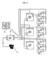
- FIG. 2 is a structural diagram illustrating an airconditioning generation system in accordance with a first preferred embodiment of the present invention.
- the airconditioning generation system in accordance with the first preferred embodiment of the present invention includes 8 indoor units 111, 112, 113, 121, 122, 131, 132, and 133; 3 outdoor units 110, 120, and 130 connected to the eight indoor units 111, 112, 113, 121, 122, 131, 132, and 133; a generator 70 for generating a drive power-supply signal of the indoor and outdoor units by driving an engine; and a distribution unit 80 for dividing a three-phase power-supply signal generated from the generator 70 into individual phase signals, and providing the outdoor or indoor units with the divided phase signals.
- the airconditioning generation system may further include a molded-case circuit breaker 90 connected to the generator 70 and the distribution unit 80. If an unbalanced phase occurs irrespective of operations of the distribution unit 80, the molded-case circuit breaker 90 blocks individual outdoor units 110, 120, and 130 from receiving a power-supply signal.
- the first outdoor unit 110 is connected to three indoor units 111, 112, and 113
- the second outdoor unit 120 is connected to two indoor units 121 and 122
- the third outdoor unit 130 is connected to three indoor units 131 and 132, such that they adjust an amount of a refrigerant flowing in individual indoor units.
- the three-phase power-supply signal generated from the generator 70 is divided into R-, S-, and T-phase signals via the distribution unit 80, and is applied to individual outdoor units 110, 120, and 130. Individual outdoor units transmit the R/S/T-phase power-supply signals to individual indoor units.
- the generator 70 may be implemented with a general three-phase voltage generator capable of providing the indoor units 111, 112, 113, 121, 122, 131, 132, and 133 and the outdoor units 110, 120, and 130 with a power-supply signal.
- a cogeneration system may be used as the generator 70.
- the cogeneration system generates electricity using a cogeneration generator, and uses waste heat of the cogeneration generator.
- the cogeneration system includes an engine, and a cogeneration generator for generating power using rotating force of the engine, and further includes a heat provider.
- the heat provider receives either waste heat of a cooling water of the engine or other waste heat of discharge gas of the engine, and transmits the received heat to a target such as an airconditioner.
- the power generated from the cogeneration generator is used to operate a variety of electric devices such as an electric lamp, and an airconditioner, etc.
- the heat provider receives waste heat of the cooling water of the engine or other waste heat of discharge gas of the engine, such that it performs a hot-water supply operation using the received waste heat or provides the airconditioner with the received waste heat.
- the distribution unit 80 includes a distribution controller 82, which divides the three-phase power-supply signal received from the generator 70 into individual phase signals, transmits the divided phase signals to the outdoor units 110, 120, and 130 and the indoor units 111, 112, 113, 121, 122, 131, 132, and 133, and controls a wiring board to which the three-phase power-supply signal or a single-phase power-supply signal is applied.
- a distribution controller 82 which divides the three-phase power-supply signal received from the generator 70 into individual phase signals, transmits the divided phase signals to the outdoor units 110, 120, and 130 and the indoor units 111, 112, 113, 121, 122, 131, 132, and 133, and controls a wiring board to which the three-phase power-supply signal or a single-phase power-supply signal is applied.
- the distribution unit 80 further includes a sensor 81 for detecting the value of a current signal flowing in the wiring structure capable of providing the indoor and outdoor units with a power-supply signal, such that the distribution controller 82 controls the wiring structure according to the output value of the sensor 81.
- the distribution controller 82 receives the value of a current signal supplied to individual indoor units 111, 112, 113, 121, 122, 131, 132, and 133 and individual outdoor units 110, 120, and 130 from the sensor 81, and calculates the value of a power signal consumed by the indoor and outdoor units in individual phase signals according to the received current value, and controls the wiring structure to establish phase equilibrium in individual phase signals according to the calculated power value.
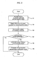
- FIG. 3 is a flow chart illustrating a method for solving an unbalanced phase of the airconditioning generation system in accordance with the first preferred embodiment of the present invention. The method for solving the unbalanced phase of the airconditioning generation system will hereinafter be described with reference to FIG. 3 .
- an engine of the generator 70 is driven to generate a power-supply signal at step S1.
- the power-supply signal is transmitted to the distribution unit 80 connected to the generator 70, and is supplied to the outdoor units.
- the power-supply signal is divided into individual phase signals, such that it is supplied to the indoor units as a single-phase power-supply signal.
- the distribution unit 80 detects the value of a current signal of the power-supply signal transmitted to individual indoor and outdoor units using the sensor 81, calculates the value of consumed power on the basis of the detected current value, and sums the calculated power value in individual phases at step S2.
- each of the indoor units 111, 112, 113, 121, 122, 131, 132, and 133 connected to the outdoor units 110, 120, and 130 consumes predetermined power of 3730 W (5HP), and each outdoor unit consumes predetermined power of 7460 W (10HP)
- power consumed by the first outdoor unit 110 and the indoor units 111, 112, and 113 connected to the first outdoor unit 110 is an R-phase signal having a predetermined power value of 18700 W (25HP)
- power consumed by the second outdoor unit 120 and the indoor units 121, 122, and 123 connected to the second outdoor unit 120 is an S-phase signal having a predetermined power value of 14900 W (20HP)
- power consumed by the third outdoor unit 130 and the indoor units 131, 132, and 133 connected to the third outdoor unit 130 is a T-phase signal having a predetermined power value of 18700 W (25HP).
- the distribution unit 80 detects the value of a current signal of a wiring board receiving the R/S/T-phase power-supply signals, such that it can determine how much R/S/T-phase power-supply signals are supplied to individual indoor and outdoor units in the same manner as in the above-mentioned power consumption calculation method.
- the distribution controller determines the occurrence of the unbalanced phase, and calculates an amount of power to be consumed by individual phase power-supply signals to establish phase equilibrium at steps S3 ⁇ S5.
- a wiring structure of some parts of the indoor or outdoor units is changed according to the amount of the calculated power to establish the phase equilibrium at step S6.
- the R-phase signal consumes the power of 18700 (25HP) the S-phase signal consumes the power of 14900 W (20HP), and the T-phase signal consumes the power of 18700 W (25HP) according to the calculated power consumption of individual phases
- the power consumed by the S-phase signal is relatively less than those of the R-phase and T-phase signals, resulting in the occurrence of an unbalanced phase.
- Each of the R/S/T-phase signals must consume power of 52200 W/3 (70HP/3) to establish the phase equilibrium, such that a wiring structure is controlled to provide the first and third outdoor units with the S-phase power-supply signal suitable for the power of 52200 W/3 (70HP/3).
- the distribution unit 80 repeatedly checks load of individual phases after the phase equilibrium is maintained, and changes the wiring structure to establish the phase equilibrium.
- An airconditioning generation system does not mount the sensor to the distribution unit, and calculates the value of power consumption of individual phases by allowing the distribution unit to communicate with the outdoor units, differently from the above-mentioned airconditioning generation system according to the first preferred embodiment in which the sensor is mounted to the distribution unit.
- FIG. 4 is a structural diagram illustrating the airconditioning generation system in accordance with a second preferred embodiment of the present invention.
- a plurality of indoor units 111, 112, 113, 121, 122, 131, 132, and 133 are connected to outdoor units 10, 20, and 30, and communicate with the outdoor units 10, 20, and 30, such that information associated with power consumption or load are communicated between the indoor units and the outdoor units.
- the indoor units are connected to the outdoor units via a cable, and communicate with the outdoor units according to an RS-485 communication scheme or a power-line communication scheme, such that a variety of wired/wireless communication schemes can be established between the indoor units and the outdoor units to implement an object of the present invention.
- the distribution unit 80' divides a three-phase power-supply signal generated from the generator 70 into individual phase signals, and transmits the divided phase signals to the indoor and outdoor units.
- the distribution unit 80' includes a communication unit 83 communicating with the outdoor units 110, 120, and 130, and a distribution controller 82' for determining the presence or absence of an unbalanced phase on the basis of transmission/reception data of the communication unit 83, and changing a wiring structure according to the determined result associated with the unbalanced phase.
- the airconditioning system composed of the indoor and outdoor units includes a plurality of outdoor units
- at least one outdoor unit is determined to be a master
- the remaining outdoor units are determined to be slaves, such that the slave outdoor units can be centrally controlled according to operation commands of the master outdoor unit.
- the first outdoor unit 110 is determined to be the master outdoor unit
- the second and third outdoor units 120 and 130 are determined to be the slave outdoor units.
- the indoor unit 111 is connected to the outdoor unit 110 according to an RS-485 communication scheme, communicates with the outdoor unit 110, and is controlled by the outdoor unit 110.
- Other indoor units are connected to the indoor unit 111 and the outdoor unit 110 according to the RS-485 communication scheme, and are controlled by the master outdoor unit 110.
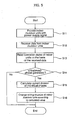
- FIG. 5 is a flow chart illustrating a method for solving an unbalanced phase of the airconditioning generation system shown in FIG. 4 in accordance with the second preferred embodiment of the present invention.
- an engine of a generator is driven to generate a power-supply signal.
- the power-supply signal is transmitted to a distribution unit connected to the generator, and is supplied to the outdoor units. Also, the power-supply signal is divided into individual phase signals, such that it is supplied to indoor units as a single-phase power-supply signal at step S11.
- Individual indoor units or slave outdoor units communicate with a master outdoor unit, and transmits their power consumption data to the master outdoor unit at step S12.
- the distribution unit communicates with the master outdoor unit, such that it receives power consumption data of individual indoor and outdoor units.
- the distribution unit reads the power consumption data, and recognizes the value of power of a three-phase or single-phase power-supply signal consumed by individual indoor and outdoor units at step S13.
- the power values recognized in individual phases are summed, and the magnitudes of the power values are compared with each other, such that the presence or absence of an unbalanced phase can be determined according to the comparison result at step S14.
- the distribution unit changes a wiring structure of the outdoor units or some parts of the outdoor units according to the calculated power value in the same manner as in the first preferred embodiment of the present invention, such that phase equilibrium can be established at steps S15 ⁇ S16.
- the distribution unit repeatedly checks load of individual phases after the phase equilibrium is maintained, and changes a wiring structure to establish the phase equilibrium.
- a wiring structure for providing the outdoor units with a power-supply signal is changed to another wiring structure in which power of 52200 W/3 (70HP/3) is consumed by individual phase signals.
- the S-phase power-supply signal designed to provide the second outdoor unit with a power-supply signal is also applied to the first and third outdoor units, such that power consumption of the S-phase power-supply signal is increased and at the same time other power consumption of the R/T-phase power-supply signals is reduced, resulting in phase equilibrium in three phases.
- an airconditioning generation system and method capable of solving an unbalanced phase includes: one or more indoor units; one or more outdoor units for providing the indoor units with a single-phase power-supply signal; a generator for providing the outdoor units with a power-supply signal; and a distribution unit for checking individual-phase power values consumed by the indoor units, changing a phase of the power-supply signal transmitted from the generator to the outdoor units according to the checked power values, and establishing phase equilibrium in three phases. Therefore, if the unbalanced phase of a three-phase power-supply signal occurs when the power-supply signal is supplied to an airconditioner, the present invention solves the unbalanced phase, such that it prevents a product from being damaged and increases product reliability.
Landscapes
- Engineering & Computer Science (AREA)
- Chemical & Material Sciences (AREA)
- Combustion & Propulsion (AREA)
- Mechanical Engineering (AREA)
- General Engineering & Computer Science (AREA)
- Signal Processing (AREA)
- Human Computer Interaction (AREA)
- Physics & Mathematics (AREA)
- Fuzzy Systems (AREA)
- Mathematical Physics (AREA)
- Power Engineering (AREA)
- Air Conditioning Control Device (AREA)
Claims (14)
- Klimaerzeugungsanlage, die imstande ist, eine unsymmetrische Phase zu beheben, die aufweist:mehrere Inneneinheiten (111, 112, 113, 121, 122, 131, 132, 133); undmehrere Außeneinheiten (110, 120, 130),wobei Energiewerte von Einzelphasenbetriebsenergieversorgungssignalen, die durch die Innen- und Außeneinheiten verbraucht werden, summiert werden, und eine Energieversorgungsverdrahtungsstruktur einiger Teile der Innen- und Außeneinheiten automatisch zu einer anderen Verdrahtungsstruktur geändert wird, wenn eine Differenz der Energieverbrauchswerte von Einzelphasen vorliegt, was zu einem Dreiphasengleichgewicht führt.
- Klimaerzeugungsanlage, die imstande ist, eine unsymmetrische Phase zu beheben, die aufweist:eine Klimaanlage, die eine oder mehrere Inneneinheiten (111, 112, 113, 121, 122, 131, 132, 133) und eine oder mehrere Außeneinheiten (110, 120, 130) aufweist;einen Generator (70) zum Versorgen der Klimaanlage mit einem Betriebsenergieversorgungssignal; undeine Verteilungseinheit (80, 80') zur Ermittlung von Energiewerten von Einzelphasenbetriebsenergieversorgungssignalen der Klimaanlage, Änderung einiger Teile von Phasen des Energieversorgungssignals, das vom Generator (70) zur Klimaanlage übertragen wird, und Herstellung eines Dreiphasengleichgewichts.
- Klimaerzeugungsanlage nach Anspruch 1 oder 2, wobei die Außeneinheiten (110, 120, 130) durch ein Dreiphasenenergieversorgungssignal betrieben werden.
- Klimaerzeugungsanlage nach Anspruch 1, 2 oder 3, wobei die Inneneinheiten (111, 112, 113, 121, 122, 131, 132, 133) durch ein Einphasenenergieversorgungssignal betrieben werden.
- Klimaerzeugungsanlage nach Anspruch 2, 3 oder 4, wobei die Verteilungseinheit (80) aufweist:einen Sensor (81) zur Ermittlung eines Stromsignals, das in einer Verdrahtungsstruktur fließt, die das Energieversorgungssignal vom Generator (70) empfängt und das empfangene Energieversorgungssignal zu den Innen- und Außeneinheiten überträgt; undeine Verteilungssteuereinrichtung (82) zur Berechnung der Summe des Einzelphasenenergieverbrauchs der Innen- und Außeneinheiten gemäß des Ausgangsstromwerts des Sensors (81) und Änderung der Verdrahtungsstruktur zu einer anderen Verdrahtungsstruktur, wenn eine Differenz in der Summe des Einzelphasenenergieverbrauchs vorliegt.
- Anlage nach Anspruch 1, 2, 3, 4 oder 5, wobei die Inneneinheiten mit den Außeneinheiten kommunizieren und die Inneneinheiten (111, 112, 113, 121, 122, 131, 132, 133) Energieverbrauchsdaten zu den Außeneinheiten (110, 120, 130) übertragen.
- Klimaerzeugungsanlage nach Anspruch 6, wobei die Verteilungseinheit (80') aufweist:eine Kommunikationseinheit (83) zur Kommunikation mit den Außeneinheiten (110, 120, 130) und zum Empfangen von Energieverbrauchsdaten der Innen- und Außeneinheiten von den Außeneinheiten; undeine Verteilungssteuereinrichtung (82') zur Berechnung der Summe des Einzelphasenenergieverbrauchs der Innen- und Außeneinheiten und Änderung einer Verdrahtungsstruktur, die zur Übertragung eines Energieversorgungssignals vom Generator (70) zu den Innen- und Außeneinheiten imstande ist, wenn eine Differenz in der Summe des Einzelphasenenergieverbrauchs vorliegt.
- Klimaerzeugungsanlage nach Anspruch 5, 6 oder 7, wobei die Verteilungssteuereinrichtung (82, 82'), wenn eine Differenz im Einzelphasenenergieverbrauch vorliegt, ein Phasenenergieversorgungssignal, das einen kleineren Energieverbrauch aufweist, mit anderen Außeneinheiten oder anderen Inneneinheiten verbindet, und den Energieverbrauch des Phasenenergieversorgungssignals erhöht.
- Anlage nach einem der Ansprüche 1 bis 8, wobei der Generator (70) ein Kraft-Wärme-Kopplungsgenerator ist.
- Verfahren zum Beheben einer unsymmetrischen Phase in einer Klimaerzeugungsanlage, das die Schritte aufweist:a) Berechnen des Energieverbrauchs von Innen- und Außeneinheiten (S1∼S3, S11∼S13);b) Berechnen der Summe der berechneten Energieverbrauchswerte, um das Vorhandensein oder Fehlen der unsymmetrischen Phase (S4, S14) festzustellen; undc) Ändern einer Verdrahtungsstruktur eines Energieversorgungssignals, das den Innen- oder Außeneinheiten zugeführt wird, wenn das Vorhandensein der unsymmetrischen Phase festgestellt wird (S5, S6, S15, S16).
- Verfahren nach Anspruch 10, wobei der Schritt a) die Schritte aufweist:a1) Ermitteln eines Werts eines Stromsignals, das von einem Generator zu den Außen- und Inneneinheiten (S2) übertragen wird; unda2) Berechnen des Energieverbrauchs einzelner Außeneinheiten und Inneneinheiten auf der Grundlage des ermittelten Stromwerts (S3).
- Verfahren nach Anspruch 10 oder 11, wobei der Schritt a) die Schritte aufweist:a3) Übertragen von Daten, die mit dem Energieverbrauch in einem vorgegebenen Bereich verbunden sind, von den Inneneinheiten zu den Außeneinheiten (S12); unda4) Berechnen eines Werts des Energieverbrauchs von einzelnen Innen- und Außeneinheiten auf der Grundlage der von den Außeneinheiten empfangenen Energieverbrauchsdaten (S13).
- Verfahren nach Anspruch 10, 11 oder 12, das ferner die Schritte aufweist:Ermöglichen, daß ein Generator ein Dreiphasenenergieversorgungssignal erzeugt, bevor der Schritt a) ausgeführt wird; undAufteilen des vom Generator erzeugten Dreiphasenenergieversorgungssignals in drei Einphasenenergieversorgungssignale und Versorgen der Außeneinheiten mit den Einphasenenergieversorgungssignalen (S1, S11).
- Verfahren nach Anspruch 13, das ferner den Schritt aufweist:Wiederholen der obigen Schritte, bis die unsymmetrische Phase des Dreiphasenenergieversorgungssignals behoben ist.
Applications Claiming Priority (1)
| Application Number | Priority Date | Filing Date | Title |
|---|---|---|---|
| KR1020040101255A KR100707419B1 (ko) | 2004-12-03 | 2004-12-03 | 상불평형 해소가 가능한 공기조화기 발전시스템 및 그상불평형 해소방법 |
Publications (2)
| Publication Number | Publication Date |
|---|---|
| EP1666807A1 EP1666807A1 (de) | 2006-06-07 |
| EP1666807B1 true EP1666807B1 (de) | 2009-11-04 |
Family
ID=35985369
Family Applications (1)
| Application Number | Title | Priority Date | Filing Date |
|---|---|---|---|
| EP05026398A Expired - Fee Related EP1666807B1 (de) | 2004-12-03 | 2005-12-02 | Klimaerzeugungsanlage zum Ausgleichen einer nicht balancierten Phase und Verfahren dafür |
Country Status (5)
| Country | Link |
|---|---|
| US (1) | US20060144064A1 (de) |
| EP (1) | EP1666807B1 (de) |
| KR (1) | KR100707419B1 (de) |
| CN (1) | CN1808828A (de) |
| DE (1) | DE602005017458D1 (de) |
Families Citing this family (5)
| Publication number | Priority date | Publication date | Assignee | Title |
|---|---|---|---|---|
| JP2008151443A (ja) * | 2006-12-19 | 2008-07-03 | Sanyo Electric Co Ltd | 空気調和システム及びその制御方法 |
| KR101030562B1 (ko) | 2010-06-20 | 2011-04-21 | 주식회사 한일계전 | 배전반 상불평형제거 병렬운전 자동제어 콘트롤러 |
| CN108488914A (zh) * | 2018-04-13 | 2018-09-04 | 珠海格力电器股份有限公司 | 空调机组、空调机组的操作方法和装置 |
| CN110601224B (zh) * | 2019-09-03 | 2023-05-23 | 华南理工大学 | 基于家庭温控负荷的低压台区电压三相不平衡调节方法 |
| JP7665477B2 (ja) | 2021-09-09 | 2025-04-21 | ヤマハ発動機株式会社 | 作業装置、空調設定装置、作業装置群及び空調設定プログラム |
Family Cites Families (28)
| Publication number | Priority date | Publication date | Assignee | Title |
|---|---|---|---|---|
| US3155880A (en) * | 1960-01-27 | 1964-11-03 | Louis E Salina | Phase failure protection for polyphase motors |
| US4078393A (en) * | 1976-01-09 | 1978-03-14 | Borg-Warner Corporation | Control system for controlling the operation of a three-phase load |
| JPS5566294A (en) * | 1978-11-14 | 1980-05-19 | Fuji Electric Co Ltd | Load-balance operation circuit |
| WO1980001742A1 (fr) * | 1979-02-08 | 1980-08-21 | Tatsuta Densen Kk | Detecteur de desequilibre entre phases pour un circuit de charge en courant alternatif |
| US4248054A (en) * | 1979-02-14 | 1981-02-03 | Westinghouse Electric Corp. | Refrigeration system with load balancing control for at least three centrifugal compressors |
| US4433276A (en) * | 1980-10-23 | 1984-02-21 | The United States Of America As Represented By The Administrator Of The National Aeronautics And Space Administration | Three phase power factor controller |
| US4380909A (en) * | 1981-07-17 | 1983-04-26 | Chevron Research Company | Method and apparatus for co-generation of electrical power and absorption-type heat pump air conditioning |
| US4453122A (en) * | 1981-10-19 | 1984-06-05 | Johnson Ewing A | Electrical balancing control for three-phase loads |
| JPS58136931A (ja) * | 1982-02-05 | 1983-08-15 | Hitachi Ltd | 空気調和機の制御方法 |
| JPS59231344A (ja) * | 1983-06-15 | 1984-12-26 | Hitachi Ltd | 空気調和機の制御回路 |
| US4802053A (en) * | 1987-03-11 | 1989-01-31 | Square D Company | Control circuitry including phase failure relay |
| GB2203868B (en) * | 1987-04-16 | 1991-06-26 | Case Group P L C | Power supply control systems |
| JPH03244983A (ja) * | 1990-02-23 | 1991-10-31 | Toshiba Corp | 空気調和機 |
| JP3189398B2 (ja) * | 1992-07-14 | 2001-07-16 | 株式会社明電舎 | 不平衡補償付灯動共用発電装置 |
| JPH06347085A (ja) * | 1993-06-07 | 1994-12-20 | Sanyo Electric Co Ltd | 空気調和機の電源接続構造 |
| JPH07234038A (ja) * | 1994-02-18 | 1995-09-05 | Sanyo Electric Co Ltd | 多室型冷暖房装置及びその運転方法 |
| JP3265803B2 (ja) * | 1994-03-18 | 2002-03-18 | 株式会社日立製作所 | 多室空気調和機及びその制御方法 |
| JPH099487A (ja) * | 1995-06-23 | 1997-01-10 | Sanyo Electric Co Ltd | 空気調和装置の制御装置 |
| US5652505A (en) * | 1995-12-18 | 1997-07-29 | Neilsen-Kuljian, Inc. | Power consumption measurement device for a multiphase alternating current system |
| KR0181399B1 (ko) * | 1996-11-12 | 1999-05-15 | 삼성전자주식회사 | 전압형 pwm 컨버터의 불평형 전원 전압 제어 장치 및 방법 |
| US5995347A (en) * | 1997-05-09 | 1999-11-30 | Texas Instruments Incorporated | Method and apparatus for multi-function electronic motor protection |
| US6643690B2 (en) * | 1998-12-29 | 2003-11-04 | Citrix Systems, Inc. | Apparatus and method for determining a program neighborhood for a client node in a client-server network |
| KR20000012189A (ko) * | 1999-06-10 | 2000-03-06 | 이기표, 박기주 | 지능형모터제어방법 |
| JP4107789B2 (ja) * | 2000-08-10 | 2008-06-25 | 三洋電機株式会社 | 電源逆相検知回路 |
| KR100388655B1 (ko) * | 2001-03-05 | 2003-06-25 | 삼성전자주식회사 | 공기조화기의 제어 시스템 및 그 제어방법 |
| KR200279274Y1 (ko) * | 2002-03-18 | 2002-06-24 | 박세환 | 전류 감시기능 표시장치 |
| JP4129594B2 (ja) * | 2003-04-15 | 2008-08-06 | 株式会社日立製作所 | 空調システム |
| DE602005025068D1 (de) * | 2004-06-21 | 2011-01-13 | Fujitsu Ten Ltd | Gerät zum Korrigieren der Stromwerte eines Drehstrommotors und ein Korrektur-Verfahren |
-
2004
- 2004-12-03 KR KR1020040101255A patent/KR100707419B1/ko not_active Expired - Fee Related
-
2005
- 2005-12-02 US US11/292,085 patent/US20060144064A1/en not_active Abandoned
- 2005-12-02 EP EP05026398A patent/EP1666807B1/de not_active Expired - Fee Related
- 2005-12-02 DE DE602005017458T patent/DE602005017458D1/de not_active Expired - Lifetime
- 2005-12-05 CN CNA2005101295203A patent/CN1808828A/zh active Pending
Also Published As
| Publication number | Publication date |
|---|---|
| US20060144064A1 (en) | 2006-07-06 |
| CN1808828A (zh) | 2006-07-26 |
| DE602005017458D1 (de) | 2009-12-17 |
| KR20060062422A (ko) | 2006-06-12 |
| EP1666807A1 (de) | 2006-06-07 |
| KR100707419B1 (ko) | 2007-04-13 |
Similar Documents
| Publication | Publication Date | Title |
|---|---|---|
| US7739882B2 (en) | Variable speed control | |
| KR101858938B1 (ko) | 공기 조화기 | |
| CN105864970A (zh) | 一种用于调整空调的消耗功率的方法及装置 | |
| CN104272556A (zh) | 与发电机联用的负载切断控制模块 | |
| JPH09294334A (ja) | 系統連系発電機 | |
| KR102024091B1 (ko) | 공기조화기 | |
| EP1666807B1 (de) | Klimaerzeugungsanlage zum Ausgleichen einer nicht balancierten Phase und Verfahren dafür | |
| EP0792002A2 (de) | Generator zur Systemverbindung | |
| US8328110B2 (en) | Electrical load disconnect device with electronic control | |
| US11711911B2 (en) | Three-phase electronic control unit for enclosure air conditioners | |
| KR20050074825A (ko) | 에어컨의 피크전력 제어시스템 및 그 동작방법 | |
| KR20190138059A (ko) | 공기조화기 | |
| KR20190096634A (ko) | 모터 보호 장치를 구비하는 전동기 제어반 | |
| JP3148321B2 (ja) | 空気調和機 | |
| KR101957168B1 (ko) | 공기조화기 | |
| JPS63290342A (ja) | 空気調和機の集中制御装置 | |
| JP3187945B2 (ja) | 空気調和機の総合電流制御システム | |
| CN108565828A (zh) | 共用过载保护的线路及具有该线路的空调机组 | |
| KR20190096633A (ko) | 모터 보호 계전기와 이를 포함하는 모터 보호 시스템 | |
| KR20050105645A (ko) | 역결상 감지회로 및 그 동작방법 | |
| JPH07322493A (ja) | 空気調和機の電源装置 | |
| KR100840938B1 (ko) | 공기조화기 시스템 및 그 제어방법 | |
| JPH03291447A (ja) | 集中制御装置 | |
| JPH0229531A (ja) | 空気調和機の制御装置およびその制御方法 | |
| JPH0237244A (ja) | 空気調和機の集中制御装置およびその集中制御方法 |
Legal Events
| Date | Code | Title | Description |
|---|---|---|---|
| PUAI | Public reference made under article 153(3) epc to a published international application that has entered the european phase |
Free format text: ORIGINAL CODE: 0009012 |
|
| 17P | Request for examination filed |
Effective date: 20060102 |
|
| AK | Designated contracting states |
Kind code of ref document: A1 Designated state(s): AT BE BG CH CY CZ DE DK EE ES FI FR GB GR HU IE IS IT LI LT LU LV MC NL PL PT RO SE SI SK TR |
|
| AX | Request for extension of the european patent |
Extension state: AL BA HR MK YU |
|
| 17Q | First examination report despatched |
Effective date: 20070111 |
|
| AKX | Designation fees paid |
Designated state(s): DE FR GB |
|
| GRAP | Despatch of communication of intention to grant a patent |
Free format text: ORIGINAL CODE: EPIDOSNIGR1 |
|
| RIN1 | Information on inventor provided before grant (corrected) |
Inventor name: RYU, YUN HO Inventor name: CHUNG, BAIK YOUNG Inventor name: LEE, JAE WON Inventor name: CHO, EUN JUN Inventor name: CHOE, YEONG SEOP |
|
| GRAS | Grant fee paid |
Free format text: ORIGINAL CODE: EPIDOSNIGR3 |
|
| RIN1 | Information on inventor provided before grant (corrected) |
Inventor name: RYU, YUN HO Inventor name: CHUNG, BAIK YOUNG Inventor name: LEE, JAE WON Inventor name: CHO, EUN JUN Inventor name: CHOE, YEONG SEOP |
|
| GRAA | (expected) grant |
Free format text: ORIGINAL CODE: 0009210 |
|
| AK | Designated contracting states |
Kind code of ref document: B1 Designated state(s): DE FR GB |
|
| REG | Reference to a national code |
Ref country code: GB Ref legal event code: FG4D |
|
| REF | Corresponds to: |
Ref document number: 602005017458 Country of ref document: DE Date of ref document: 20091217 Kind code of ref document: P |
|
| PGFP | Annual fee paid to national office [announced via postgrant information from national office to epo] |
Ref country code: GB Payment date: 20091231 Year of fee payment: 5 Ref country code: FR Payment date: 20100106 Year of fee payment: 5 |
|
| PGFP | Annual fee paid to national office [announced via postgrant information from national office to epo] |
Ref country code: DE Payment date: 20100129 Year of fee payment: 5 |
|
| PLBE | No opposition filed within time limit |
Free format text: ORIGINAL CODE: 0009261 |
|
| STAA | Information on the status of an ep patent application or granted ep patent |
Free format text: STATUS: NO OPPOSITION FILED WITHIN TIME LIMIT |
|
| 26N | No opposition filed |
Effective date: 20100805 |
|
| GBPC | Gb: european patent ceased through non-payment of renewal fee |
Effective date: 20101202 |
|
| REG | Reference to a national code |
Ref country code: FR Ref legal event code: ST Effective date: 20110831 |
|
| PG25 | Lapsed in a contracting state [announced via postgrant information from national office to epo] |
Ref country code: FR Free format text: LAPSE BECAUSE OF NON-PAYMENT OF DUE FEES Effective date: 20110103 |
|
| REG | Reference to a national code |
Ref country code: DE Ref legal event code: R119 Ref document number: 602005017458 Country of ref document: DE Effective date: 20110701 |
|
| PG25 | Lapsed in a contracting state [announced via postgrant information from national office to epo] |
Ref country code: DE Free format text: LAPSE BECAUSE OF NON-PAYMENT OF DUE FEES Effective date: 20110701 Ref country code: GB Free format text: LAPSE BECAUSE OF NON-PAYMENT OF DUE FEES Effective date: 20101202 |