EP1666821A2 - Kühlschrank und Führungseinrichtung einer Anzeigevorrichtung - Google Patents
Kühlschrank und Führungseinrichtung einer Anzeigevorrichtung Download PDFInfo
- Publication number
- EP1666821A2 EP1666821A2 EP05291771A EP05291771A EP1666821A2 EP 1666821 A2 EP1666821 A2 EP 1666821A2 EP 05291771 A EP05291771 A EP 05291771A EP 05291771 A EP05291771 A EP 05291771A EP 1666821 A2 EP1666821 A2 EP 1666821A2
- Authority
- EP
- European Patent Office
- Prior art keywords
- display device
- receiving portion
- guiding apparatus
- arm assembly
- refrigerator
- Prior art date
- Legal status (The legal status is an assumption and is not a legal conclusion. Google has not performed a legal analysis and makes no representation as to the accuracy of the status listed.)
- Withdrawn
Links
- 230000008878 coupling Effects 0.000 claims description 3
- 238000010168 coupling process Methods 0.000 claims description 3
- 238000005859 coupling reaction Methods 0.000 claims description 3
- 238000007789 sealing Methods 0.000 claims description 3
- 238000003780 insertion Methods 0.000 description 6
- 230000037431 insertion Effects 0.000 description 6
- 230000008901 benefit Effects 0.000 description 5
- 230000008014 freezing Effects 0.000 description 5
- 238000007710 freezing Methods 0.000 description 5
- 238000009413 insulation Methods 0.000 description 4
- 230000002452 interceptive effect Effects 0.000 description 3
- 238000000034 method Methods 0.000 description 3
- 230000004048 modification Effects 0.000 description 3
- 238000012986 modification Methods 0.000 description 3
- 230000002093 peripheral effect Effects 0.000 description 2
- 230000008569 process Effects 0.000 description 2
- 230000006835 compression Effects 0.000 description 1
- 238000007906 compression Methods 0.000 description 1
- 230000005494 condensation Effects 0.000 description 1
- 238000009833 condensation Methods 0.000 description 1
- 230000000881 depressing effect Effects 0.000 description 1
- 230000000994 depressogenic effect Effects 0.000 description 1
- 238000006073 displacement reaction Methods 0.000 description 1
- 230000008020 evaporation Effects 0.000 description 1
- 238000001704 evaporation Methods 0.000 description 1
- 238000009434 installation Methods 0.000 description 1
- 239000004973 liquid crystal related substance Substances 0.000 description 1
- 239000000463 material Substances 0.000 description 1
- 230000007246 mechanism Effects 0.000 description 1
- 239000003507 refrigerant Substances 0.000 description 1
- 238000005057 refrigeration Methods 0.000 description 1
- 230000004044 response Effects 0.000 description 1
- XLYOFNOQVPJJNP-UHFFFAOYSA-N water Substances O XLYOFNOQVPJJNP-UHFFFAOYSA-N 0.000 description 1
- 238000003466 welding Methods 0.000 description 1
Images







Classifications
-
- F—MECHANICAL ENGINEERING; LIGHTING; HEATING; WEAPONS; BLASTING
- F25—REFRIGERATION OR COOLING; COMBINED HEATING AND REFRIGERATION SYSTEMS; HEAT PUMP SYSTEMS; MANUFACTURE OR STORAGE OF ICE; LIQUEFACTION SOLIDIFICATION OF GASES
- F25D—REFRIGERATORS; COLD ROOMS; ICE-BOXES; COOLING OR FREEZING APPARATUS NOT OTHERWISE PROVIDED FOR
- F25D23/00—General constructional features
-
- F—MECHANICAL ENGINEERING; LIGHTING; HEATING; WEAPONS; BLASTING
- F16—ENGINEERING ELEMENTS AND UNITS; GENERAL MEASURES FOR PRODUCING AND MAINTAINING EFFECTIVE FUNCTIONING OF MACHINES OR INSTALLATIONS; THERMAL INSULATION IN GENERAL
- F16M—FRAMES, CASINGS OR BEDS OF ENGINES, MACHINES OR APPARATUS, NOT SPECIFIC TO ENGINES, MACHINES OR APPARATUS PROVIDED FOR ELSEWHERE; STANDS; SUPPORTS
- F16M11/00—Stands or trestles as supports for apparatus or articles placed thereon ; Stands for scientific apparatus such as gravitational force meters
- F16M11/02—Heads
- F16M11/04—Means for attachment of apparatus; Means allowing adjustment of the apparatus relatively to the stand
- F16M11/06—Means for attachment of apparatus; Means allowing adjustment of the apparatus relatively to the stand allowing pivoting
- F16M11/10—Means for attachment of apparatus; Means allowing adjustment of the apparatus relatively to the stand allowing pivoting around a horizontal axis
-
- F—MECHANICAL ENGINEERING; LIGHTING; HEATING; WEAPONS; BLASTING
- F16—ENGINEERING ELEMENTS AND UNITS; GENERAL MEASURES FOR PRODUCING AND MAINTAINING EFFECTIVE FUNCTIONING OF MACHINES OR INSTALLATIONS; THERMAL INSULATION IN GENERAL
- F16M—FRAMES, CASINGS OR BEDS OF ENGINES, MACHINES OR APPARATUS, NOT SPECIFIC TO ENGINES, MACHINES OR APPARATUS PROVIDED FOR ELSEWHERE; STANDS; SUPPORTS
- F16M11/00—Stands or trestles as supports for apparatus or articles placed thereon ; Stands for scientific apparatus such as gravitational force meters
- F16M11/20—Undercarriages with or without wheels
- F16M11/2007—Undercarriages with or without wheels comprising means allowing pivoting adjustment
- F16M11/2035—Undercarriages with or without wheels comprising means allowing pivoting adjustment in more than one direction
- F16M11/2064—Undercarriages with or without wheels comprising means allowing pivoting adjustment in more than one direction for tilting and panning
-
- F—MECHANICAL ENGINEERING; LIGHTING; HEATING; WEAPONS; BLASTING
- F16—ENGINEERING ELEMENTS AND UNITS; GENERAL MEASURES FOR PRODUCING AND MAINTAINING EFFECTIVE FUNCTIONING OF MACHINES OR INSTALLATIONS; THERMAL INSULATION IN GENERAL
- F16M—FRAMES, CASINGS OR BEDS OF ENGINES, MACHINES OR APPARATUS, NOT SPECIFIC TO ENGINES, MACHINES OR APPARATUS PROVIDED FOR ELSEWHERE; STANDS; SUPPORTS
- F16M11/00—Stands or trestles as supports for apparatus or articles placed thereon ; Stands for scientific apparatus such as gravitational force meters
- F16M11/20—Undercarriages with or without wheels
- F16M11/2092—Undercarriages with or without wheels comprising means allowing depth adjustment, i.e. forward-backward translation of the head relatively to the undercarriage
-
- F—MECHANICAL ENGINEERING; LIGHTING; HEATING; WEAPONS; BLASTING
- F16—ENGINEERING ELEMENTS AND UNITS; GENERAL MEASURES FOR PRODUCING AND MAINTAINING EFFECTIVE FUNCTIONING OF MACHINES OR INSTALLATIONS; THERMAL INSULATION IN GENERAL
- F16M—FRAMES, CASINGS OR BEDS OF ENGINES, MACHINES OR APPARATUS, NOT SPECIFIC TO ENGINES, MACHINES OR APPARATUS PROVIDED FOR ELSEWHERE; STANDS; SUPPORTS
- F16M11/00—Stands or trestles as supports for apparatus or articles placed thereon ; Stands for scientific apparatus such as gravitational force meters
- F16M11/20—Undercarriages with or without wheels
- F16M11/24—Undercarriages with or without wheels changeable in height or length of legs, also for transport only, e.g. by means of tubes screwed into each other
-
- F—MECHANICAL ENGINEERING; LIGHTING; HEATING; WEAPONS; BLASTING
- F25—REFRIGERATION OR COOLING; COMBINED HEATING AND REFRIGERATION SYSTEMS; HEAT PUMP SYSTEMS; MANUFACTURE OR STORAGE OF ICE; LIQUEFACTION SOLIDIFICATION OF GASES
- F25D—REFRIGERATORS; COLD ROOMS; ICE-BOXES; COOLING OR FREEZING APPARATUS NOT OTHERWISE PROVIDED FOR
- F25D23/00—General constructional features
- F25D23/02—Doors; Covers
-
- F—MECHANICAL ENGINEERING; LIGHTING; HEATING; WEAPONS; BLASTING
- F25—REFRIGERATION OR COOLING; COMBINED HEATING AND REFRIGERATION SYSTEMS; HEAT PUMP SYSTEMS; MANUFACTURE OR STORAGE OF ICE; LIQUEFACTION SOLIDIFICATION OF GASES
- F25D—REFRIGERATORS; COLD ROOMS; ICE-BOXES; COOLING OR FREEZING APPARATUS NOT OTHERWISE PROVIDED FOR
- F25D29/00—Arrangement or mounting of control or safety devices
- F25D29/005—Mounting of control devices
-
- F—MECHANICAL ENGINEERING; LIGHTING; HEATING; WEAPONS; BLASTING
- F16—ENGINEERING ELEMENTS AND UNITS; GENERAL MEASURES FOR PRODUCING AND MAINTAINING EFFECTIVE FUNCTIONING OF MACHINES OR INSTALLATIONS; THERMAL INSULATION IN GENERAL
- F16M—FRAMES, CASINGS OR BEDS OF ENGINES, MACHINES OR APPARATUS, NOT SPECIFIC TO ENGINES, MACHINES OR APPARATUS PROVIDED FOR ELSEWHERE; STANDS; SUPPORTS
- F16M2200/00—Details of stands or supports
- F16M2200/04—Balancing means
- F16M2200/044—Balancing means for balancing rotational movement of the undercarriage
-
- F—MECHANICAL ENGINEERING; LIGHTING; HEATING; WEAPONS; BLASTING
- F16—ENGINEERING ELEMENTS AND UNITS; GENERAL MEASURES FOR PRODUCING AND MAINTAINING EFFECTIVE FUNCTIONING OF MACHINES OR INSTALLATIONS; THERMAL INSULATION IN GENERAL
- F16M—FRAMES, CASINGS OR BEDS OF ENGINES, MACHINES OR APPARATUS, NOT SPECIFIC TO ENGINES, MACHINES OR APPARATUS PROVIDED FOR ELSEWHERE; STANDS; SUPPORTS
- F16M2200/00—Details of stands or supports
- F16M2200/06—Arms
- F16M2200/065—Arms with a special structure, e.g. reinforced or adapted for space reduction
-
- F—MECHANICAL ENGINEERING; LIGHTING; HEATING; WEAPONS; BLASTING
- F25—REFRIGERATION OR COOLING; COMBINED HEATING AND REFRIGERATION SYSTEMS; HEAT PUMP SYSTEMS; MANUFACTURE OR STORAGE OF ICE; LIQUEFACTION SOLIDIFICATION OF GASES
- F25D—REFRIGERATORS; COLD ROOMS; ICE-BOXES; COOLING OR FREEZING APPARATUS NOT OTHERWISE PROVIDED FOR
- F25D2400/00—General features of, or devices for refrigerators, cold rooms, ice-boxes, or for cooling or freezing apparatus not covered by any other subclass
- F25D2400/36—Visual displays
-
- Y—GENERAL TAGGING OF NEW TECHNOLOGICAL DEVELOPMENTS; GENERAL TAGGING OF CROSS-SECTIONAL TECHNOLOGIES SPANNING OVER SEVERAL SECTIONS OF THE IPC; TECHNICAL SUBJECTS COVERED BY FORMER USPC CROSS-REFERENCE ART COLLECTIONS [XRACs] AND DIGESTS
- Y10—TECHNICAL SUBJECTS COVERED BY FORMER USPC
- Y10S—TECHNICAL SUBJECTS COVERED BY FORMER USPC CROSS-REFERENCE ART COLLECTIONS [XRACs] AND DIGESTS
- Y10S248/00—Supports
- Y10S248/917—Video display screen support
- Y10S248/919—Adjustably orientable video screen support
Definitions
- the present invention relates to a refrigerator and an apparatus for guiding the displacement of a display device installed on a door of the refrigerator.
- the present invention relates to a display device guiding apparatus of a refrigerator, which can prevent a display device mounted on the refrigerator from interfering with an outer wall and other components of the refrigerator by preventing the display device from being inclined in a direction when the display device pivots rightward and leftward, thereby allowing the display device to be smoothly projected frontward.
- the present invention relates to a refrigerator and a display device guiding apparatus of the refrigerator, which allow a user to watch the image displayed on the display device without suffering from or being subjected to a dead (i.e., unviewable) angle and view angle problems.
- a refrigerator includes a main body, a refrigerating compartment for storing food under a refrigeration state and a freezing compartment for storing food under a freezing state.
- the refrigerating and freezing compartments are defined in the main body and selectively opened and closed by refrigerating and freezing doors, respectively.
- the refrigerator is designed to generate cool air using refrigerant going through a series of processes such as compression, condensation, expansion, and evaporation processes. The cool air is supplied to the refrigerating and freezing compartments to lower the temperature therein.
- the user can identify the current state such as the temperature and humidity state of the refrigerator through the display device.
- the user can enjoy a variety of services such as the internet, TV and movie. Therefore, it will be more preferable for the user that a display device as large as possible is installed on the door.
- a flat display device such as a liquid crystal display (LCD) or a plasma display panel (PDP) that is relatively thin is used to prevent the insulation thickness of the door from being reduced.
- LCD liquid crystal display
- PDP plasma display panel
- the flat display device can solve the insulation thickness problem of the door, it may provide a dead angle at which the screen of the display device is hidden by, for example, a door handle and thus the user cannot see the image on the screen of the display device.
- the flat display such as the LCD and PDP has an inherent view angle problem, the user can clearly watch the image on the screen within a predetermined angle range.
- Korean Patent Application No. 10-2000-0033709 discloses a structure for installing the display device on the refrigerator.
- the structure is designed to pivot the display device up and down.
- a thickness of the door is affected in relation to the size of the radius of the curved portion.
- the depth of the receiving portion is increased, the insulating efficiency of the refrigerator is deteriorated. Therefore, an additional insulating member must be further installed.
- the pivotal hinges are formed on left and right sides of the display device, the pivot direction of the display device is limited in a vertical direction. Therefore, the view angle problem in the left and right directions and the dead angle problem caused by the door handle cannot be still solved.
- the present invention is directed to a refrigerator and a display guiding apparatus of the refrigerator that substantially obviate one or more problems due to limitations and disadvantages of the related art.
- An object of the present invention is to provide a refrigerator and a display device guiding apparatus of the refrigerator that can minimize a depth of a display device receiving portion and reduce the insulation loss of a refrigerator door.
- Another object of the present invention is to provide a refrigerator and a display device guiding apparatus of the refrigerator that can solve the view angle problem of a display device in the left and right directions.
- a further another object of the present invention is to provide a refrigerator and a display device guiding apparatus of the refrigerator that can solve a dead angle problem caused by, for example, a door handle.
- a still further other object of the present invention to provide a display device guiding apparatus of a refrigerator, which can prevent a display device mounted on the refrigerator from interfering with an outer wall of the refrigerator and other components such as a door handle of the refrigerator by improving the straight advancement, thereby allowing the user to conveniently use the display device.
- a display device guiding apparatus comprising: a receiving portion in which a display device can be received; and a guide unit provided between the display device and the receiving portion.
- the guide unit comprises: a hinge assembly for pivoting the display at a predetermined angle; an arm assembly having first and second ends respectively connected to the hinge assembly and the receiving portion; and a pivot control unit providing a pivotal force of the arm assembly with respect to the receiving portion.
- a refrigerator comprising: a main body defining a lower temperature space; a door selectively sealing and opening the lower temperature space; a display device that can be received in the receiving portion; a receiving portion formed on the door; a display device that can be received in the receiving portion, and a guide unit is disposed between the display device and the receiving portion.
- the guide unit comprises: an arm assembly having first and second ends respectively connected to the display device and the receiving portion; and a hinge assembly for pivoting the display in vertical and horizontal directions.
- a display device guiding apparatus comprising: a receiving portion for receiving a display device; and a guide unit disposed between the display device and the receiving portion.
- the guide unit comprises: a link assembly having an end fixed on the receiving portion to pivot in a vertical direction; and a hinge assembly controlling an angle of the display device.
- a display device guiding apparatus of a refrigerator comprising: a receiving portion formed on a refrigerator door to selectively receive a display device; a pivot control unit fixed on the receiving portion; an arm assembly having an end hinge-coupled to the fixing panel to pivot in a vertical direction; and a fixing bracket hinge-coupled to the arm assembly and to which the display device is fixed.
- a display device guiding apparatus of a refrigerator comprising: a receiving portion formed on a refrigerator door to selectively receive a display device; a fixing panel fixed on the receiving portion; an arm assembly having an end hinge-coupled to the fixing panel to pivot in a vertical direction; and a spring supported between the arm assembly and the fixing panel.
- a display device guiding apparatus of a refrigerator comprising: a receiving portion formed on a refrigerator door to selectively receive a display device; and a plurality of links each having a first end connected to the receiving portion and a second end connected to the display device, wherein each of the links pivots in a vertical direction around the first end to pivot the display device in the vertical direction.
- the user can more conveniently and safely use the display device.
- the insulating loss caused by the installation of the display device can be reduced.
- FIG. 1 shows a perspective view of a refrigerator according to an embodiment of the present invention.
- a refrigerator 1 includes a door movable for sealing or opening an inner space of the refrigerator 1, a display device 30 formed on a front surface of the door 10, and a door handle 40 used for opening and closing the door. While show in FIG. 1 is a side-by-side refrigerator, the present invention is also applicable to top-freezer and bottom-freezer type refrigerators as well as to any other type of home appliance including a display.
- the user can more conveniently use the refrigerator using images displayed on the display device 30.
- the display device 30 may be used in a state where it is embedded in the door 10 or it is advanced frontward.
- a guide unit 200 is provided between the display device 30 and the door 10.
- FIG. 2 shows a state where the display device is separated from the refrigerator.
- the door 100 of the refrigerator 1 is provided with a receiving portion 20 recessed by a predetermined depth.
- the guide unit 200 is mounted between the receiving portion 20 and the display device 30.
- a fixing bracket 230 is disposed between the guide unit 200 and the display device 30.
- a fixing panel 230 is disposed between the guide unit 200 and the door 10.
- the fixing bracket 230 and/or the fixing panel 240 are not essential in the present invention. For example, opposite ends of the guide unit 200 may be directly fixed on the display device 30 and the door 10, respectively.
- the guide unit 200 will be described in more detail hereinafter.
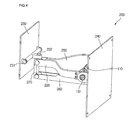
- FIGs. 3 and 4 show a display device guiding apparatus according to an embodiment of the present invention.
- the inventive guiding apparatus includes a guide unit 200, a fixing bracket 230, and a fixing panel 240.
- the guide unit 200 includes an arm assembly 220 disposed between the fixing bracket 230 and the fixing panel 240, a pivot control unit 100 connecting the arm assembly 220 to the fixing panel 240, and an arm assembly cover 250 covering a space defined by the arm assembly.
- the fixing panel 240 is fixed on the door 10 and the pivot control unit 100 is fixed on the fixing panel 240.
- the fixing bracket 230 is advanced frontward, the arm assembly 220 is pivoted around the pivot control unit 100.
- the pivot control unit 100 controls the pivotal motion of the arm assembly 220.
- the fixing bracket 230 has a front surface fixed on a back cover of the display device 30 and a rear surface connected to the arm assembly 220.
- a first hinge shaft 231 allowing the pivotal motion of the display device 30 in a vertical direction and a second hinge shaft 232 allowing the pivotal motion of the display device 30 in a horizontal direction are provided on a connection portion between the arm assembly 220 and the fixing bracket 230.
- the display device 30 can pivots in the vertical and horizontal direction at front ends of the arm assembly 220.
- a tightening unit providing operational friction to the display device 30 may be further provided.
- a link 270 extends downward from the second hinge shaft 232.
- An upper portion of the link 270 is hinge-coupled to the arm assembly 220.
- An arm assembly support 260 may be connected to a lower portion of the link 270 to prevent the arm assembly 220 from excessively pivoting in the vertical direction. That is, the arm assembly support 260 has a front end hinge-coupled to the lower portion of the link 270 and a rear end hinge-coupled to the fixing panel 240.
- the arm assembly 220 pivots together with an operation part of the pivot control unit 100.
- the pivot control unit 100 may be directly fixed on the receiving section 20.
- the pivot control unit 100 is fixed on the fixing panel 240 and the fixing panel 240 is fixed on the receiving section 20.
- the arm assembly support 260, the arm assembly 220, the link 270, and the panel 240 are operated with a four-link articulated structure (i.e., a parallelogram linkage).
- the link 270, the arm assembly support 260, and the panel 240 are hinge-coupled to one another, even when the arm assembly 220 and the arm assembly support 250 pivot in the vertical direction, the link always pivots at a vertical position (i.e., to remain parallel) with respect to the fixing panel 240. Therefore, no view angle problem appears on the display device 30 fixing on the fixing bracket 230.
- the display device 30 pivots in a direction, it does not move in an undesired direction. That is, when the display device 30 is advanced frontward, it pivots around the pivot control unit 100 in a state where it maintains its vertical position.
- the arm assembly 220 includes a pair of right and left arms to stably support the display device against the self-gravity of the display device.
- the arm cover 250 is assembled between the right and left arms 221 and 222 to define a receiving space in which a power line and other input terminals are received without being exposed to an external side.
- the pivot control unit 100 is provided to accurately control the pivot motion of the arm assembly 220.
- the pivot control unit 100 will be described in more detail hereinafter.
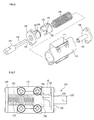
- FIGs. 5 and 6 show the pivot control unit.
- the pivot control unit 100 is installed on the panel 240 and the rear ends of the right and left arms 221 and 222 of the arm assembly 220 are fixed on the pivot control unit 100 by screws 112 (FIG. 4). Therefore, at least one end of the pivot control unit 100 pivots together with the pivotal motion of the arm assembly 220. Other portions of the pivot control unit 100 maintain their fixed states on the fixing panel 240.
- the pivot control unit 100 has at least two parts that are differently operated as described above.
- the pivot control unit 100 includes a cylindrical housing 110, a coupling portion 111 fixed on the panel 240 by screws, a rotational shaft 120 extending from a first end of the housing 110 to fix the arm assembly 220, a first cover 130 covering the first end of the housing 110, and a second cover 140 covering a second end of the housing 110.
- a rotational cam 150 rotating together with the rotational shaft 120 and a spring 160 biasing the rotational cam 150 in a direction.
- the pivot control unit 100 will be described in more detail hereinafter.
- the first and second covers 130 and 140 are assembled on the opposite ends of the housing 110.
- the first cover 130 is provided with a hole through which the rotational shaft 120 is inserted.
- a stationary cam 132 integrally extends from the first cover 130 in a direction where the rotational shaft 120 is inserted.
- the stationary cam 132 is provided at an outer circumference with a cam curve defined by depressing (or recessing) the outer circumference and projections 134 extending from the depressed cam curve.
- the stationary cam 132 and the rotational cam 150 are disposed to correspond to each other, partly contacting each other.
- the rotational cam 150 is provided with a cam curve corresponding to the cam curve of the stationary cam 132.
- the cam curve of the rotational cam 150 is provided at opposite ends with first and second receiving grooves 152 and 154 corresponding to the projections 134 of the stationary cam 132.
- an insertion portion of the rotational shaft 120 penetrates the first cover 130 and the rotational cam 150.
- the insertion portion is provided with a key surface 122 and the rotational cam 150 is provided at a distal end with a hole corresponding to the insertion portion of the rotational shaft 120. Therefore, when the rotational shaft 120 rotates, the rotational cam 150 rotates together therewith. Therefore, a shape of the insertion portion of the rotational shaft 120 is not limited to the above. That is, any shape that can allow the rotational shaft 120 and the rotation cam 150 to integrally rotate may be possible.
- the insertion portion of the rotational shaft 120 may be formed in a polygonal shape or a star shape.
- the rotational shaft 120 and the rotational cam 150 may be fixedly coupled to each other by, for example, welding.
- the spring 160 is supported on the second cover 140 to bias the rotational cam 150 toward the stationary cam 130.
- the spring 160 effectively applies the biasing force in a state where it is supported on the shaft 142 formed on the second cover 140.
- the shaft 142 may be formed as a hollow shaft.
- pivot control unit 100 The operation of the pivot control unit 100 will be described in more detail hereinafter with reference to FIGs. 7 and 8.
- the pivot shaft 120 rotates by the arm assembly 220.
- the rotational cam 150 rotates together with the pivot shaft 120.
- the rotation of the rotational cam 156 is guided by the cam curve formed on the stationary cam 150.
- the projections 134 formed on the stationary cam 132 are guided from the first receiving groove 152 of the rotational cam 150 to the second receiving groove 154.
- the projections 134 are formed corresponding to the first and second receiving grooves 152 and 154 and a connection line between the first and second receiving grooves 152 and 154 are formed with a smooth curve.
- the rotational shaft 120 rotates in the opposite direction, thereby moving the projections 134 from the second receiving portion 154 to the first seating portion.
- FIG. 9 shows the advancing operation of the display device by the inventive display device guiding apparatus.
- the guide unit 200 is received in the receiving portion 20 recessed in the front surface of the door 10.
- the fixing panel 240 is fixed on the inner surface of the receiving portion 20 and the display device is fixed on the fixing bracket 230.
- a flat display device such as an LCD or PDP may be used as the display device.
- the initial state of the guide unit 200 installed on the receiving portion 20 is that the display device 30 is completely received in the receiving portion 20 (see phantom line). In this state, when the user pulls the display device 30 frontward, the display device 30 pivots upward around the pivot shaft 120 installed on the pivot control unit 100.
- the pivot shaft 120 rotates by the arm assembly 220 connected to the fixing bracket 230 fixed to the display device 30.
- the rotational cam 150 rotates together therewith by the key surface 122 formed on the pivot shaft 120.
- the rotation of the pivot shaft 120 is stopped when the projection 134 formed on the stationary cam 132 is received in the second receiving groove 154 formed on the rotational cam 150 and the arm assembly 220 connected to one end of the pivot shaft 120 and the fixing bracket 230 are to be disposed on an identical plane.
- the user can adjust the vertical angle of the display device 30 by pivoting the display device 30 around the first hinge shaft 231.
- the user can adjust the horizontal angle of the display device 30 by pivoting the display device around the second hinge shaft 231.
- the hinge shafts 231 and 232 may be provided with predetermined friction portions so that the adjusted angle of the display device can maintained.
- the user pivots the display device 30 downward, by which the arm assembly 220 rotates the pivot shaft 120.
- the rotational cam 150 moves along the cam curve as the projection 134 of the stationary cam 132 is released from the second receiving groove 154 of the rotational cam 150.
- the projection 134 of the fixing cam 132 is received in the first receiving groove 152 of the rotational cam 150, the display device 30 is to be completely received in the receiving portion 20 of the door 10.
- the display device guiding apparatus can be effectively used when the user intends to more clearly watch the images displayed on the display device when there is the dead angle problem and the view angle problems in a state where the display device 30 is received in the receiving portion 20 of the door 10.
- the display device when it is intended to advance and receive the display device from and in the receiving portion, the display device can be easily advanced and received by the spring 160 installed in the pivot control unit 100 even when the user does not excessively apply the force.
- the display device pivots in a state where it faces forward, it is convenient for the user to adjust the view angle of the display device.
- the display device 30 is fully advanced frontward, since the user can easily adjust the angle of the display device in both the vertical and horizontal direction, the user can clearly watch the images displayed on the display device under any conditions.
- the mounting locations of the hinge shafts 231 and 232 and the shapes of the arm assembly 220 and the cams 132 and 150 are not limited to the embodiment but can be modified.
- the position of the display device can be more variably adjusted.
- the mounting location and shape of the spring 160 can be also modified.
- This embodiment is substantially identical to the first embodiment except for the structure of the guide unit. Therefore, the description of the same parts will be omitted herein.
- FIG. 11 shows a display device guiding apparatus according to a second embodiment of the present invention.
- a display device guiding apparatus includes a fixing panel 310 fixed on the door, a fixing bracket 340 to which the display device is fixed, and a guide unit 300 interconnecting the fixing panel 310 and the fixing bracket 340.
- the guide unit 300 includes an arm assembly having opposite ends respectively hinge-coupled to the fixing panel 310 and the fixing bracket 340 and a spring 330 biasing the arm assembly 320 in a rotational direction.
- a push button switch assembly is installed on a back cover of the display device 30 and the receiving portion 20 of the door 10 to maintain the initial state where the display device 30 is received in the receiving portion 20 of the door 10.
- the push button switch assembly includes a hook (refer to the reference numeral 41 of FIG. 12) and a catch (refer to the reference numeral 42 of FIG. 12), at a position corresponding to the hook 41. Therefore, when the display device 30 is received in the receiving portion 20 of the door 10, the hook 41 is interlocked with the catch 42 to maintain the received state of the display device 30.
- the locations of the hook and the catcher are not limited to this case. It will be sufficient for these two members to be respectively formed on a moving part and a stationary part.
- the hook 41 may be provided on the arm assembly 320 while the catcher 42 is provided on the receiving portion 20. A variety of other modifications will be also possible.
- the push button switch assembly is differently operated according to the number of insertions of the hook 41 into the catch 42. For example, in a state where the hook 41 is interlocked with the catch 42, when the hook 41 is pushed once, the interlocking is released to allow the display device 30 to be advanced frontward. Then, when the hook 41 is pushed into the catch 42 again, the hook 41 is interlocked with the catcher 42. Of course other types of catch or latch mechanisms can also be used. Additionally, it is understood that a similar switch assembly can be used in the first embodiment of the present invention.
- the tension spring 330 disposed between the fixing panel 310 and the arm assembly 320 is provided on at least one of upper and lower portions of the arm assembly 320.
- the tensions of the springs 330 are properly adjusted at the upper and lower portions of the arm assembly 320 so that the display device can be effectively stopped by its self-gravity (or weight) and the tension of the springs.
- FIG. 12 illustrates the operation of this second embodiment.
- the arm assembly 320 pivots upward by the spring 330. Then, in a location where the tension of the spring 330 becomes identical to the self-gravity or weight of the display device, the display device 30 is stopped.
- the display device 30 changes its disposition angle in a desired direction, thereby eliminating the dead angle problem as well as the view angle problem.
- the display device 30 pivots around the hinge shaft 312 so that the push button switch can be interlocked.
- the guide unit of this embodiment can be identically operated to that of the first embodiment where the pivot control unit is installed.
- the display device can be conveniently advanced from and received in the receiving portion.
- This embodiment is substantially identical to the first embodiment except that this embodiment has a feature where the display device can be effectively advanced frontward while overcoming the self-gravity. Therefore, the parts identical to those of the first embodiment will not be described herein.
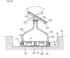
- FIGs. 13 and 14 show a display device guiding apparatus according to a third embodiment of the present invention.
- a back cover of a display device 30 is installed on a front surface of a fixing bracket 410 pivotable in multiple directions.
- a four-link articulated structure 420 is installed in a rear surface of the fixing bracket 410.
- the articulated structure 420 includes a pair of parallel horizontal bars 422 having first and second ends respectively connected to a pair of vertical bars 424 by coupling screws 421 and 430.
- One of the vertical bars 424 is installed in a receiving portion 20 of a door 10.
- a torsion spring 440 is installed on a hinge shaft 431 of the vertical bar 424 fixed in the receiving portion 20.
- a push button switch is provided in order to maintain an initial state where the display device 30 is fully received in the receiving portion 20.
- the push button switch includes a hook 41 and a catch 42.
- the torsion spring applies its biasing force in a direction where the display device 30 is advanced frontward from the receiving portion 20 (in a rotation direction of the horizontal bar 422).
- the torsion spring (or another type of spring) can be installed on any of the other hinge shafts of the articulated structure 420.
- the display device 30 advanced frontward from the receiving portion 20 of the door 10 can be pivoted in the vertical and horizontal directions around hinge shafts so as to provide the clearer image to the user.
- the display device 30 pivots around the hinge shaft 431 so that the push button switch can be interlocked. That is, the vertical bars 424 and the horizontal bares 422 are overlapped with one another, thereby making it possible to minimize the depth of the receiving portion.
- the display device can be easily advanced from the receiving portion and adjusted to provide an optimal view angle and eliminate the dead angle, thereby providing the clearer image to the user.
- the damage of the display device can be prevented in advance.
- the depth of the receiving portion can be minimized, the insulation loss of the door can be reduced.
- the inventive display device guiding apparatus is designed to prevent the display device from interfering with other peripheral parts, it will be more effective to apply the same to the refrigerator door with a handle.
- the feature of the present invention can be preferably applied to a case where the display device is installed on the door of the refrigerator.
- the concept of the present invention can be applied to other electronic devices associated with the display device.
Landscapes
- Engineering & Computer Science (AREA)
- General Engineering & Computer Science (AREA)
- Mechanical Engineering (AREA)
- Chemical & Material Sciences (AREA)
- Combustion & Propulsion (AREA)
- Physics & Mathematics (AREA)
- Thermal Sciences (AREA)
- Cold Air Circulating Systems And Constructional Details In Refrigerators (AREA)
Applications Claiming Priority (1)
| Application Number | Priority Date | Filing Date | Title |
|---|---|---|---|
| KR1020040100663A KR100705069B1 (ko) | 2004-12-02 | 2004-12-02 | 디스플레이의 틸팅 어셈블리 |
Publications (2)
| Publication Number | Publication Date |
|---|---|
| EP1666821A2 true EP1666821A2 (de) | 2006-06-07 |
| EP1666821A3 EP1666821A3 (de) | 2006-08-16 |
Family
ID=35995892
Family Applications (1)
| Application Number | Title | Priority Date | Filing Date |
|---|---|---|---|
| EP05291771A Withdrawn EP1666821A3 (de) | 2004-12-02 | 2005-08-23 | Kühlschrank und Führungseinrichtung einer Anzeigevorrichtung |
Country Status (4)
| Country | Link |
|---|---|
| US (1) | US7546745B2 (de) |
| EP (1) | EP1666821A3 (de) |
| KR (1) | KR100705069B1 (de) |
| CN (1) | CN1783350A (de) |
Cited By (4)
| Publication number | Priority date | Publication date | Assignee | Title |
|---|---|---|---|---|
| NL1035891C (nl) * | 2008-09-03 | 2010-03-16 | Vogel S Holding Bv | Inrichting geschikt voor het ondersteunen van een component. |
| DE102011120713A1 (de) | 2011-12-12 | 2013-06-13 | Deutsche Telekom Ag | Verfahren zur Übermittlung einer Kurznachricht |
| WO2016155805A1 (en) * | 2015-03-31 | 2016-10-06 | Arcelik Anonim Sirketi | Refrigerator with a space-saving and smoothly opening door |
| CN106369257A (zh) * | 2016-10-08 | 2017-02-01 | 青岛海信移动通信技术股份有限公司 | 显示器内嵌固定装置 |
Families Citing this family (76)
| Publication number | Priority date | Publication date | Assignee | Title |
|---|---|---|---|---|
| WO2006068456A1 (en) * | 2004-12-24 | 2006-06-29 | Lg Electronics Inc. | Display unit installing structure for refrigerator |
| US8250163B2 (en) * | 2005-06-09 | 2012-08-21 | Whirlpool Corporation | Smart coupling device |
| US8209398B2 (en) * | 2006-03-16 | 2012-06-26 | Exceptional Innovation Llc | Internet protocol based media streaming solution |
| US8725845B2 (en) * | 2006-03-16 | 2014-05-13 | Exceptional Innovation Llc | Automation control system having a configuration tool |
| US8155142B2 (en) * | 2006-03-16 | 2012-04-10 | Exceptional Innovation Llc | Network based digital access point device |
| US8001219B2 (en) * | 2006-03-16 | 2011-08-16 | Exceptional Innovation, Llc | User control interface for convergence and automation system |
| WO2007124453A2 (en) | 2006-04-20 | 2007-11-01 | Exceptional Innovation Llc | Touch screen for convergence and automation system |
| US7667968B2 (en) * | 2006-05-19 | 2010-02-23 | Exceptional Innovation, Llc | Air-cooling system configuration for touch screen |
| US8382052B1 (en) * | 2006-10-10 | 2013-02-26 | Michael Mathieson | Flat-screen television mounting methods and apparatus |
| US7962130B2 (en) | 2006-11-09 | 2011-06-14 | Exceptional Innovation | Portable device for convergence and automation solution |
| US7618295B2 (en) * | 2007-01-04 | 2009-11-17 | Whirlpool Corporation | Adapter and consumer electronic device functional unit |
| US7765332B2 (en) * | 2007-01-04 | 2010-07-27 | Whirlpool Corporation | Functional adapter for a consumer electronic device |
| US7798865B2 (en) | 2007-01-04 | 2010-09-21 | Whirlpool Corporation | Service supply module and adapter for a consumer electronic device |
| US7870753B2 (en) | 2007-01-04 | 2011-01-18 | Whirlpool Corporation | Appliance door with a service interface |
| US7826203B2 (en) | 2007-01-04 | 2010-11-02 | Whirlpool Corporation | Transformative adapter for coupling a host and a consumer electronic device having dissimilar standardized interfaces |
| US7625246B2 (en) * | 2007-01-04 | 2009-12-01 | Whirlpool Corporation | System for supplying service from an appliance to multiple consumer electronic devices |
| US7810343B2 (en) | 2007-01-04 | 2010-10-12 | Whirlpool Corporation | Dispenser with a service interface for a consumer electronic device |
| US7869201B2 (en) | 2007-01-04 | 2011-01-11 | Whirlpool Corporation | Host and adapter for selectively positioning a consumer electronic display in visible and concealed orientations |
| US7865639B2 (en) | 2007-01-04 | 2011-01-04 | Whirlpool Corporation | Appliance with an electrically adaptive adapter to alternatively couple multiple consumer electronic devices |
| US7686127B2 (en) | 2007-01-04 | 2010-03-30 | Whirlpool Corporation | Acoustic chamber as part of adapter or appliance |
| US8018716B2 (en) | 2007-01-04 | 2011-09-13 | Whirlpool Corporation | Adapter for docking a consumer electronic device in discrete orientations |
| US7871300B2 (en) | 2007-01-04 | 2011-01-18 | Whirlpool Corporation | Host with multiple sequential adapters for multiple consumer electronic devices |
| US8040666B2 (en) * | 2007-01-04 | 2011-10-18 | Whirlpool Corporation | Door with a service interface on an edge |
| US7898812B2 (en) | 2007-01-04 | 2011-03-01 | Whirlpool Corporation | Alternative hosts for multiple adapters and multiple consumer electronic devices |
| US8154857B2 (en) * | 2007-01-04 | 2012-04-10 | Whirlpool Corporation | Appliance host with multiple service interfaces for coupling multiple consumer electronic devices |
| US7980088B2 (en) | 2007-01-04 | 2011-07-19 | Whirlpool Corporation | Removable adapter providing a wireless service to removable consumer electronic device |
| US7651368B2 (en) * | 2007-01-04 | 2010-01-26 | Whirpool Corporation | Appliance with an adapter to simultaneously couple multiple consumer electronic devices |
| US20080164758A1 (en) * | 2007-01-04 | 2008-07-10 | Mccoy Richard A | Electrical accessory charging compartment for a cabinet and retrofit components therefor |
| KR100817238B1 (ko) * | 2007-01-25 | 2008-03-27 | 위니아만도 주식회사 | 식품 저장고 |
| US8074950B2 (en) * | 2007-03-28 | 2011-12-13 | David Michael Clary | Wall affixed vertically articulated flat panel display mount |
| KR100845147B1 (ko) * | 2007-06-13 | 2008-07-09 | 삼성전기주식회사 | 틸팅장치 및 회동장치 |
| US8313072B2 (en) * | 2007-08-27 | 2012-11-20 | Hewlett-Packard Development Company, L. P. | Monitor as a door |
| US8276399B2 (en) * | 2007-09-12 | 2012-10-02 | Whirlpool Corporation | Docking station for a refrigerator |
| US20090127425A1 (en) * | 2007-11-21 | 2009-05-21 | Frazer Daniel S | Refrigerator with display device |
| US8342480B2 (en) * | 2009-12-21 | 2013-01-01 | Whirlpool Corporation | Substance communicating device with mechanically energized connector |
| US8700809B2 (en) * | 2009-12-21 | 2014-04-15 | Whirlpool Corporation | Substance communicating device with activatable connector and cycle structure |
| US8528610B2 (en) * | 2009-12-21 | 2013-09-10 | Whirlpool Corporation | Mechanically energized substance communication coupling system |
| US20110148651A1 (en) * | 2009-12-21 | 2011-06-23 | Whirlpool Corporation | Substance Communicating Device with Sensor Enabled Connector |
| US8439178B2 (en) * | 2009-12-21 | 2013-05-14 | Whirlpool Corporation | Proximity sensor enabled mechanical power coupling system |
| US8387948B2 (en) * | 2009-12-21 | 2013-03-05 | Whirlpool Corporation | Mechanically energized substance communication coupling system |
| US8745203B2 (en) * | 2009-12-21 | 2014-06-03 | Whirlpool Corporation | Mechanical proximity sensor enabled eService connector system |
| US8830660B2 (en) * | 2009-12-21 | 2014-09-09 | Whirlpool Corporation | Mechanical power service communicating device and system |
| US20110148649A1 (en) * | 2009-12-21 | 2011-06-23 | Whirlpool Corporation | Proximity Sensor Enabled Electromagnetic Service Connector System |
| US9103578B2 (en) * | 2009-12-21 | 2015-08-11 | Whirlpool Corporation | Substance communicating device for coupling to a host |
| US8517337B2 (en) * | 2009-12-21 | 2013-08-27 | Whirlpool Corporation | Proximity sensor enabled substance communication coupling system |
| US8430221B2 (en) * | 2009-12-21 | 2013-04-30 | Whirlpool Corporation | Mechanically energized mechanical power coupling system |
| US8382065B2 (en) * | 2009-12-21 | 2013-02-26 | Whirlpool Corporation | Substance communicating device with mechanically energized connector system |
| US8212430B2 (en) * | 2009-12-21 | 2012-07-03 | Whirlpool Corporation | Apparatus and system for communicating electromagnetic service |
| US20110153739A1 (en) * | 2009-12-21 | 2011-06-23 | Whirlpool Corporation | Proximity Sensor Enabled eService Connector System |
| US8405253B2 (en) * | 2009-12-21 | 2013-03-26 | Whirlpool Corporation | Mechanically energized eService connector system |
| US20110148650A1 (en) * | 2009-12-21 | 2011-06-23 | Whirlpool Corporation | Mechanical Proximity Sensor Enabled Electromagnetic Service Connector System |
| US8724037B1 (en) | 2010-06-04 | 2014-05-13 | Kurt William Massey | Mounting system |
| US10281080B1 (en) | 2010-06-04 | 2019-05-07 | Kurt William Massey | Adjustable mounting systems for televisions |
| US9625091B1 (en) | 2014-12-06 | 2017-04-18 | Kurt William Massey | Adjustable mounting systems for televisions |
| CN102346988A (zh) * | 2010-08-03 | 2012-02-08 | 鸿富锦精密工业(深圳)有限公司 | 平面显示装置 |
| US8864092B2 (en) | 2010-08-04 | 2014-10-21 | Brian Newville | Television mount assembly |
| US8827226B2 (en) * | 2010-08-23 | 2014-09-09 | Ergotron, Inc. | Single mount with dual method installation |
| KR102058456B1 (ko) * | 2015-08-31 | 2019-12-23 | 삼성전자주식회사 | 디스플레이 장치 및 이를 포함하는 가전기기 |
| CN106500450B (zh) * | 2016-10-19 | 2020-05-26 | 青岛海尔特种电冰箱有限公司 | 通过预设用户优先级别来操控冰箱显示屏的方法及冰箱 |
| CN106403491B (zh) * | 2016-10-19 | 2019-05-03 | 青岛海尔特种电冰箱有限公司 | 通过麦克风识别以操控冰箱显示屏的方法及冰箱 |
| US10624219B2 (en) * | 2016-10-31 | 2020-04-14 | Michael Sisson | Interactive cabinetry door for use with a cabinet base |
| US12152720B1 (en) | 2017-04-17 | 2024-11-26 | Manehu Product Alliance, Llc | Adjustable mounting systems for televisions |
| US10738941B2 (en) | 2017-09-04 | 2020-08-11 | Manehu Product Alliance, Llc | Display mount assembly |
| US10859201B2 (en) | 2018-04-10 | 2020-12-08 | Manehu Product Alliance, Llc | Display mount assembly |
| KR102528670B1 (ko) * | 2018-07-12 | 2023-05-04 | 엘지전자 주식회사 | 디스플레이 디바이스 |
| US10705574B2 (en) * | 2018-09-24 | 2020-07-07 | Apple Inc. | Accessory devices for portable electronic devices |
| AU2020275763A1 (en) * | 2019-05-13 | 2022-01-06 | Volta Charging, Llc | Charging station with articulating panels |
| KR102873470B1 (ko) | 2019-06-03 | 2025-10-20 | 삼성전자주식회사 | 디스플레이 모듈을 포함하는 가전제품 |
| US11033107B2 (en) | 2019-07-16 | 2021-06-15 | Francis Douglas Warren | Tilting mounting apparatus |
| KR102937688B1 (ko) * | 2019-10-28 | 2026-03-12 | 삼성전자주식회사 | 냉장고 |
| WO2021127552A1 (en) | 2019-12-19 | 2021-06-24 | Manehu Product Alliance, Llc, D/B/A | Adjustable display mounting system |
| WO2021159112A1 (en) | 2020-02-08 | 2021-08-12 | MANEHU PRODUCT ALLIANCE, LLC, d/b/a MANTELMOUNT | Display mounting system with adjustable weight counterbalance |
| CN115398139A (zh) | 2020-02-10 | 2022-11-25 | 显示器产品联盟Dba曼特尔蒙特有限责任公司 | 多方向显示器安装件 |
| US12449192B2 (en) * | 2022-06-03 | 2025-10-21 | RQ Innovasion Inc. | Refrigerator door with an adjustable mirror |
| US12163621B2 (en) | 2022-12-30 | 2024-12-10 | Xinadda (Shen Zhen) Products Co., Ltd | Adjustable mount for display screen |
| US12352705B1 (en) * | 2025-01-10 | 2025-07-08 | Shenzhen Sanyi Technology Co., Ltd. | Pipeline endoscopic mechanism |
Citations (1)
| Publication number | Priority date | Publication date | Assignee | Title |
|---|---|---|---|---|
| KR20010013400A (ko) | 1998-04-04 | 2001-02-26 | 스페리마린인코포레이티드 | 진동 노이즈 감소장치 |
Family Cites Families (11)
| Publication number | Priority date | Publication date | Assignee | Title |
|---|---|---|---|---|
| US419521A (en) * | 1890-01-14 | Mirror supporting and adjusting device | ||
| US4814759A (en) * | 1987-07-08 | 1989-03-21 | Clinicom Incorporated | Flat panel display monitor apparatus |
| US5668570A (en) * | 1993-06-29 | 1997-09-16 | Ditzik; Richard J. | Desktop computer with adjustable flat panel screen |
| JPH0898116A (ja) * | 1994-09-28 | 1996-04-12 | Okamura Corp | テレビ受像機等の支持装置 |
| US6288891B1 (en) * | 1996-11-21 | 2001-09-11 | Canon Kabushiki Kaisha | Movable display apparatus |
| KR100325947B1 (ko) | 1998-11-25 | 2002-09-26 | 대우전자주식회사 | 브이씨알의테이프스타트/앤드센서구동방법 |
| DE10054912C2 (de) * | 2000-02-01 | 2003-03-27 | Lg Electronics Inc | Kühlschrank mit einer als Flüssigkristall ausgebildeten LCD-Anzeige |
| KR100596987B1 (ko) * | 2002-04-19 | 2006-07-04 | 피케이텍시스템 주식회사 | 힌지장치 |
| KR100443618B1 (ko) * | 2002-09-04 | 2004-08-09 | 엘지전자 주식회사 | 영상표시기기의 벽걸이 장치 |
| US6966597B2 (en) * | 2002-12-23 | 2005-11-22 | Tegtmeier Paul H | Tailgate assembly with integral steps |
| US7364127B2 (en) * | 2005-06-07 | 2008-04-29 | Ming-Hua Huang | Support arm for a monitor |
-
2004
- 2004-12-02 KR KR1020040100663A patent/KR100705069B1/ko not_active Expired - Fee Related
-
2005
- 2005-08-23 EP EP05291771A patent/EP1666821A3/de not_active Withdrawn
- 2005-08-24 US US11/209,736 patent/US7546745B2/en not_active Expired - Fee Related
- 2005-09-08 CN CNA2005100999276A patent/CN1783350A/zh active Pending
Patent Citations (1)
| Publication number | Priority date | Publication date | Assignee | Title |
|---|---|---|---|---|
| KR20010013400A (ko) | 1998-04-04 | 2001-02-26 | 스페리마린인코포레이티드 | 진동 노이즈 감소장치 |
Cited By (6)
| Publication number | Priority date | Publication date | Assignee | Title |
|---|---|---|---|---|
| NL1035891C (nl) * | 2008-09-03 | 2010-03-16 | Vogel S Holding Bv | Inrichting geschikt voor het ondersteunen van een component. |
| NL2004332A (nl) * | 2008-09-03 | 2010-06-02 | Vogel S Holding Bv. | Inrichting geschikt voor het ondersteunen van een component |
| DE102011120713A1 (de) | 2011-12-12 | 2013-06-13 | Deutsche Telekom Ag | Verfahren zur Übermittlung einer Kurznachricht |
| WO2016155805A1 (en) * | 2015-03-31 | 2016-10-06 | Arcelik Anonim Sirketi | Refrigerator with a space-saving and smoothly opening door |
| CN106369257A (zh) * | 2016-10-08 | 2017-02-01 | 青岛海信移动通信技术股份有限公司 | 显示器内嵌固定装置 |
| CN106369257B (zh) * | 2016-10-08 | 2019-09-10 | 青岛海信移动通信技术股份有限公司 | 显示器内嵌固定装置 |
Also Published As
| Publication number | Publication date |
|---|---|
| KR100705069B1 (ko) | 2007-04-06 |
| US7546745B2 (en) | 2009-06-16 |
| KR20060062007A (ko) | 2006-06-09 |
| CN1783350A (zh) | 2006-06-07 |
| US20060118694A1 (en) | 2006-06-08 |
| EP1666821A3 (de) | 2006-08-16 |
Similar Documents
| Publication | Publication Date | Title |
|---|---|---|
| US7546745B2 (en) | Refrigerator and display device guiding apparatus of the same | |
| EP1672267A2 (de) | Kühlschrank und seine Bildschirmführungsvorrichtung | |
| US5522656A (en) | Refrigerator door closure system | |
| US8506026B2 (en) | Refrigerator with step adjustment device | |
| US11391074B2 (en) | Door hinge and storage unit including such a door hinge | |
| US7976113B2 (en) | Home bar for refrigerator | |
| US8132876B2 (en) | Refrigerator and door opening apparatus thereof | |
| EP1621839A1 (de) | Kühlschrank und Führungsvorrichtung für Kühlschranksanzeige | |
| US12480705B2 (en) | Refrigerator | |
| US8388077B2 (en) | Refrigerator and hinge assembly of the same | |
| US20220260304A1 (en) | Refrigerator | |
| JP2006322700A (ja) | 貯蔵庫用ヒンジ装置及びこれを備えた貯蔵庫 | |
| KR20180013459A (ko) | 냉장고 및 바스켓 어셈블리 | |
| CN104329880B (zh) | 一种双向开关门装置以及具有该装置的冰箱 | |
| JPH0933162A (ja) | 貯蔵庫 | |
| KR100518689B1 (ko) | 터치 스위치 및 터치 스위치를 구비한 냉장고 | |
| KR20020029506A (ko) | 모니터장치를 갖춘 냉장고 | |
| KR100607678B1 (ko) | 냉장고 | |
| KR0139241Y1 (ko) | 냉장고의 도아힌지장치 | |
| KR20060073224A (ko) | 냉장고의 디스플레이 장착구조 | |
| KR102929915B1 (ko) | 냉장고 및 냉장고 도어 | |
| EP4303508A1 (de) | Türstützfunktion einer kühleinheit | |
| KR100541469B1 (ko) | 착탈 가능한 양방향 개폐 도어 구조 | |
| KR100597679B1 (ko) | 냉장고용 도어지지장치 | |
| KR101252164B1 (ko) | 냉장고용 도어 설치구조 |
Legal Events
| Date | Code | Title | Description |
|---|---|---|---|
| PUAI | Public reference made under article 153(3) epc to a published international application that has entered the european phase |
Free format text: ORIGINAL CODE: 0009012 |
|
| AK | Designated contracting states |
Kind code of ref document: A2 Designated state(s): AT BE BG CH CY CZ DE DK EE ES FI FR GB GR HU IE IS IT LI LT LU LV MC NL PL PT RO SE SI SK TR |
|
| AX | Request for extension of the european patent |
Extension state: AL BA HR MK YU |
|
| PUAL | Search report despatched |
Free format text: ORIGINAL CODE: 0009013 |
|
| AK | Designated contracting states |
Kind code of ref document: A3 Designated state(s): AT BE BG CH CY CZ DE DK EE ES FI FR GB GR HU IE IS IT LI LT LU LV MC NL PL PT RO SE SI SK TR |
|
| AX | Request for extension of the european patent |
Extension state: AL BA HR MK YU |
|
| 17P | Request for examination filed |
Effective date: 20060919 |
|
| 17Q | First examination report despatched |
Effective date: 20061030 |
|
| AKX | Designation fees paid |
Designated state(s): DE ES FR GB NL |
|
| STAA | Information on the status of an ep patent application or granted ep patent |
Free format text: STATUS: THE APPLICATION IS DEEMED TO BE WITHDRAWN |
|
| 18D | Application deemed to be withdrawn |
Effective date: 20110301 |