EP1668764B1 - Pompe rotative a support lcr electromagnetique - Google Patents
Pompe rotative a support lcr electromagnetique Download PDFInfo
- Publication number
- EP1668764B1 EP1668764B1 EP04794058A EP04794058A EP1668764B1 EP 1668764 B1 EP1668764 B1 EP 1668764B1 EP 04794058 A EP04794058 A EP 04794058A EP 04794058 A EP04794058 A EP 04794058A EP 1668764 B1 EP1668764 B1 EP 1668764B1
- Authority
- EP
- European Patent Office
- Prior art keywords
- bearing
- stator
- rotor
- pump
- motor
- Prior art date
- Legal status (The legal status is an assumption and is not a legal conclusion. Google has not performed a legal analysis and makes no representation as to the accuracy of the status listed.)
- Expired - Lifetime
Links
Images


Classifications
-
- F—MECHANICAL ENGINEERING; LIGHTING; HEATING; WEAPONS; BLASTING
- F16—ENGINEERING ELEMENTS AND UNITS; GENERAL MEASURES FOR PRODUCING AND MAINTAINING EFFECTIVE FUNCTIONING OF MACHINES OR INSTALLATIONS; THERMAL INSULATION IN GENERAL
- F16C—SHAFTS; FLEXIBLE SHAFTS; ELEMENTS OR CRANKSHAFT MECHANISMS; ROTARY BODIES OTHER THAN GEARING ELEMENTS; BEARINGS
- F16C32/00—Bearings not otherwise provided for
- F16C32/04—Bearings not otherwise provided for using magnetic or electric supporting means
- F16C32/0406—Magnetic bearings
- F16C32/044—Active magnetic bearings
- F16C32/0459—Details of the magnetic circuit
-
- A—HUMAN NECESSITIES
- A61—MEDICAL OR VETERINARY SCIENCE; HYGIENE
- A61M—DEVICES FOR INTRODUCING MEDIA INTO, OR ONTO, THE BODY; DEVICES FOR TRANSDUCING BODY MEDIA OR FOR TAKING MEDIA FROM THE BODY; DEVICES FOR PRODUCING OR ENDING SLEEP OR STUPOR
- A61M60/00—Blood pumps; Devices for mechanical circulatory actuation; Balloon pumps for circulatory assistance
- A61M60/10—Location thereof with respect to the patient's body
- A61M60/122—Implantable pumps or pumping devices, i.e. the blood being pumped inside the patient's body
- A61M60/165—Implantable pumps or pumping devices, i.e. the blood being pumped inside the patient's body implantable in, on, or around the heart
- A61M60/178—Implantable pumps or pumping devices, i.e. the blood being pumped inside the patient's body implantable in, on, or around the heart drawing blood from a ventricle and returning the blood to the arterial system via a cannula external to the ventricle, e.g. left or right ventricular assist devices
-
- A—HUMAN NECESSITIES
- A61—MEDICAL OR VETERINARY SCIENCE; HYGIENE
- A61M—DEVICES FOR INTRODUCING MEDIA INTO, OR ONTO, THE BODY; DEVICES FOR TRANSDUCING BODY MEDIA OR FOR TAKING MEDIA FROM THE BODY; DEVICES FOR PRODUCING OR ENDING SLEEP OR STUPOR
- A61M60/00—Blood pumps; Devices for mechanical circulatory actuation; Balloon pumps for circulatory assistance
- A61M60/20—Type thereof
- A61M60/205—Non-positive displacement blood pumps
- A61M60/216—Non-positive displacement blood pumps including a rotating member acting on the blood, e.g. impeller
-
- A—HUMAN NECESSITIES
- A61—MEDICAL OR VETERINARY SCIENCE; HYGIENE
- A61M—DEVICES FOR INTRODUCING MEDIA INTO, OR ONTO, THE BODY; DEVICES FOR TRANSDUCING BODY MEDIA OR FOR TAKING MEDIA FROM THE BODY; DEVICES FOR PRODUCING OR ENDING SLEEP OR STUPOR
- A61M60/00—Blood pumps; Devices for mechanical circulatory actuation; Balloon pumps for circulatory assistance
- A61M60/40—Details relating to driving
- A61M60/403—Details relating to driving for non-positive displacement blood pumps
- A61M60/422—Details relating to driving for non-positive displacement blood pumps the force acting on the blood contacting member being electromagnetic, e.g. using canned motor pumps
-
- A—HUMAN NECESSITIES
- A61—MEDICAL OR VETERINARY SCIENCE; HYGIENE
- A61M—DEVICES FOR INTRODUCING MEDIA INTO, OR ONTO, THE BODY; DEVICES FOR TRANSDUCING BODY MEDIA OR FOR TAKING MEDIA FROM THE BODY; DEVICES FOR PRODUCING OR ENDING SLEEP OR STUPOR
- A61M60/00—Blood pumps; Devices for mechanical circulatory actuation; Balloon pumps for circulatory assistance
- A61M60/80—Constructional details other than related to driving
- A61M60/802—Constructional details other than related to driving of non-positive displacement blood pumps
- A61M60/818—Bearings
- A61M60/82—Magnetic bearings
-
- F—MECHANICAL ENGINEERING; LIGHTING; HEATING; WEAPONS; BLASTING
- F04—POSITIVE - DISPLACEMENT MACHINES FOR LIQUIDS; PUMPS FOR LIQUIDS OR ELASTIC FLUIDS
- F04D—NON-POSITIVE-DISPLACEMENT PUMPS
- F04D13/00—Pumping installations or systems
- F04D13/02—Units comprising pumps and their driving means
- F04D13/06—Units comprising pumps and their driving means the pump being electrically driven
- F04D13/0666—Units comprising pumps and their driving means the pump being electrically driven the motor being of the plane gap type
-
- F—MECHANICAL ENGINEERING; LIGHTING; HEATING; WEAPONS; BLASTING
- F04—POSITIVE - DISPLACEMENT MACHINES FOR LIQUIDS; PUMPS FOR LIQUIDS OR ELASTIC FLUIDS
- F04D—NON-POSITIVE-DISPLACEMENT PUMPS
- F04D29/00—Details, component parts, or accessories
- F04D29/04—Shafts or bearings, or assemblies thereof
- F04D29/046—Bearings
- F04D29/048—Bearings magnetic; electromagnetic
-
- F—MECHANICAL ENGINEERING; LIGHTING; HEATING; WEAPONS; BLASTING
- F16—ENGINEERING ELEMENTS AND UNITS; GENERAL MEASURES FOR PRODUCING AND MAINTAINING EFFECTIVE FUNCTIONING OF MACHINES OR INSTALLATIONS; THERMAL INSULATION IN GENERAL
- F16C—SHAFTS; FLEXIBLE SHAFTS; ELEMENTS OR CRANKSHAFT MECHANISMS; ROTARY BODIES OTHER THAN GEARING ELEMENTS; BEARINGS
- F16C32/00—Bearings not otherwise provided for
- F16C32/04—Bearings not otherwise provided for using magnetic or electric supporting means
- F16C32/0406—Magnetic bearings
- F16C32/044—Active magnetic bearings
- F16C32/0474—Active magnetic bearings for rotary movement
- F16C32/0485—Active magnetic bearings for rotary movement with active support of three degrees of freedom
-
- H—ELECTRICITY
- H02—GENERATION; CONVERSION OR DISTRIBUTION OF ELECTRIC POWER
- H02K—DYNAMO-ELECTRIC MACHINES
- H02K21/00—Synchronous motors having permanent magnets; Synchronous generators having permanent magnets
- H02K21/12—Synchronous motors having permanent magnets; Synchronous generators having permanent magnets with stationary armatures and rotating magnets
- H02K21/24—Synchronous motors having permanent magnets; Synchronous generators having permanent magnets with stationary armatures and rotating magnets with magnets axially facing the armatures, e.g. hub-type cycle dynamos
-
- H—ELECTRICITY
- H02—GENERATION; CONVERSION OR DISTRIBUTION OF ELECTRIC POWER
- H02K—DYNAMO-ELECTRIC MACHINES
- H02K7/00—Arrangements for handling mechanical energy structurally associated with dynamo-electric machines, e.g. structural association with mechanical driving motors or auxiliary dynamo-electric machines
- H02K7/08—Structural association with bearings
- H02K7/09—Structural association with bearings with magnetic bearings
-
- H—ELECTRICITY
- H02—GENERATION; CONVERSION OR DISTRIBUTION OF ELECTRIC POWER
- H02K—DYNAMO-ELECTRIC MACHINES
- H02K7/00—Arrangements for handling mechanical energy structurally associated with dynamo-electric machines, e.g. structural association with mechanical driving motors or auxiliary dynamo-electric machines
- H02K7/14—Structural association with mechanical loads, e.g. with hand-held machine tools or fans
-
- A—HUMAN NECESSITIES
- A61—MEDICAL OR VETERINARY SCIENCE; HYGIENE
- A61M—DEVICES FOR INTRODUCING MEDIA INTO, OR ONTO, THE BODY; DEVICES FOR TRANSDUCING BODY MEDIA OR FOR TAKING MEDIA FROM THE BODY; DEVICES FOR PRODUCING OR ENDING SLEEP OR STUPOR
- A61M60/00—Blood pumps; Devices for mechanical circulatory actuation; Balloon pumps for circulatory assistance
- A61M60/10—Location thereof with respect to the patient's body
- A61M60/122—Implantable pumps or pumping devices, i.e. the blood being pumped inside the patient's body
- A61M60/126—Implantable pumps or pumping devices, i.e. the blood being pumped inside the patient's body implantable via, into, inside, in line, branching on, or around a blood vessel
- A61M60/148—Implantable pumps or pumping devices, i.e. the blood being pumped inside the patient's body implantable via, into, inside, in line, branching on, or around a blood vessel in line with a blood vessel using resection or like techniques, e.g. permanent endovascular heart assist devices
-
- F—MECHANICAL ENGINEERING; LIGHTING; HEATING; WEAPONS; BLASTING
- F16—ENGINEERING ELEMENTS AND UNITS; GENERAL MEASURES FOR PRODUCING AND MAINTAINING EFFECTIVE FUNCTIONING OF MACHINES OR INSTALLATIONS; THERMAL INSULATION IN GENERAL
- F16C—SHAFTS; FLEXIBLE SHAFTS; ELEMENTS OR CRANKSHAFT MECHANISMS; ROTARY BODIES OTHER THAN GEARING ELEMENTS; BEARINGS
- F16C2316/00—Apparatus in health or amusement
- F16C2316/10—Apparatus in health or amusement in medical appliances, e.g. in diagnosis, dentistry, instruments, prostheses, medical imaging appliances
- F16C2316/18—Pumps for pumping blood
-
- F—MECHANICAL ENGINEERING; LIGHTING; HEATING; WEAPONS; BLASTING
- F16—ENGINEERING ELEMENTS AND UNITS; GENERAL MEASURES FOR PRODUCING AND MAINTAINING EFFECTIVE FUNCTIONING OF MACHINES OR INSTALLATIONS; THERMAL INSULATION IN GENERAL
- F16C—SHAFTS; FLEXIBLE SHAFTS; ELEMENTS OR CRANKSHAFT MECHANISMS; ROTARY BODIES OTHER THAN GEARING ELEMENTS; BEARINGS
- F16C2360/00—Engines or pumps
- F16C2360/44—Centrifugal pumps
-
- F—MECHANICAL ENGINEERING; LIGHTING; HEATING; WEAPONS; BLASTING
- F16—ENGINEERING ELEMENTS AND UNITS; GENERAL MEASURES FOR PRODUCING AND MAINTAINING EFFECTIVE FUNCTIONING OF MACHINES OR INSTALLATIONS; THERMAL INSULATION IN GENERAL
- F16C—SHAFTS; FLEXIBLE SHAFTS; ELEMENTS OR CRANKSHAFT MECHANISMS; ROTARY BODIES OTHER THAN GEARING ELEMENTS; BEARINGS
- F16C32/00—Bearings not otherwise provided for
- F16C32/04—Bearings not otherwise provided for using magnetic or electric supporting means
- F16C32/0406—Magnetic bearings
- F16C32/0408—Passive magnetic bearings
- F16C32/041—Passive magnetic bearings with permanent magnets on one part attracting the other part
- F16C32/0412—Passive magnetic bearings with permanent magnets on one part attracting the other part for radial load mainly
-
- F—MECHANICAL ENGINEERING; LIGHTING; HEATING; WEAPONS; BLASTING
- F16—ENGINEERING ELEMENTS AND UNITS; GENERAL MEASURES FOR PRODUCING AND MAINTAINING EFFECTIVE FUNCTIONING OF MACHINES OR INSTALLATIONS; THERMAL INSULATION IN GENERAL
- F16C—SHAFTS; FLEXIBLE SHAFTS; ELEMENTS OR CRANKSHAFT MECHANISMS; ROTARY BODIES OTHER THAN GEARING ELEMENTS; BEARINGS
- F16C32/00—Bearings not otherwise provided for
- F16C32/04—Bearings not otherwise provided for using magnetic or electric supporting means
- F16C32/0406—Magnetic bearings
- F16C32/044—Active magnetic bearings
- F16C32/0444—Details of devices to control the actuation of the electromagnets
- F16C32/0446—Determination of the actual position of the moving member, e.g. details of sensors
- F16C32/0448—Determination of the actual position of the moving member, e.g. details of sensors by using the electromagnet itself as sensor, e.g. sensorless magnetic bearings
Definitions
- the present invention relates to a rotary pump with an electromagnetic LCR bearing for supporting the pump rotor.
- Heart disease is the leading cause of death and disability in the United States.
- Some approaches to the treatment of heart disease employ the use of pumping systems that are used to assist the heart in its pumping function, bypass the heart, or replace the heart.
- Such pumping systems may include pumps that are implantable or pumps that remain external to the patient.
- a pumping system is a post-cardiotomy assist system.
- Another example of a pumping system is a bridge-to-transplant system for assisting or replacing a patient's heart while awaiting a transplant.
- a further example of a pumping system is a bridge-to-recovery system, such as a ventricular assist device (VAD), that assists the patient's heart in order to promote myocardial recovery, either spontaneously, with drugs, or with gene therapy.
- VAD ventricular assist device
- the present invention relates to a pump including a housing having a fluid inlet and a fluid outlet.
- a rotor is disposed within the housing and is rotatable about an axis to move fluid from the fluid inlet to the fluid outlet.
- a magnetic axial bearing supports the rotor.
- the axial bearing includes an axial bearing target disposed on the rotor and an axial bearing stator disposed on the housing.
- the axial bearing stator includes multiple stator poles, each of the stator poles including a first coil portion wound in a first direction and a second coil portion wound in a second direction opposite the first direction.
- the present invention also relates to a pump including a housing having a fluid inlet and a fluid outlet.
- a rotor is disposed within the housing and is rotatable about an axis to move fluid from the fluid inlet to the fluid outlet.
- a magnetic first radial bearing exerts a force on the rotor in a first direction along the axis and a magnetic second radial bearing exerts a force on the rotor in a second direction along the axis opposite the first direction.
- the first and second radial bearings are adjustable to allow for independently adjusting the net axial force exerted on the rotor by the radial bearings and the radial stiffness of the radial bearings.
- the present invention also relates to a pump including a housing having a fluid inlet and a fluid outlet.
- a rotor is disposed within the housing and is rotatable about an axis to move fluid from the inlet to the outlet.
- the rotor includes permanent magnets arranged on a first side of the rotor and a magnetically conductive disk arranged on a second side of the rotor opposite the first side of the rotor.
- a motor stator is arranged on the housing to interact with the permanent magnets on the rotor.
- At least one electromagnet is arranged on the housing to interact with the magnetically conductive disk on the rotor.
- At least one ring magnet is arranged on at least one of the first and second sides of the rotor.
- At least one ring magnet is arranged on the housing to magnetically interact with the at least one ring magnet on the rotor.
- the present invention also relates to a pump including a housing having a fluid inlet and a fluid outlet.
- a rotor is disposed within the housing and is rotatable about an axis to move fluid from the inlet to the outlet.
- a motor is arranged to cause rotation of the rotor.
- At least one electromagnet is arranged to interact magnetically with material in the rotor.
- the electromagnet includes a stator formed from a spiral wound lamination material.
- the present invention also relates to a pump including a housing having a fluid inlet and a fluid outlet.
- a rotor is disposed within the housing and is rotatable about an axis to move fluid from the inlet to the outlet.
- a motor is arranged to cause rotation of the rotor.
- At least one electromagnet is arranged to interact magnetically with material in the rotor.
- the electromagnet includes an even number of poles, adjacent poles being wound in opposite directions.
- the present invention also relates to a pump including a housing having a fluid inlet and a fluid outlet.
- a rotor is disposed within the housing and is rotatable about an axis to move fluid from the inlet to the outlet.
- a motor is arranged to cause rotation of the rotor.
- At least one electromagnet is arranged to interact magnetically with material in the rotor.
- the material includes a disk of spiral wound magnetic alloy material.
- the present invention also relates to a method for magnetically supporting a pump rotor in a housing for rotation about an axis.
- the method includes the step of providing an axial bearing target on the rotor.
- the method also includes the step of providing an axial bearing stator on the housing, the axial bearing stator including multiple stator poles, each including a first coil portion and a second coil portion.
- the method also includes the steps of winding the first coil portion in a first direction and winding the second coil portion in a second direction opposite the first direction.
- the present invention further relates to a method for magnetically supporting a pump rotor in a housing for rotation about an axis.
- the method includes the step of providing a magnetic first radial bearing for exerting a force on the rotor in a first direction along the axis.
- the method also includes the step of providing a magnetic second radial bearing for exerting a force on the rotor in a second direction along the axis opposite the first direction.
- the method further includes the step of adjusting the axial positions of the first and second radial bearings to independently adjust the net axial force exerted on the rotor by the radial bearings and the radial stiffness of the radial bearings.
- the present invention relates to a rotary pump that includes magnetic bearings for supporting the pump rotor by magnetically levitating the rotor.
- the pump may comprise a blood pump for incorporation in a system for pumping blood in a patient.
- the pump may be a cardiac assist pump or a cardiac replacement pump.
- the present invention is not necessarily limited to blood pumps and could have alternative implementations or uses in which the pump is used to pump alternative fluids.
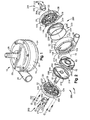
- Figs. 1 and 2 illustrate an example configuration of an apparatus in the form of a pump 10 for pumping fluids.
- the pump 10 may, for example, be a blood pump.
- the pump 10 is a rotary pump in which a rotor assembly or rotor 12 is supported in a housing 14 for rotation about an axis 16.
- the housing 14 includes a central volute housing part 20, a motor stator housing part 22, and an inherently controlled bearing (ICB) stator housing part 24.
- the motor stator housing 22 and ICB housing 24 are connectable to the volute housing 20 on opposite sides of the volute housing, thus forming the assembled condition of the housing 14 shown in Fig. 1 .
- the pump 10 includes an inlet 26, associated with the motor stator housing 22, through which fluid is directed into the pump.
- the pump 10 also includes an outlet 28, associated with the volute housing 20, through which fluid is discharged from the pump.
- the rotor 12 includes an impeller structure 30 that includes a generally disk shaped motor side end wall 32 and a generally disk shaped ICB side end wall 34.
- the end walls 32 and 34 are spaced from each other, parallel to each other, and centered on the axis 16.
- the impeller structure 30 also includes a plurality of impeller vanes 36 that extend between the end walls 32 and 34 and help define a plurality of impeller passages 38.
- a central axially extending inlet passage 40 extends through the rotor 12 is in fluid communication with the impeller passages 38.
- the motor side end wall 32 supports a motor permanent magnet (PM) ring 50 and a motor side PM radial bearing ring 60 of the rotor 12.
- the motor side PM radial bearing ring 60 is positioned radially inward of the motor PM ring 50.
- An annular insulating portion 52 may help isolate the motor PM ring 50 and the motor side PM radial bearing ring 60.
- the motor PM ring 50 and motor side PM radial bearing ring 60 are fixed to or embedded in the motor side end wall 32 of the rotor 12.
- the motor PM ring 50 includes a plurality of PM motor magnets 54 arranged in an annular fashion about the motor side end wall 32. In the embodiment illustrated in Fig.
- the motor PM ring 50 includes eight (8) motor magnets 54 equal in size and arranged spaced evenly in an annular fashion about the motor PM ring 50.
- the motor PM ring 50 could, however, have an alternative configuration, such as including a different number of PM motor magnets 54.
- the motor side PM radial bearing ring 60 may be made of a permanent magnet material with high coercivity such as neodymium boron iron.
- the motor side PM radial bearing ring 60 has an annular single magnet construction.
- the motor side PM radial bearing ring 60 could, however, have an alternative construction.
- the motor side PM radial bearing ring 60 may include multiple magnet segments and may include flux carrying material, such as iron, to aid in creating a desired magnetic flux path.
- the bearing side end wall 34 supports a ring-shaped axial bearing target 70 and a bearing side PM radial bearing ring 80 of the rotor 12.
- the bearing side PM radial bearing ring 80 is positioned radially inward of the axial bearing target 70.
- An annular insulating portion 72 of the bearing side end wall 34 may help isolate the axial bearing target 70 and the bearing side PM radial bearing ring 80.
- the axial bearing target 70 and bearing side PM radial bearing ring 80 are fixed to or embedded in the bearing side end wall 34 of the rotor 12.
- the axial bearing target 70 has an annular configuration and is constructed of ferrite, powder iron, or laminated silicon steel.
- the axial bearing target 70 could be formed from a thin flat strip or strips of material that are wound to form the axial bearing target.
- the axial bearing target 70 could, however, have an alternative configuration, an alternative material construction, or both.
- the bearing side PM radial bearing ring 80 may be made of a permanent magnet material with high coercivity such as neodymium boron iron.
- the bearing side PM radial bearing ring 80 has an annular single magnet construction.
- the bearing side PM radial bearing ring 80 could, however, have an alternative construction.
- the bearing side PM radial bearing ring 80 may include multiple magnet segments and may include flux carrying material, such as iron, to aid in creating a desired magnetic flux path.
- the volute housing part 20 ( Fig. 2 ) has a generally cylindrical main portion 100 that helps define a volute pump chamber 102.
- the main portion 100 has a first end forming a motor side 106 of the volute housing 20 and an opposite second end forming a stator side 108 of the volute housing.
- the pump chamber 102 is sized to receive the rotor 12 and form a predetermined clearance with the rotor.
- An annular pumping channel 104 is formed in the main portion 100 an is in fluid communication with the pump chamber 102 and the impeller passages 38 when the pump 10 is assembled.
- the outlet 28 extends generally tangentially from the main portion 100 of the volute housing part 20 and is in fluid communication with the pumping channel 104.
- the motor stator housing 22 is adapted to support a motor stator assembly 120 of the pump 10.
- the motor stator assembly 120 includes six (6) motor stator coils 122 arranged in an annular configuration.
- Each motor stator coil 122 is made of copper wire that is wound in layers around posts 128 formed on a core 124.
- the core 124 may be formed of a ferromagnetic material, such as a powdered iron material or a silicon steel material, and thereby serve as a flux return path. This may help improve the torque per unit coil current ratio of the pump 10.
- Alternative materials could be used to form the motor stator coils 122, the core 124, or both.
- the motor stator assembly 120 is connected to the motor stator housing 22 by means (not shown) such as an adhesive. Alternative means may be used to secure the motor stator assembly 120 to the motor stator housing 22.
- the motor stator assembly 120, particularly the motor stator coils 122, may also be sealed or covered with a material, such as a film, that is coextensive with an annular inner surface 126 of the motor stator housing 22.
- the assemblage of the motor stator housing 22 and motor stator assembly 120 may thus have a generally flat smooth surface exposed to the pump chamber 102.
- the bearing stator housing 24 is adapted to support an ICB bearing stator assembly 130 of the pump 10.
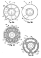
- Alternative embodiments for the bearing stator assembly 130 are illustrated in Figs. 4A and 4B , respectively.
- the bearing stator assembly 130 includes six (6) bearing stator coils 132 arranged in an annular configuration.
- the bearing stator assembly 130 includes three (3) bearing stator coils 132 arranged in an annular configuration.
- each bearing stator coil 132 is made of copper wire that is wound in layers around stator posts 136 on an axial bearing stator core 134.
- the axial bearing stator core 134 may be constructed of a ferromagnetic material and thus may serve as a flux return path. Alternative materials could be used to form the bearing stator coils 132, the axial bearing stator core 134, or both.
- the bearing stator assembly 130 is connected to the bearing stator housing 24 by means (not shown) such as an adhesive. Alternative means may be used to secure the bearing stator assembly 130 to the bearing stator housing 24.
- the bearing stator assembly 130, particularly the bearing stator coils 132, may also be sealed or covered with a material, such as a film, that is coextensive with an annular inner surface 138 of the bearing stator housing 24.
- the assemblage of the bearing stator housing 24 and bearing stator assembly 130 may thus have a generally flat smooth surface exposed to the pump chamber 102.
- the six bearing stator coils 132 of the bearing stator assembly 130 are configured for three phase excitation.
- adjacent pairs of the bearing stator coils 132 are wound with the same wire and excited with the same voltage phase.
- three pairs of bearing stator coils form three bearing coil poles 132a, 132b, and 132c.
- Each bearing stator pole 132a-c can be excited with a different phase of the three phase voltage.
- the individual bearing stator coils 132 of the bearing poles 132a-c may be wound in opposite directions. For example, for each pole 132a-c, one coil 132 may be wound in a clockwise direction and the other coil may be wound in a counterclockwise direction. This is indicated generally by the arrows in Fig. 4A .
- the three bearing stator coils 132 of the bearing stator assembly 130 form three bearing stator poles 132a, 132b, and 132c.
- the three bearing stator poles 132a-c of the bearing stator assembly 130 are configured for three phase excitation. Each bearing stator pole 132a-c can be excited with a different phase of the three phase voltage.
- the pump 10 also includes a motor seal assembly 200 that includes a generally disk shaped motor side seal 202 and a tubular port 204 that projects centrally from the motor side seal.
- the port 204 defines the inlet 26 of the pump 10.
- the motor side seal 202 includes an annular bead 210 that is adapted to be received in an annular shoulder or recess 212 in a motor side surface 214 of the volute housing part 20.
- a generally planar membrane portion 216 extends radially inward from the annular recess 212.
- the motor side seal 202, particularly the membrane portion 216 may be constructed of a sheet of polycarbonate connected to the bead 210 by an adhesive.
- the motor side seal 202 may have a mechanical stiffness derived from radial tensioning of the seal, back support from the motor stator 120, or both.
- the port 204 projects perpendicularly from the membrane portion 216 and extends along the axis 16.
- the port 204 may be connected to the membrane portion 216 by an adhesive.
- the port 204 could project from the membrane at some other angle or could have an extent other than along the axis 16, such as a curved extent.
- an annular projection 208 may project opposite the port 204.
- the projection 208 may help direct fluid flow into the inlet passage 40 of the rotor 12.
- the projection 208 may also serve as a small diameter or small surface area stop point for excessive axial travel of the rotor 12.
- the pump 10 also includes a bearing seal assembly 220 that includes a generally disk shaped bearing side seal 222 and an O-ring 224.
- the bearing side seal 222 includes an annular groove 226 for receiving the O-ring 224.
- the volute housing part 20 may include a similarly or identically configured annular groove (not shown) for receiving the O-ring 224 that is recessed into a bearing side surface 232 of the volute housing part.
- the bearing side seal 222 also includes an annular bead 234 that is adapted to be received in an annular shoulder or recess 236 of the bearing stator housing 24.
- the bearing side seal 222 further includes a generally planar membrane portion 238 extends radially inward from the annular shoulder bead 234.
- the bearing side seal 222 may be constructed of a sheet of adhesive-backed polyester material mounted on the bead 234.
- the bearing side seal 222 may have a mechanical stiffness derived from radial tensioning of the seal, back support from the axial bearing stator 130, or both.
- the pump 10 further includes a PM motor side radial bearing structure 250 connectable with the motor stator housing 22 and a PM bearing side radial bearing structure 252 connectable with the bearing housing 24.
- the motor side radial bearing structure 250 and the bearing side radial bearing structure 252 may be similarly or identically configured.
- each of the radial bearing structures 250 and 252 includes a generally cylindrical PM bearing portion 254 and an annular flange portion 256 that extends radially outward from the PM bearing portion 254.
- the radial bearing structures 250 and 252 could have alternative configurations.
- the diameter and radial thickness of the PM bearing portions 254 may be similar or identical to that of the motor side radial bearing ring 60 and bearing side radial bearing ring 80.
- the PM bearing portions 254 may be made of a permanent magnet material with high coercivity such as neodymium boron iron. Also, the PM bearing portions may include multiple magnet segments and may include flux carrying material, such as iron, to aid in creating a desired magnetic flux path.
- the motor stator assembly 120 is fixed to the motor stator housing 22 and the bearing stator assembly 130 is fixed to the bearing stator housing 24.
- the rotor 12 is positioned in the pump chamber 102 of the volute housing 20 such that the motor side end wall 32 of the impeller structure 30, the motor PM ring 50, and the motor side PM radial bearing ring 60 are positioned adjacent the motor side opening 106 of the volute housing.
- the ICB side end wall 34 of the impeller structure 30, the axial bearing target 70, and the bearing side PM radial bearing ring 80 are positioned adjacent the bearing side opening 108 of the volute housing 20.
- the motor seal assembly 200 is positioned on the volute housing 20 with the annular bead 210 of the motor side seal 202 received in the annular recess 212 of the motor side surface 214.
- the membrane portion 216 of the motor side seal 202 extends radially inward across the motor side opening 106 of the volute housing 20.
- the tubular port 204 projects from the motor side seal 202 along the axis 16.
- the motor stator housing 22 is positioned on the motor side surface 214 such that the port 204 extends through a central opening 260 of the motor stator housing.
- the O-ring 224 is placed in the annular groove 230 of the volute housing 20 and the bearing side seal 222 is placed on the volute housing such that the O-ring is received in the annular groove 226.
- the bearing stator housing 24 is then placed on the bearing side surface 232 of the volute housing 20 such that the annular bead 234 of the bearing side seal 222 is received in the recess 236 of the bearing stator housing.
- the membrane portion 238 of the bearing side seal 222 extends radially inward across the bearing side opening 108 of the volute housing 20.
- Fastening means 262 such as machine screws, are used to secure the motor stator housing 22 and bearing stator housing 24 to the volute housing 20. This clamps the motor side seal 202 between the motor stator housing and the volute housing. This also clamps the bearing side seal 222 between the bearing stator housing and the volute housing.
- the bearing side seal assembly 200 isolates the motor stator assembly 120 from the pump chamber 102 and the bearing side seal assembly 220 isolates the bearing stator assembly 130 from the pump chamber.
- the motor side radial bearing 250 is connected to the motor stator housing 22 via means 270, such as machine screws, that extend through the flange portion 256 of the motor side radial bearing.
- the bearing side radial bearing 252 is connected to bearing housing 24 via means 272, such as machine screws, that extend through the flange portion 256 of the motor side radial bearing.
- Alternative means may be used to secure the radial bearings 250 and 252 to the housing 12.
- the pump 10 illustrated in Figs. 1 and 2 is configured to have reusable parts and disposable parts. This may be a desirable configuration, for example, in the case of a non-implantable blood pump for short-term or medium-term use, such as an assist pump for use in a bridge-to-transplant or bridge-to-recovery scenario. This configuration is provided by the inclusion of the motor side seal assembly 200 and the bearing side seal assembly 220.
- the motor side seal assembly 200 isolates the motor stator assembly 120 and the motor stator housing 22 from the pump chamber 102 and from any fluids (e.g., blood) in the pump chamber. Thus, during use of the pump 10, the motor stator assembly 120 and the motor stator housing 22 are not exposed to pumped fluids and thus may be reusable.
- the bearing side seal assembly 220 isolates the bearing stator assembly 130 and the bearing stator housing 24 from the pump chamber 102 and from pumped fluids in the pump chamber. Thus, during use of the pump 10, the bearing stator assembly 130 and the bearing stator housing 24 are not exposed to pumped fluids and thus may be reusable.
- the volute housing 20, rotor 12, motor side seal assembly 200, and bearing side seal assembly 220 are exposed to pumped fluids and thus may be disposable.
- the pump 10 illustrated in Figs. 1 and 2 may also be configured as a disposable pump that has no reusable parts. This may be a desirable configuration, for example, in the case of an-implantable pump for medium-term or long-term use, such as a heart replacement pump.
- the motor side seal assembly 200 and the bearing side seal assembly 220 may not be required to isolate motor stator assembly 120 and motor stator housing 22 from the pump chamber 102.
- the bearing side seal assembly 220 may not be required to isolate the bearing stator assembly 130 and the bearing stator housing 24 from the pump chamber 102.
- the motor side seal assembly 200 and bearing side seal assembly 220 may not be necessary and can be omitted.
- means such as O-rings or gaskets, may be used to form a seal between the motor side housing 22 and the volute housing 20 and between the bearing side housing 24 and the volute housing.
- the inlet port 204 can be formed integrally with the motor side housing 22, can be fixed to the motor side housing by separate fastening means, or can be fixed to the motor side housing along with the motor side radial bearing 250.
- the operation of the pump 10 is essentially the same, regardless of whether the pump is disposable or has reusable parts.
- the main difference between the configurations is a possible change in the effective magnetic gap between the magnets of the axial and radial bearings caused by the presence or absence of the motor seal assembly 200 and bearing seal assembly 220.
- a motor portion 280 of the pump 10 includes the motor stator assembly 120, the motor side end wall 32 of the rotor 12, and the motor PM ring 50.
- the motor portion 280 is an eight pole, one sided axial gap permanent magnet brushless DC motor.
- the motor portion 280 has six motor stator coils 122 arranged for three phase excitation via, for example, a sinusoidal voltage source. It will be appreciated that alternative configurations for the motor portion 280 may also be implemented.
- a motor side radial bearing 282 of the pump 10 includes the motor side PM radial bearing ring 60 on the rotor 12 and the PM motor side radial bearing structure 250 on the motor stator housing 22.
- a bearing side radial bearing 284 of the pump 10 includes the bearing side PM radial bearing ring 80 on the rotor 12 and the PM bearing side radial bearing structure 252 on the bearing stator housing 24.
- An axial bearing 286 of the pump 10 includes the axial bearing target 70 on the rotor 12 and the ICB bearing stator assembly 130 on the bearing stator housing 24.
- the pump is illustrated schematically in Fig. 6A .
- the magnets of the motor side and bearing side radial bearings 282 and 284 are arranged symmetrically with each other along the axis 16.
- the magnets of the radial bearings 282 and 284 are magnetized in the axial direction (e.g., along the axis 16) and arranged such that the magnets of each bearing are concentric with each other and attract each other.
- the motor side radial bearing ring 60 and the motor side radial bearing structure 250 are concentric with each other and attract each other.
- the bearing side radial bearing ring 80 and the bearing side radial bearing structure 252 are concentric with each other and attract each other.
- the axial bearing 286 helps control the axial linear and tilt positions of the rotor 12 relative to the pump housing 14.
- the position of the rotor 12 may be affected by a variety of factors, such as axial forces imposed on the rotor by the radial bearings 282 and 284, axial forces imposed by the motor portion 280 of the pump 10, fluid flow through the impeller structure 30, and gravity.
- the axial bearing 286, being configured for independent three phase excitation in either the three coil configuration ( Fig. 4B ) or six coil configuration ( Fig. 4A ), helps control the axial position of the rotor 12 along the axis and the tilt position of the rotor relative to the axis. To control the position of the rotor 12 along the axis 16, all three phases may be excited equally. To control the tilt position of the rotor 12 relative to the axis 16, the phases may be excited at different magnitudes.
- the axial bearing 286 is configured such that excitation of the bearing stator coils 132 causes the coils and the axial bearing target 70 to attract each other. Excitation of the axial bearing 286 thus imposes an axial force on the rotor 12 that attracts the rotor toward the bearing stator assembly 130.
- the radial bearings 282 and 284 are configured to impose a net axial force on the rotor 12 in a direction opposite that imposed by the axial bearing 286. The position of the rotor 12 may thus be controlled via excitation of the axial bearing 286 to help maintain the rotor 12 in a desired levitated position.
- Excitation of the axial bearing 286 is controlled via tuned LCR bearing circuits.
- the LCR bearing circuits provide three phase excitation of the axial bearing stator 130.
- Each of the three LCR bearing circuits can be identical, with the exception of the difference of phase shift between the circuits.
- Each axial bearing stator pole 132a-c acts as an electromagnet when excited and thereby attracts the axial bearing target 70.
- Fig. 6A depicts an example of a tuned LCR bearing circuit 300 illustrative of the circuit associated with each of the three axial bearing stator poles 132a-c.
- Each LCR bearing circuit 300 includes a coil 132 of an associated one of the bearing stator poles 132a-c connected in series with a capacitor 302, a resistor 304, and a voltage source 306.
- the resistor 304 could be in the form of a separate resistor component, the inherent resistance of the bearing stator poles, or both.
- the bearing stator poles 132a-c each have an inductance (L), the capacitor 302 has a capacitance (C), and the resistor 304 has a resistance (R).
- the voltage source 306 produces a sinusoidal voltage (E) that excites its associated bearing stator pole.
- the voltage (E) has a fixed frequency ( ⁇ ) that is slightly above a resonant frequency ( ⁇ R ) of the circuit 300.
- the frequency ( ⁇ ) used in the LCR bearing circuit 300 for each coil 132 of the axial bearing 286 may be different. Also, for each LCR bearing circuit 300, different frequencies ( ⁇ ) may be used for start-up and steady state conditions of the pump 10.
- the LCR circuit 300 is used to help suspend the rotor 12 via excitation of its associated bearing stator pole 132a-c of the axial bearing 286.
- the LCR circuit provides self-sensing and self-positioning magnetic suspension of the rotor 12.
- the self-sensing and self-positioning magnetic suspension of the rotor 12 is illustrated in the force versus gap plot of Fig. 6B . Referring to Figs. 6A and 6B , if the rotor 12 moves away from the bearing stator 130, the magnetic gap 310 between the bearing stator and the axial bearing target 70 on the rotor increases and the inductance (L) decreases.
- the resonant frequency ( ⁇ R ) of the circuit 300 increases, thus becoming closer to the excitation frequency ( ⁇ ) of the circuit.
- This causes an increase in the AC current generated by the voltage source 306, which increases the force with which the associated bearing stator pole 132a-c attracts the rotor 12.
- the axial force imposed on the rotor 12 pulls the rotor toward the associated bearing stator pole.
- the magnetic gap 310 decreases and the inductance (L) increases.
- the resonant frequency ( ⁇ R ) of the circuit 300 decreases, thus increasing the difference between the resonant frequency and the excitation frequency ( ⁇ ).
- This causes a decrease in the AC current generated by the voltage source 306, which decreases the force with which the bearing stator pole 132a-c attracts the rotor 12.
- the axial force imposed on the rotor 12 by the bearing stator pole 132a-c is reduced and the axial force imposed on the rotor by the radial bearings 282 and 284 pulls the rotor away from the bearing stator 130.
- the LCR circuits 300 help maintain a fixed gap 310 between the bearing stator poles 132a-c and the axial bearing target 70 and helps maintain the position of the rotor 12.
- the excitation current may be used as an indication of the position of the rotor 12. This is because, as described above, the excitation current of the axial bearing 286 is proportional to the magnetic gap between the bearing stator 130 and the axial bearing target 70. Also, since the poles 132a-c of the axial bearing 286 control both the axial and tilt positions of the rotor 12, the excitation currents may be used to determine both the axial position of the rotor and the tilt position of the rotor.
- the coils 122 of the motor stator 120 are excited via sinusoidal voltage source 292 shown schematically in Fig. 6A , which produces rotation of the rotor 12 and pumping action of the pump 10 in a known manner.
- the fluid to be pumped is drawn into the pump housing 14 ( Fig. 2 ) through the inlet 26 and is directed through the impeller passages 38 into the pump chamber 102.
- the fluid fills the pump chamber 102 and is directed through the outlet 28 via the pumping channel 104.
- the coils 122 of the motor stator 120 are excited with a signal having a frequency in the megahertz range via the sinusoidal voltage source 292.
- the coils 132 of the bearing stator 130 are excited with a signal having a frequency in the hundreds of hertz range via the sinusoidal voltage source 306.
- the motor would thus require a single set of power leads.
- the power could be low pass filtered to the bearing stator coils 132 and either fed directly to or high pass filtered to the motor stator coils 122.
- the fluid in the pump chamber 102 may provide damping for the rotor 12. More particularly, squeeze film damping may occur between the rotor 12 and the motor stator assembly 120 and between the rotor and the bearing stator assembly 130.
- the motor side end wall 32 and bearing side end wall 34 of the rotor may be configured to have a generally flat, smooth surface presented toward the motor stator and bearing stator assemblies 120 and 130, respectively.
- the opposing surfaces of the motor stator assembly 120 and the motor side end wall 32 and the opposing surfaces of the bearing stator assembly 130 and the bearing side end wall 34 and bearing stator assembly 130, being large, flat, smooth, and closely spaced, may help promote the squeeze film damping of the rotor 12.
- the axial bearing stator core 134 may be fabricated by winding a thin flat strip of material in a spiral to form a cylinder. The cylinder is then machined to form the six stator posts 136 around which the wire is wound to form the coils 132.
- the axial bearing target 70 may have a similar wound construction.
- the flat strips of material used to form the axial bearing stator core 134 and axial bearing target 70 can have a high magnetic permeability.
- the flat strips may be formed of a ferrite, powder iron, or laminated silicon steel.
- the adjacent coils 132 wound in opposite directions with the same wire, induce magnetic flux in opposite axial directions in their respective stator posts 136.
- the oppositely wound coils 132 reduce the mutual inductance between the three bearing stator poles 132a-c. This allows the bearing stator poles 132a-c to operate without mutually interfering with each other. This configuration helps reduce the likelihood that a change in current in one of the bearing stator poles 132a-c due to a change in the magnetic gap 310 (see Fig. 6A ) over that particular pole will result in inducing a change in current and force in the other two bearing stator poles.
- the axial bearing stator assembly 130 and the axial bearing target 70 are important elements in the design of the axial bearing 286. It may be desirable that the material used to construct the axial bearing stator core 134 have a high saturation flux density so that the axial force density (i.e., the force per unit of stator volume) capability of the stator assembly 130 is high. It is also desirable the magnetic permeability of the material used to construct the stator core 134 is high to help keep low the coil losses of the axial bearing 286. If the magnetic permeability of the stator core 134 is low, then additional amp-turns must be generated by the axial bearing coils 132 to induce the required level of magnetic flux density in the air gap between the stator 130 and the axial bearing target 70. Higher coil amp-turns require either more current through the same number of coil turns, or the same current though a larger number of coil turns. In either case, the coil i 2 R (power) loss associated with a given coil geometry is increased.
- the axial bearing stator 130 be operated at a flux density sufficiently far removed from magnetic saturation to help avoid detrimental effects on axial bearing behavior that can result from permeability nonlinearities that typically accompany the approach to magnetic saturation.
- the typical rapid decrease in magnetic permeability results in a corresponding decrease in stator leg air gap flux density with an associated decrease in coil self-inductance.
- the decrease in permeability as a material approaches saturation can have an effect similar to an increase in stator to target air gap. Consequently, the rapid drop in permeability as the stator material approaches magnetic saturation can significantly alter the shape of the force characteristic curve shown in Figure 6B , and can result in the bearing being inoperative.
- the axial bearing stator core 134 can be made from a variety of magnetic materials, such as a ferrite material, a sintered iron material, or a high performance metallic lamination.
- Ferrite materials typically have a low saturation flux density (typically 0.4 to 0.5 Tesla), which can limit the flux density generated in the stator to target air gap and thereby can limit the force density of the axial bearing 130.
- Sintered iron material has a flux saturation flux density (typically 0.8 Tesla) greater than that of the ferrite material, but also has a low permeability. The lower permeability of the sintered iron material may require that a high coil current be used in order to take advantage of the higher flux density capability of the sintered iron material.
- a laminated stator material may have both high flux density and high permeability.
- a silicon steel or cobalt iron alloy material can be used to construct an axial bearing stator 130 with both high force density and low coil loss.
- High performance metallic stator materials tend to be good electrical conductors and their use in electrical equipment operating at high frequencies such as those used in the axial bearing 286 may necessitate that the stator materials be laminated in order to reduce eddy current losses. In doing so, it may also be desirable to laminate the stator material in a manner consistent with low manufacturing cost. This can be achieved in various manners.
- the stator materials may be laminated with tapered radial laminations, with laminations bent in a curve similar to a logarithmic spiral, or by spiral winding a thin strip of magnetic material about a cylindrical mandrel into a cylinder pre-machined stator precursor. Spiral winding may be more desirable than tapered laminations and bent curve laminations since the magnetic flux tends to be directed in the circumferential direction in the flux path of the target and in the regions of the stator below the excitation coils.
- the spiral winding approach was used for the fabrication of both the axial bearing stator core 134 and the axial bearing target 70.
- a thin 0.004" by 0.5" wide by 290" long strip of silicon iron was spiral wound about a 0.70" diameter cylindrical mandrel to form a stator precursor. After removal from the mandrel, the upper and lower faces of the resulting spiral wound stator precursor were machined flat. After this machining resulted in a stator cylinder of the correct height, coil slots defining the stator posts 136 were cut into the cylinder using a machining method, such as milling, grinding, or EDM machining.
- the latter method may be preferable since it tends to eliminate smearing of lamination material from lamination to lamination. This smearing can result in local short circuits between laminations which tend to defeat the purpose for using separate thin metallic laminations that are electrically insulated from one another.
- the axial bearing target 70 was fabricated in a similar fashion. A thin, long strip of silicon iron spiral was wound around a cylindrical mandrel to form a target precursor. After removal from the mandrel, the upper and lower faces of the resulting spiral wound target precursor were machined flat to form the target 70. Since the target 70 is in the shape of a simple washer, no additional machining was required after machining its upper and lower surfaces flat and to the associated proper washer height.
- the pump 10 has been illustrated as having a dual radial bearing configuration including the motor side radial bearing 282 and the bearing side radial bearing 284.
- the pump 10 could, however, be configured to have a single radial bearing.
- the bearing side radial bearing 284 could be omitted and the motor side radial bearing 282 could be configured to provide the desired radial stiffness and axial pull to oppose the axial bearing 286.
- the motor side radial bearing 282 could be omitted and the bearing side radial bearing 284 could be configured to provide the desired radial stiffness and axial pull to oppose the axial bearing 286.
- the dual radial bearing configuration can help provide added adjustability.
- the dual radial bearing configuration using the motor side radial bearing 282 and the bearing side radial bearing 284 allows for adjustment of the net axial force imposed on the rotor 12 by the radial bearings independently from the adjustment of the radial stiffness imposed on the rotor by the radial bearings.
- adjustment of the motor side radial bearing 282 and bearing side radial bearing 284 is achieved by adjusting the position of the PM motor side radial bearing structure 250, the PM bearing side radial bearing structure 252, or both. These adjustments may be performed, for example, by adjusting the fastening means 270 and 272 that are used to connect the motor side radial bearing 250 and bearing side radial bearing 252 to the housing 14.
- FIGs. 5A-5C Adjustment of the motor side radial bearing 282 and the bearing side radial bearing 284 is shown in Figs. 5A-5C .
- the motor side radial bearing 282 i.e., the motor side PM radial bearing ring 60 and the PM motor side radial bearing structure 250
- the motor side radial bearing 282 i.e., the motor side PM radial bearing ring 60 and the PM motor side radial bearing structure 250
- the bearing side radial bearing 284 i.e., the bearing side PM radial bearing ring 80 and the PM bearing side radial bearing structure 252 are illustrated schematically.
- the motor side radial bearing 250 and stator side radial bearing 252 are moved either toward or away from each other in equal amounts. This is shown in Fig. 5B .
- the motor side and stator side radial bearings 250 and 252 are moved equal distances toward each other. This is illustrated at 250' and 252' in Fig. 5B .
- the motor side and stator side radial bearings 250 and 252 bearings are moved equal distances away from each other. This is illustrated at 250" and 252" in Fig. 5B .
- the motor side radial bearing 250 and stator side radial bearing 252 are moved relative to the rotor with their position relative to each other remaining unchanged.
- the motor side and stator side radial bearings 250 and 252 are moved equal distances relative to the rotor 12, one bearing moving toward the rotor and the other bearing moving away from the rotor. This is shown in Fig. 5C . Referring to Fig. 5C , to increase the net axial pull of the bearings 282 and 284 in the direction of the arrow in Fig.
- the motor side and stator side radial bearings 250 and 252 are moved toward the positions illustrated at 250' and 250' in Fig. 5C .
- the motor side and stator side radial bearings 250 and 252 are moved toward the positions illustrated at 250" and 252" in Fig. 5C .
- the axial force and radial stiffness are non-linear functions relative to the magnet gap, independent adjustment is possible when the adjustments are small relative to the total gap between magnets (e.g., ⁇ 20%). As the adjustments get larger than this, second-order effects are more pronounced, and the adjustments become less independent.
- the motor side radial bearing 282 and the stator side radial bearing 284 may be offset from each other to help negate an average net hydraulic radial force exerted on the rotor 12. More specifically, the motor side PM radial bearing ring 60, PM motor side radial bearing structure 250, bearing side PM radial bearing ring 80, and the PM bearing side radial bearing structure 252 may be offset relative to each other to exert a radial force on the rotor 12 opposite the average net hydraulic radial force. This may help the rotor 12 to run more centered on the axis 16.
- a rotary pump is constructed in accordance with the present invention.
- the first example pump configuration is of the disposable configuration, omitting the bearing assembly seal and the motor assembly seal, as described above.
- each motor stator coil is made of eight layers of 25-gage copper wire, and occupies 0.16-in of space.
- the motor magnets and coils are positioned on silicon-steel cores that serve as flux return paths.
- the cores are thin, with the intent to choke the flux to help minimize flux changes with motor gap changes. This helps reduce the negative stiffness of the motor.
- the flux density distribution was estimated using a two-dimensional finite element analysis program and the results indicate a calculated peak flux density of 0.25 tesla at the middle of the coil space.
- the calculated motor efficiency is 70% for 5.3-W output at 2,700 rpm and 5 liter/min at 100 mm-Hg.
- the motor input power will be 7.6 W (5 ⁇ 0.70). Allowing approximately 2 W for axial bearing operation, the total power consumption for this first example pump configuration is about 9.6 W.
- the motor efficiency is about 70%, which equates to an overall power consumption of about 20.6 W.
- a single radial bearing design is employed and the pump includes only a bearing side radial bearing, as described above.
- the motor side PM radial bearing ring and the PM motor side radial bearing structure of the radial bearing are axial polarized (1.0-tesla remnant flux density) magnet rings with a 0.55-in. OD and a square cross section of 0.1-in.
- Table 1 Radial Bearing Force and Stiffness Gap, in. F calc , 1b K rcalc, 1b / in . K acalc , 1b/in. K ⁇ calc , 1b-in ./ rad 0.03 2.06 22.3 -44.5 -2.25 0.04 1.67 16.8 -33.6 -1.7 0.05 1.38 13.0 -26.0 -1.32
- the bearing stator assembly has the three bearing stator coil configuration, as described above (see Fig. 4B ).
- the pole area per LCR circuit is approximately 0.190-in. 2
- the coil slot radial width is 0.120-in. 200 turns of 32-gage copper wire were used (0.008-in. copper diameter; 0.009-in. diameter with enamel insulating coating).
- the slot depth is about 0.240-in.
- the wire resistance is approximately 6.9 ohm (R).
- a tuning inductance of 4.66 x 10 -3 Henry (L) calculated at 0.013 in is selected.
- the response peak is wide enough to accommodate 0.010-in. of rotor axial displacement.
- the rotor should be confined in the axial displacement range of ⁇ 0.005-in. from the operating gap at 0.015-in.
- the first example pump configuration allowed 0.010-in. of fluid flow space and 0.005-in. walls. In this range, the average axial stiffness was 26 1b/in. per LCR circuit, or a total of 78 Ib/in.
- the weight of the rotor 12 is estimated to be about 0.083 Ib.
- the axial pull per LCR is calculated to be 0.08 Ib for a total of 0.24 Ib.
- the analysis indicates a power loss of 0.67 W for each of the bearing LCR circuits, or 2.0 W total for the three bearing LCR circuits of the axial bearing stator.
- This coil slot current density is an acceptable value with nominal amounts of fluid cooling.
- the weight (M) of the rotor 12 will be 0.083 Ib.
- the radial bearing is at only one side of the rotor
- the lateral and rocking modes have mixed mode shapes, i.e., mixing with both radial and rocking motions.
- the critical speeds will be influenced by the effective mass added to the impeller as a result of its motion within the fluid being pumped.
- the first example pump configuration exhibited sufficient stiffness in the bearing system to resist imposed shock and vibration loads. Bearing power consumption was below 2.5 W at all operating conditions.
- the pump exhibited the ability to pump 5 liter/min at 100 mm-Hg pressure rise, with a motor input power below 8 W.
- the pump also exhibited the ability to pump 4 liter/min at 350 mm-Hg pressure rise, with motor power below 25 W.
- the pump further exhibited the ability to pump 9 liter/min, 120 mm-Hg pressure rise, with 40-W maximum power.
- the first example pump configuration provided high stiffness, good power efficiency, and high reliability without position sensors or active feedback electronics.
- the inclusion of the LCR axial bearing structure helps eliminate the need for a shaft seal and helps provide a clean wash flow patterns. In a blood pump implementation, this will help reduce the rate of thrombus formation in the pump.
- the magnetic axial bearing is also more durable than the ball bearings or bushings.
- the relatively small size of the pump in the first example configuration (6.4 cm diameter by 3.2 cm thick) may also be desirable.
- a rotary pump is constructed in accordance with the present invention.
- the second example pump configuration is of the reusable configuration and thus includes the bearing assembly seal and the motor assembly seal, as described above.
- the motor stator assembly and axial bearing stator assembly of the second example pump configuration are reusable.
- the pump includes an axial bearing having the six coil configuration of Fig. 4A .
- the rotor diameter is decreased to 1.5 inches in order to reduce viscous drag losses by more than the resulting speed increase, and in order to reduce the motor torque output required for a particular hydraulic output.
- the 6-pole stator core for the axial bearing of the second example pump configuration is made of laminated steel.
- a flat strip or strips of laminated silicon-steel are wound to form an axial bearing target that is fixed to the rotor.
- a strip of laminated silicon-steel that is 0.1-mm thick and 3.0-mm wide may be wound to form a 3.0-mm thick axial bearing target on the rotor.
- Thin-film barriers are used to form the motor seal and bearing seal assemblies that seal the motor stator and axial bearing stator from the rotor.
- the volute design from the implantable pump is modified to accommodate the annular bead in the form of a machined polycarbonate ring.
- a 20-mil-thick (0.25 mm) sheet of polycarbonate forming the membrane portion is glued to the ring and the inlet port is glued to the polycarbonate sheet.
- a 2-mil-thick (0.05 mm) sheet of adhesive-backed polyester material forming the membrane portions is mounted on a metal ring forming the annular bead and the assembly is secured in the stator housing with an O-ring to seal the axial bearing stator from the rotor.
- the axial-gap motor has a measured power capacity of 27 W and a torque constant of approximately 0.01 Nm/A.
- the entire motor core, including the posts, is made of powdered iron so as to reduce eddy current loss.
- the iron posts form a part of the flux return path formed by the core of the motor. Without the posts, the magnetic flux would flow evenly between the magnets and the core. With the posts, the flux tends to concentrate and pass through the bearing coils. In this way, the posts serve to increase the magnetic flux link of the coils and thus produce more torque per unit of coil current. Since the motor PM ring on the rotor has eight poles, the magnetic flux in the core fluctuates at a frequency of 500 Hz or higher.
- the poles on the core may also increase the negative axial and angular stiffness on the rotor.
- the negative axial stiffness can be compensated for by the use of higher coil currents.
- Maintenance of the angular stiffness requires more "moment arm,” or radial distance between the bearing poles and bearing center, because the positive angular stiffness is proportional to the square of the distance. Therefore, to compensate for the angular stiffness by increasing the moment arm, the bearing core pole areas in the ICB were moved out radially.
- Laminated silicon steel is used to form the axial bearing stator and the axial bearing PM ring on the rotor.
- the dual radial bearing design (see Figs. 5A-5C ) is employed.
- the second example pump configuration thus includes both a motor side radial bearing and a bearing side radial bearing.
- the second example pump configuration was run safely at a maximum power of approximately 40 W without overheating the motor coils. Loss data was calculated from observed peak-to-peak values of the bearing sinusoidal currents, and the coil resistance of 3.8 ohms per LCR bearing circuit. The maximum recorded bearing power loss is identified as 1.7 W. Considering the eddy current and hysteresis loss of laminated-silicon-steel bearing cores, it was observed that, at approximately 900 Hz (the LCR bearing circuit excitation frequency) and an average estimated flux density of 4 kilogauss in the cores, the loss is approximately 1.0 W/1b of core material. Since the second example pump configuration includes about 0.12 lb of laminated cores, an additional loss of 0.12 W was estimated. Therefore, the total bearing loss for the second example pump configuration for all operating conditions is calculated at no more than 1.82 W (1.7+0.12).
- the second example pump configuration thus demonstrates sufficient stiffness in the radial and axial bearings.
- the pump also exhibited the ability to pump 5 liter/min at 100 mm Hg pressure rise, with motor power input below 8 W; the ability to pump 4 liter/min at 350 mm Hg pressure rise, with motor power below 25 W; and the ability to pump 9 liter/min, 120 mm Hg pressure rise, with 40-W maximum power.
Landscapes
- Engineering & Computer Science (AREA)
- Health & Medical Sciences (AREA)
- Heart & Thoracic Surgery (AREA)
- Mechanical Engineering (AREA)
- General Engineering & Computer Science (AREA)
- Cardiology (AREA)
- Anesthesiology (AREA)
- Biomedical Technology (AREA)
- Life Sciences & Earth Sciences (AREA)
- Animal Behavior & Ethology (AREA)
- General Health & Medical Sciences (AREA)
- Public Health (AREA)
- Veterinary Medicine (AREA)
- Hematology (AREA)
- Power Engineering (AREA)
- Electromagnetism (AREA)
- Physics & Mathematics (AREA)
- Structures Of Non-Positive Displacement Pumps (AREA)
- Magnetic Bearings And Hydrostatic Bearings (AREA)
- Connection Of Motors, Electrical Generators, Mechanical Devices, And The Like (AREA)
- External Artificial Organs (AREA)
- Permanent Magnet Type Synchronous Machine (AREA)
- Rotary Pumps (AREA)
Claims (7)
- Pompe comprenant:un logement ayant un orifice d'entrée de fluide et un orifice de sortie de fluide ;un rotor disposé dans le logement et rotatif autour d'un axe pour déplacer le fluide de l'orifice d'entrée de fluide vers orifice de sortie de fluide ; etun support axial magnétique pour supporter le rotor, le support axial comprenant une cible de support axial disposée sur le rotor et un stator de support axial disposé sur le logement, le stator de support axial comprenant de multiples pôles de stator, chacun des pôles de stator comprenant une première partie de bobine enroulée dans une première direction et une seconde partie de bobine enroulée dans une seconde direction opposée à la première direction.
- Pompe selon la revendication 1, dans laquelle la première direction se fait dans le sens des aiguilles d'une montre et la seconde direction se fait dans le sens inverse des aiguilles d'une montre.
- Pompe selon la revendication 1, dans laquelle chacun des multiples pôles de stator comprend un électroaimant ayant une inductance (L), l'électroaimant étant connecté en série avec une résistance (R), une capacité (C) et une source de tension de phase pour former un circuit LCR pour commander le support axial.
- Pompe selon la revendication 1, dans laquelle le stator de support comprend trois pôles de stator, chaque pôle de stator comprenant une première bobine enroulée selon une configuration dans les sens des aiguilles d'une montre et une seconde bobine enroulée selon une configuration dans le sens inverse des aiguilles d'une montre, chacun des pôles de stator étant excité par une phase électrique correspondante d'une source de tension triphasée.
- Pompe selon la revendication 1, dans laquelle le stator de support axial comprend une bande de matériau enroulée dans une bobine cylindrique et usinée pour former un noyau de stator comprenant des montants de stator autour desquels les première et seconde bobines de chaque pôle de stator sont enroulées.
- Pompe selon la revendication 1, comprenant en outre :un premier support radial magnétique pour exercer une force sur le rotor dans une première direction le long de l'axe; etun second support radial magnétique pour exercer une force sur le rotor dans une seconde direction le long de l'axe opposé à la première direction;les premier et second supports radiaux étant ajustables pour permettre l'ajustement de la force axiale nette exercée sur le rotor par les supports radiaux indépendamment de la rigidité radiale des supports radiaux.
- Pompe selon la revendication 1, dans laquelle le stator de support axial est excité par une tension superposée sur une tension fournie à un stator de moteur de la pompe.
Applications Claiming Priority (2)
| Application Number | Priority Date | Filing Date | Title |
|---|---|---|---|
| US50861803P | 2003-10-03 | 2003-10-03 | |
| PCT/US2004/032560 WO2005034312A2 (fr) | 2003-10-02 | 2004-10-01 | Pompe rotative a support lcr electromagnetique |
Publications (2)
| Publication Number | Publication Date |
|---|---|
| EP1668764A2 EP1668764A2 (fr) | 2006-06-14 |
| EP1668764B1 true EP1668764B1 (fr) | 2008-08-27 |
Family
ID=34421766
Family Applications (1)
| Application Number | Title | Priority Date | Filing Date |
|---|---|---|---|
| EP04794058A Expired - Lifetime EP1668764B1 (fr) | 2003-10-03 | 2004-10-01 | Pompe rotative a support lcr electromagnetique |
Country Status (6)
| Country | Link |
|---|---|
| US (1) | US20050147512A1 (fr) |
| EP (1) | EP1668764B1 (fr) |
| JP (1) | JP2007518464A (fr) |
| AT (1) | ATE406685T1 (fr) |
| DE (1) | DE602004016188D1 (fr) |
| WO (1) | WO2005034312A2 (fr) |
Families Citing this family (62)
| Publication number | Priority date | Publication date | Assignee | Title |
|---|---|---|---|---|
| US7232292B2 (en) * | 2001-08-21 | 2007-06-19 | Rotys Inc. | Integrated motorized pump |
| CA2610379A1 (fr) * | 2005-05-27 | 2006-12-07 | The Cleveland Clinic Foundation | Procede et appareil de compensation de courants de foucault dans une sonde radioelectrique |
| US20090162225A1 (en) * | 2007-12-20 | 2009-06-25 | Fu Zhun Precision Industry (Shen Zhen) Co., Ltd. | Pump for liquid cooling system |
| US20090169399A1 (en) * | 2007-12-27 | 2009-07-02 | Metal Industries Research&Development Centre | Ultra-thin miniature pump |
| EP2292282B1 (fr) | 2008-06-23 | 2017-11-15 | Thoratec Corporation | Pompe à sang |
| ITPN20080051A1 (it) | 2008-06-24 | 2009-12-25 | Mate S A S | Macchina operatrice, in particolare una motopompa a motore assiale |
| CN102239334B (zh) | 2008-12-08 | 2015-03-04 | 胸腔科技有限公司 | 离心式泵装置 |
| JP5378010B2 (ja) | 2009-03-05 | 2013-12-25 | ソラテック コーポレーション | 遠心式ポンプ装置 |
| CN102341600B (zh) * | 2009-03-06 | 2014-12-10 | 胸腔科技有限公司 | 离心式泵装置 |
| CN101885325A (zh) * | 2009-05-12 | 2010-11-17 | 德昌电机(深圳)有限公司 | 一种防抱死制动系统及其电机 |
| EP3490122B1 (fr) | 2009-07-29 | 2021-01-27 | Thoratec Corporation | Dispositif de mise en rotation et dispositif de pompe centrifuge |
| JP5443197B2 (ja) | 2010-02-16 | 2014-03-19 | ソラテック コーポレーション | 遠心式ポンプ装置 |
| WO2011118325A1 (fr) | 2010-03-26 | 2011-09-29 | テルモ株式会社 | Dispositif de pompe sanguine centrifuge |
| JP5681403B2 (ja) | 2010-07-12 | 2015-03-11 | ソーラテック コーポレイション | 遠心式ポンプ装置 |
| EP3248628B1 (fr) | 2010-08-20 | 2019-01-02 | Tc1 Llc | Pompe sanguine implantable |
| USD669585S1 (en) * | 2010-08-20 | 2012-10-23 | Thoratec Corporation | Implantable blood pump |
| JP5577506B2 (ja) | 2010-09-14 | 2014-08-27 | ソーラテック コーポレイション | 遠心式ポンプ装置 |
| US8439567B1 (en) * | 2010-11-10 | 2013-05-14 | Curtiss-Wright Electro-Mechanical Corporation | Disc springs/carrier plate preload assembly |
| EP2693609B1 (fr) | 2011-03-28 | 2017-05-03 | Thoratec Corporation | Dispositif de rotation et d'entraînement, et dispositif de pompe centrifuge utilisant ce dispositif |
| USD671646S1 (en) * | 2011-04-21 | 2012-11-27 | Thoratec Corporation | Implantable blood pump |
| WO2013056131A1 (fr) | 2011-10-13 | 2013-04-18 | Reichenbach Steven H | Pompe et procédé de pompage de sang à débit mélangé |
| JP6083929B2 (ja) | 2012-01-18 | 2017-02-22 | ソーラテック コーポレイション | 遠心式ポンプ装置 |
| EP3159023B1 (fr) | 2012-03-05 | 2017-11-29 | Tc1 Llc | Methode de calibrage de pompes medicales implantables |
| KR101423980B1 (ko) * | 2012-06-18 | 2014-07-31 | (주)오앤케이테크 | 모터유닛 및 이를 포함하는 그릴 셔터 구동장치 |
| WO2014036410A1 (fr) | 2012-08-31 | 2014-03-06 | Thoratec Corporation | Algorithme de démarrage destiné à une pompe sanguine implantable |
| US9492599B2 (en) | 2012-08-31 | 2016-11-15 | Thoratec Corporation | Hall sensor mounting in an implantable blood pump |
| US9371826B2 (en) | 2013-01-24 | 2016-06-21 | Thoratec Corporation | Impeller position compensation using field oriented control |
| US9556873B2 (en) | 2013-02-27 | 2017-01-31 | Tc1 Llc | Startup sequence for centrifugal pump with levitated impeller |
| US10052420B2 (en) | 2013-04-30 | 2018-08-21 | Tc1 Llc | Heart beat identification and pump speed synchronization |
| US9713663B2 (en) | 2013-04-30 | 2017-07-25 | Tc1 Llc | Cardiac pump with speed adapted for ventricle unloading |
| EP2860849B1 (fr) | 2013-10-11 | 2016-09-14 | ECP Entwicklungsgesellschaft mbH | Moteur comprimable, agencement d'implantation et procédé de positionnement du moteur |
| US9623161B2 (en) | 2014-08-26 | 2017-04-18 | Tc1 Llc | Blood pump and method of suction detection |
| WO2016086137A1 (fr) | 2014-11-26 | 2016-06-02 | Thoratec Corporation | Pompe et procédé de pompage de sang hélicocentrifuge |
| US10148152B2 (en) | 2015-02-10 | 2018-12-04 | Cts Corporation | Axial brushless DC motor |
| EP4643926A3 (fr) | 2015-02-11 | 2025-12-24 | Tc1 Llc | Identification de battement cardiaque et synchronisation de vitesse de pompe |
| US10371152B2 (en) | 2015-02-12 | 2019-08-06 | Tc1 Llc | Alternating pump gaps |
| WO2016130944A1 (fr) | 2015-02-12 | 2016-08-18 | Thoratec Corporation | Système et procédé de commande de la position d'un rotor en lévitation |
| WO2016130989A1 (fr) * | 2015-02-13 | 2016-08-18 | Thoratec Corporation | Mécanisme de suspension de rotor pour pompe cardiaque |
| JP2016188590A (ja) * | 2015-03-30 | 2016-11-04 | Ntn株式会社 | 遠心式ポンプ装置 |
| EP3115069A1 (fr) * | 2015-07-07 | 2017-01-11 | Berlin Heart GmbH | Dispositif de determination de la position d'un composant mobile |
| EP3135933B1 (fr) * | 2015-08-25 | 2019-05-01 | ReinHeart GmbH | Palier magnétique actif |
| US10117983B2 (en) | 2015-11-16 | 2018-11-06 | Tc1 Llc | Pressure/flow characteristic modification of a centrifugal pump in a ventricular assist device |
| WO2017087728A1 (fr) | 2015-11-20 | 2017-05-26 | Tc1 Llc | Connecteurs et câbles améliorés destinés à être utilisés avec des systèmes d'assistance ventriculaire |
| WO2017200980A1 (fr) | 2016-05-19 | 2017-11-23 | Cts Corporation | Moteur à courant continu sans balai axial à fonction de pas fractionnaire et de maintien |
| WO2018017716A1 (fr) | 2016-07-21 | 2018-01-25 | Tc1 Llc | Pompe à rotor en porte-à-faux et méthodes de pompe de sang à écoulement axial. |
| US20180245596A1 (en) * | 2016-07-26 | 2018-08-30 | RELIAX MOTORES SA de CV | Integrated electric motor and pump assembly |
| WO2018031741A1 (fr) | 2016-08-12 | 2018-02-15 | Tc1 Llc | Dispositifs et procédés de surveillance des performances d'un palier et d'un joint |
| US10830252B2 (en) * | 2017-01-27 | 2020-11-10 | Regal Beloit Australia Pty Ltd | Centrifugal pump assemblies having an axial flux electric motor and methods of assembly thereof |
| US10584739B2 (en) | 2017-01-27 | 2020-03-10 | Regal Beloit Australia Pty Ltd | Centrifugal pump assemblies having an axial flux electric motor and methods of assembly thereof |
| US10731653B2 (en) | 2017-01-27 | 2020-08-04 | Regal Beloit Australia Pty Ltd | Centrifugal pump assemblies having an axial flux electric motor and methods of assembly thereof |
| US10865794B2 (en) | 2017-01-27 | 2020-12-15 | Regal Beloit Australia Pty Ltd | Centrifugal pump assemblies having an axial flux electric motor and methods of assembly thereof |
| US20190053816A1 (en) * | 2017-08-18 | 2019-02-21 | Heartware, Inc. | Thrombus detection and removal using a flexible electronic sensor and emitter |
| US10973967B2 (en) | 2018-01-10 | 2021-04-13 | Tc1 Llc | Bearingless implantable blood pump |
| US10681841B2 (en) * | 2018-08-08 | 2020-06-09 | Evga Corporation | Water-cooling heat dissipation device suitable for computer |
| WO2020072734A1 (fr) * | 2018-10-04 | 2020-04-09 | Montana Technologies, Llc | Rotor et stator pour machine à flux axial à grande vitesse |
| JP7303503B2 (ja) * | 2019-03-01 | 2023-07-05 | 国立大学法人埼玉大学 | 磁気浮上式ポンプ |
| EP3711786A1 (fr) * | 2019-03-19 | 2020-09-23 | Abiomed Europe GmbH | Pompe sanguine |
| EP3711784A1 (fr) * | 2019-03-19 | 2020-09-23 | Abiomed Europe GmbH | Pompe sanguine |
| US12605535B2 (en) | 2019-12-31 | 2026-04-21 | Children's National Medical Center | Durable implantable non-obstructive venous assist device for support of cavopulmonary fontan circulation |
| TW202218705A (zh) * | 2020-09-22 | 2022-05-16 | 德商阿比奥梅德歐洲有限公司 | 血泵 |
| KR20230086165A (ko) * | 2021-12-08 | 2023-06-15 | 현대자동차주식회사 | 전동식 워터 펌프 |
| CN116173396A (zh) * | 2022-05-23 | 2023-05-30 | 航天泰心科技有限公司 | 一种磁悬浮型离心泵 |
Family Cites Families (27)
| Publication number | Priority date | Publication date | Assignee | Title |
|---|---|---|---|---|
| US3194165A (en) * | 1962-02-28 | 1965-07-13 | Sorlin Nils | Electric motor pump |
| US3937533A (en) * | 1974-02-08 | 1976-02-10 | The United States Of America As Represented By The United States National Aeronautics And Space Administration Office Of General Counsel-Code Gp | Axially and radially controllable magnetic bearing |
| US5078741A (en) * | 1986-10-12 | 1992-01-07 | Life Extenders Corporation | Magnetically suspended and rotated rotor |
| US4652820A (en) * | 1983-03-23 | 1987-03-24 | North American Philips Corporation | Combined position sensor and magnetic motor or bearing |
| JPH0198708A (ja) * | 1987-10-07 | 1989-04-17 | Ebara Res Co Ltd | ラジアル磁気軸受装置 |
| US5666013A (en) * | 1992-12-07 | 1997-09-09 | Seiko Seiki Kabushiki Kaisha | Magnetic bearing |
| WO1994020767A1 (fr) * | 1993-03-08 | 1994-09-15 | Noise Cancellation Technologies, Inc. | Procedes et appareil pour la commande en circuit ferme de paliers magnetiques |
| US5424595A (en) * | 1993-05-04 | 1995-06-13 | General Electric Company | Integrated magnetic bearing/switched reluctance machine |
| US5696412A (en) * | 1993-10-20 | 1997-12-09 | Iannello; Victor | Sensor-less position detector for an active magnetic bearing |
| US5818137A (en) * | 1995-10-26 | 1998-10-06 | Satcon Technology, Inc. | Integrated magnetic levitation and rotation system |
| US5695471A (en) * | 1996-02-20 | 1997-12-09 | Kriton Medical, Inc. | Sealless rotary blood pump with passive magnetic radial bearings and blood immersed axial bearings |
| US5840070A (en) * | 1996-02-20 | 1998-11-24 | Kriton Medical, Inc. | Sealless rotary blood pump |
| US6302661B1 (en) * | 1996-05-03 | 2001-10-16 | Pratap S. Khanwilkar | Electromagnetically suspended and rotated centrifugal pumping apparatus and method |
| US6074180A (en) * | 1996-05-03 | 2000-06-13 | Medquest Products, Inc. | Hybrid magnetically suspended and rotated centrifugal pumping apparatus and method |
| US6244835B1 (en) * | 1996-06-26 | 2001-06-12 | James F. Antaki | Blood pump having a magnetically suspended rotor |
| US6015272A (en) * | 1996-06-26 | 2000-01-18 | University Of Pittsburgh | Magnetically suspended miniature fluid pump and method of designing the same |
| EP0900572B1 (fr) * | 1997-09-04 | 2005-01-12 | Levitronix LLC | Pompe centrifuge |
| US5928131A (en) * | 1997-11-26 | 1999-07-27 | Vascor, Inc. | Magnetically suspended fluid pump and control system |
| DE19815177A1 (de) * | 1998-04-04 | 1999-10-07 | Hilti Ag | Spreizdübel |
| US6264635B1 (en) * | 1998-12-03 | 2001-07-24 | Kriton Medical, Inc. | Active magnetic bearing system for blood pump |
| US6234772B1 (en) * | 1999-04-28 | 2001-05-22 | Kriton Medical, Inc. | Rotary blood pump |
| US6304015B1 (en) * | 1999-05-13 | 2001-10-16 | Alexei Vladimirovich Filatov | Magneto-dynamic bearing |
| US6227817B1 (en) * | 1999-09-03 | 2001-05-08 | Magnetic Moments, Llc | Magnetically-suspended centrifugal blood pump |
| JP4612925B2 (ja) * | 1999-12-27 | 2011-01-12 | Ntn株式会社 | 磁気浮上型ポンプ |
| EP1113177B1 (fr) * | 1999-12-27 | 2003-12-03 | Ntn Corporation | Pompe à lévitation magnétique |
| US6527699B1 (en) * | 2000-06-02 | 2003-03-04 | Michael P. Goldowsky | Magnetic suspension blood pump |
| CN1206789C (zh) * | 2002-05-31 | 2005-06-15 | 沈阳工业大学 | 轴向可控磁悬浮永磁盘式血泵电机 |
-
2004
- 2004-10-01 JP JP2006534207A patent/JP2007518464A/ja active Pending
- 2004-10-01 AT AT04794058T patent/ATE406685T1/de not_active IP Right Cessation
- 2004-10-01 EP EP04794058A patent/EP1668764B1/fr not_active Expired - Lifetime
- 2004-10-01 US US10/956,627 patent/US20050147512A1/en not_active Abandoned
- 2004-10-01 WO PCT/US2004/032560 patent/WO2005034312A2/fr not_active Ceased
- 2004-10-01 DE DE602004016188T patent/DE602004016188D1/de not_active Expired - Lifetime
Also Published As
| Publication number | Publication date |
|---|---|
| WO2005034312A2 (fr) | 2005-04-14 |
| WO2005034312A3 (fr) | 2005-06-16 |
| WO2005034312B1 (fr) | 2005-07-28 |
| JP2007518464A (ja) | 2007-07-12 |
| ATE406685T1 (de) | 2008-09-15 |
| EP1668764A2 (fr) | 2006-06-14 |
| DE602004016188D1 (de) | 2008-10-09 |
| US20050147512A1 (en) | 2005-07-07 |
Similar Documents
| Publication | Publication Date | Title |
|---|---|---|
| EP1668764B1 (fr) | Pompe rotative a support lcr electromagnetique | |
| US11378090B2 (en) | Compact centrifugal pump with magnetically suspended impeller | |
| US5928131A (en) | Magnetically suspended fluid pump and control system | |
| US10177627B2 (en) | Homopolar, flux-biased hysteresis bearingless motor | |
| US6293901B1 (en) | Magnetically suspended fluid pump and control system | |
| US6626644B2 (en) | Magnetically levitated pump and controlling circuit | |
| US20190199186A1 (en) | Homopolar bearingless slice motors | |
| US8847451B2 (en) | Combination radial/axial electromagnetic actuator with an improved axial frequency response | |
| EP1526286B1 (fr) | Pompe à lévitation magnétique à palier magnétiques | |
| US6468041B2 (en) | Magnetically levitated apparatus | |
| CN111852883B (zh) | 一种高效率磁力耦合悬浮泵 | |
| CN110709114A (zh) | 心脏泵驱动器和轴承 | |
| JP2002354767A (ja) | 磁気浮上電動機 | |
| US9065309B2 (en) | Magnetic levitation type vacuum pump and magnetic levitation device | |
| Asama et al. | Suspension performance of a two-axis actively regulated consequent-pole bearingless motor | |
| JP4646393B2 (ja) | 磁気浮上型ポンプの制御回路 | |
| JP3930834B2 (ja) | アキシャル型磁気浮上回転機器及び遠心ポンプ | |
| JPH03107615A (ja) | 磁気軸受装置 | |
| JP2001074050A (ja) | ラジアル磁気軸受 | |
| JP4685227B2 (ja) | 磁気浮上型ポンプ | |
| GB2365346A (en) | Magnetically suspended blood pump | |
| JPH0674234A (ja) | 反発磁気浮上型回転装置 | |
| CA2298135A1 (fr) | Pompe a suspension magnetique pour fluide et systeme de commande | |
| JPH08121479A (ja) | 磁気軸受 |
Legal Events
| Date | Code | Title | Description |
|---|---|---|---|
| PUAI | Public reference made under article 153(3) epc to a published international application that has entered the european phase |
Free format text: ORIGINAL CODE: 0009012 |
|
| 17P | Request for examination filed |
Effective date: 20060320 |
|
| AK | Designated contracting states |
Kind code of ref document: A2 Designated state(s): AT BE BG CH CY CZ DE DK EE ES FI FR GB GR HU IE IT LI LU MC NL PL PT RO SE SI SK TR |
|
| DAX | Request for extension of the european patent (deleted) | ||
| GRAP | Despatch of communication of intention to grant a patent |
Free format text: ORIGINAL CODE: EPIDOSNIGR1 |
|
| GRAS | Grant fee paid |
Free format text: ORIGINAL CODE: EPIDOSNIGR3 |
|
| GRAA | (expected) grant |
Free format text: ORIGINAL CODE: 0009210 |
|
| AK | Designated contracting states |
Kind code of ref document: B1 Designated state(s): AT BE BG CH CY CZ DE DK EE ES FI FR GB GR HU IE IT LI LU MC NL PL PT RO SE SI SK TR |
|
| REG | Reference to a national code |
Ref country code: GB Ref legal event code: FG4D |
|
| REG | Reference to a national code |
Ref country code: CH Ref legal event code: EP |
|
| REG | Reference to a national code |
Ref country code: IE Ref legal event code: FG4D |
|
| REF | Corresponds to: |
Ref document number: 602004016188 Country of ref document: DE Date of ref document: 20081009 Kind code of ref document: P |
|
| PG25 | Lapsed in a contracting state [announced via postgrant information from national office to epo] |
Ref country code: NL Free format text: LAPSE BECAUSE OF FAILURE TO SUBMIT A TRANSLATION OF THE DESCRIPTION OR TO PAY THE FEE WITHIN THE PRESCRIBED TIME-LIMIT Effective date: 20080827 Ref country code: ES Free format text: LAPSE BECAUSE OF FAILURE TO SUBMIT A TRANSLATION OF THE DESCRIPTION OR TO PAY THE FEE WITHIN THE PRESCRIBED TIME-LIMIT Effective date: 20081208 |
|
| PG25 | Lapsed in a contracting state [announced via postgrant information from national office to epo] |
Ref country code: AT Free format text: LAPSE BECAUSE OF FAILURE TO SUBMIT A TRANSLATION OF THE DESCRIPTION OR TO PAY THE FEE WITHIN THE PRESCRIBED TIME-LIMIT Effective date: 20080827 Ref country code: SI Free format text: LAPSE BECAUSE OF FAILURE TO SUBMIT A TRANSLATION OF THE DESCRIPTION OR TO PAY THE FEE WITHIN THE PRESCRIBED TIME-LIMIT Effective date: 20080827 Ref country code: FI Free format text: LAPSE BECAUSE OF FAILURE TO SUBMIT A TRANSLATION OF THE DESCRIPTION OR TO PAY THE FEE WITHIN THE PRESCRIBED TIME-LIMIT Effective date: 20080827 |
|
| PG25 | Lapsed in a contracting state [announced via postgrant information from national office to epo] |
Ref country code: BE Free format text: LAPSE BECAUSE OF FAILURE TO SUBMIT A TRANSLATION OF THE DESCRIPTION OR TO PAY THE FEE WITHIN THE PRESCRIBED TIME-LIMIT Effective date: 20080827 |
|
| PG25 | Lapsed in a contracting state [announced via postgrant information from national office to epo] |
Ref country code: BG Free format text: LAPSE BECAUSE OF FAILURE TO SUBMIT A TRANSLATION OF THE DESCRIPTION OR TO PAY THE FEE WITHIN THE PRESCRIBED TIME-LIMIT Effective date: 20081127 Ref country code: DK Free format text: LAPSE BECAUSE OF FAILURE TO SUBMIT A TRANSLATION OF THE DESCRIPTION OR TO PAY THE FEE WITHIN THE PRESCRIBED TIME-LIMIT Effective date: 20080827 |
|
| PG25 | Lapsed in a contracting state [announced via postgrant information from national office to epo] |
Ref country code: SK Free format text: LAPSE BECAUSE OF FAILURE TO SUBMIT A TRANSLATION OF THE DESCRIPTION OR TO PAY THE FEE WITHIN THE PRESCRIBED TIME-LIMIT Effective date: 20080827 Ref country code: CZ Free format text: LAPSE BECAUSE OF FAILURE TO SUBMIT A TRANSLATION OF THE DESCRIPTION OR TO PAY THE FEE WITHIN THE PRESCRIBED TIME-LIMIT Effective date: 20080827 Ref country code: RO Free format text: LAPSE BECAUSE OF FAILURE TO SUBMIT A TRANSLATION OF THE DESCRIPTION OR TO PAY THE FEE WITHIN THE PRESCRIBED TIME-LIMIT Effective date: 20080827 Ref country code: MC Free format text: LAPSE BECAUSE OF NON-PAYMENT OF DUE FEES Effective date: 20081031 |
|
| REG | Reference to a national code |
Ref country code: CH Ref legal event code: PL |
|
| PLBE | No opposition filed within time limit |
Free format text: ORIGINAL CODE: 0009261 |
|
| STAA | Information on the status of an ep patent application or granted ep patent |
Free format text: STATUS: NO OPPOSITION FILED WITHIN TIME LIMIT |
|
| REG | Reference to a national code |
Ref country code: IE Ref legal event code: MM4A |
|
| PG25 | Lapsed in a contracting state [announced via postgrant information from national office to epo] |
Ref country code: EE Free format text: LAPSE BECAUSE OF FAILURE TO SUBMIT A TRANSLATION OF THE DESCRIPTION OR TO PAY THE FEE WITHIN THE PRESCRIBED TIME-LIMIT Effective date: 20080827 |
|
| 26N | No opposition filed |
Effective date: 20090528 |
|
| PG25 | Lapsed in a contracting state [announced via postgrant information from national office to epo] |
Ref country code: IT Free format text: LAPSE BECAUSE OF FAILURE TO SUBMIT A TRANSLATION OF THE DESCRIPTION OR TO PAY THE FEE WITHIN THE PRESCRIBED TIME-LIMIT Effective date: 20080827 |
|
| PG25 | Lapsed in a contracting state [announced via postgrant information from national office to epo] |
Ref country code: LI Free format text: LAPSE BECAUSE OF NON-PAYMENT OF DUE FEES Effective date: 20081031 Ref country code: CH Free format text: LAPSE BECAUSE OF NON-PAYMENT OF DUE FEES Effective date: 20081031 Ref country code: IE Free format text: LAPSE BECAUSE OF NON-PAYMENT OF DUE FEES Effective date: 20081001 |
|
| PG25 | Lapsed in a contracting state [announced via postgrant information from national office to epo] |
Ref country code: SE Free format text: LAPSE BECAUSE OF FAILURE TO SUBMIT A TRANSLATION OF THE DESCRIPTION OR TO PAY THE FEE WITHIN THE PRESCRIBED TIME-LIMIT Effective date: 20081127 |
|
| PG25 | Lapsed in a contracting state [announced via postgrant information from national office to epo] |
Ref country code: PL Free format text: LAPSE BECAUSE OF FAILURE TO SUBMIT A TRANSLATION OF THE DESCRIPTION OR TO PAY THE FEE WITHIN THE PRESCRIBED TIME-LIMIT Effective date: 20080827 |
|
| PG25 | Lapsed in a contracting state [announced via postgrant information from national office to epo] |
Ref country code: CY Free format text: LAPSE BECAUSE OF FAILURE TO SUBMIT A TRANSLATION OF THE DESCRIPTION OR TO PAY THE FEE WITHIN THE PRESCRIBED TIME-LIMIT Effective date: 20080827 Ref country code: LU Free format text: LAPSE BECAUSE OF NON-PAYMENT OF DUE FEES Effective date: 20081001 Ref country code: HU Free format text: LAPSE BECAUSE OF FAILURE TO SUBMIT A TRANSLATION OF THE DESCRIPTION OR TO PAY THE FEE WITHIN THE PRESCRIBED TIME-LIMIT Effective date: 20090228 |
|
| PG25 | Lapsed in a contracting state [announced via postgrant information from national office to epo] |
Ref country code: TR Free format text: LAPSE BECAUSE OF FAILURE TO SUBMIT A TRANSLATION OF THE DESCRIPTION OR TO PAY THE FEE WITHIN THE PRESCRIBED TIME-LIMIT Effective date: 20080827 |
|
| PG25 | Lapsed in a contracting state [announced via postgrant information from national office to epo] |
Ref country code: GR Free format text: LAPSE BECAUSE OF FAILURE TO SUBMIT A TRANSLATION OF THE DESCRIPTION OR TO PAY THE FEE WITHIN THE PRESCRIBED TIME-LIMIT Effective date: 20081128 |
|
| PGFP | Annual fee paid to national office [announced via postgrant information from national office to epo] |
Ref country code: FR Payment date: 20101202 Year of fee payment: 7 |
|
| PGFP | Annual fee paid to national office [announced via postgrant information from national office to epo] |
Ref country code: DE Payment date: 20101126 Year of fee payment: 7 |
|
| PGFP | Annual fee paid to national office [announced via postgrant information from national office to epo] |
Ref country code: GB Payment date: 20101124 Year of fee payment: 7 |
|
| PG25 | Lapsed in a contracting state [announced via postgrant information from national office to epo] |
Ref country code: PT Free format text: LAPSE BECAUSE OF FAILURE TO SUBMIT A TRANSLATION OF THE DESCRIPTION OR TO PAY THE FEE WITHIN THE PRESCRIBED TIME-LIMIT Effective date: 20080827 |
|
| GBPC | Gb: european patent ceased through non-payment of renewal fee |
Effective date: 20111001 |
|
| REG | Reference to a national code |
Ref country code: FR Ref legal event code: ST Effective date: 20120629 |
|
| PG25 | Lapsed in a contracting state [announced via postgrant information from national office to epo] |
Ref country code: DE Free format text: LAPSE BECAUSE OF NON-PAYMENT OF DUE FEES Effective date: 20120501 |
|
| REG | Reference to a national code |
Ref country code: DE Ref legal event code: R119 Ref document number: 602004016188 Country of ref document: DE Effective date: 20120501 |
|
| PG25 | Lapsed in a contracting state [announced via postgrant information from national office to epo] |
Ref country code: FR Free format text: LAPSE BECAUSE OF NON-PAYMENT OF DUE FEES Effective date: 20111102 Ref country code: GB Free format text: LAPSE BECAUSE OF NON-PAYMENT OF DUE FEES Effective date: 20111001 |