EP1674148A2 - Abgasreinigungskatalysator - Google Patents
Abgasreinigungskatalysator Download PDFInfo
- Publication number
- EP1674148A2 EP1674148A2 EP05028154A EP05028154A EP1674148A2 EP 1674148 A2 EP1674148 A2 EP 1674148A2 EP 05028154 A EP05028154 A EP 05028154A EP 05028154 A EP05028154 A EP 05028154A EP 1674148 A2 EP1674148 A2 EP 1674148A2
- Authority
- EP
- European Patent Office
- Prior art keywords
- oxide
- exhaust gas
- zrce
- coating layer
- contained
- Prior art date
- Legal status (The legal status is an assumption and is not a legal conclusion. Google has not performed a legal analysis and makes no representation as to the accuracy of the status listed.)
- Withdrawn
Links
Images




Classifications
-
- B—PERFORMING OPERATIONS; TRANSPORTING
- B01—PHYSICAL OR CHEMICAL PROCESSES OR APPARATUS IN GENERAL
- B01J—CHEMICAL OR PHYSICAL PROCESSES, e.g. CATALYSIS OR COLLOID CHEMISTRY; THEIR RELEVANT APPARATUS
- B01J23/00—Catalysts comprising metals or metal oxides or hydroxides, not provided for in group B01J21/00
- B01J23/38—Catalysts comprising metals or metal oxides or hydroxides, not provided for in group B01J21/00 of noble metals
- B01J23/54—Catalysts comprising metals or metal oxides or hydroxides, not provided for in group B01J21/00 of noble metals combined with metals, oxides or hydroxides provided for in groups B01J23/02 - B01J23/36
- B01J23/56—Platinum group metals
- B01J23/63—Platinum group metals with rare earths or actinides
-
- B—PERFORMING OPERATIONS; TRANSPORTING
- B01—PHYSICAL OR CHEMICAL PROCESSES OR APPARATUS IN GENERAL
- B01D—SEPARATION
- B01D53/00—Separation of gases or vapours; Recovering vapours of volatile solvents from gases; Chemical or biological purification of waste gases, e.g. engine exhaust gases, smoke, fumes, flue gases, aerosols
- B01D53/34—Chemical or biological purification of waste gases
- B01D53/92—Chemical or biological purification of waste gases of engine exhaust gases
- B01D53/94—Chemical or biological purification of waste gases of engine exhaust gases by catalytic processes
- B01D53/9445—Simultaneously removing carbon monoxide, hydrocarbons or nitrogen oxides making use of three-way catalysts [TWC] or four-way-catalysts [FWC]
- B01D53/945—Simultaneously removing carbon monoxide, hydrocarbons or nitrogen oxides making use of three-way catalysts [TWC] or four-way-catalysts [FWC] characterised by a specific catalyst
-
- B—PERFORMING OPERATIONS; TRANSPORTING
- B01—PHYSICAL OR CHEMICAL PROCESSES OR APPARATUS IN GENERAL
- B01J—CHEMICAL OR PHYSICAL PROCESSES, e.g. CATALYSIS OR COLLOID CHEMISTRY; THEIR RELEVANT APPARATUS
- B01J35/00—Catalysts, in general, characterised by their form or physical properties
- B01J35/19—Catalysts containing parts with different compositions
-
- B—PERFORMING OPERATIONS; TRANSPORTING
- B01—PHYSICAL OR CHEMICAL PROCESSES OR APPARATUS IN GENERAL
- B01J—CHEMICAL OR PHYSICAL PROCESSES, e.g. CATALYSIS OR COLLOID CHEMISTRY; THEIR RELEVANT APPARATUS
- B01J35/00—Catalysts, in general, characterised by their form or physical properties
- B01J35/50—Catalysts, in general, characterised by their form or physical properties characterised by their shape or configuration
- B01J35/56—Foraminous structures having flow-through passages or channels, e.g. grids or three-dimensional [3D] monoliths
-
- B—PERFORMING OPERATIONS; TRANSPORTING
- B01—PHYSICAL OR CHEMICAL PROCESSES OR APPARATUS IN GENERAL
- B01J—CHEMICAL OR PHYSICAL PROCESSES, e.g. CATALYSIS OR COLLOID CHEMISTRY; THEIR RELEVANT APPARATUS
- B01J37/00—Processes, in general, for preparing catalysts; Processes, in general, for activation of catalysts
- B01J37/02—Impregnation, coating or precipitation
- B01J37/024—Multiple impregnation or coating
- B01J37/0248—Coatings comprising impregnated particles
-
- B—PERFORMING OPERATIONS; TRANSPORTING
- B01—PHYSICAL OR CHEMICAL PROCESSES OR APPARATUS IN GENERAL
- B01D—SEPARATION
- B01D2255/00—Catalysts
- B01D2255/10—Noble metals or compounds thereof
- B01D2255/102—Platinum group metals
-
- B—PERFORMING OPERATIONS; TRANSPORTING
- B01—PHYSICAL OR CHEMICAL PROCESSES OR APPARATUS IN GENERAL
- B01D—SEPARATION
- B01D2255/00—Catalysts
- B01D2255/20—Metals or compounds thereof
- B01D2255/204—Alkaline earth metals
- B01D2255/2042—Barium
-
- B—PERFORMING OPERATIONS; TRANSPORTING
- B01—PHYSICAL OR CHEMICAL PROCESSES OR APPARATUS IN GENERAL
- B01D—SEPARATION
- B01D2255/00—Catalysts
- B01D2255/20—Metals or compounds thereof
- B01D2255/206—Rare earth metals
- B01D2255/2063—Lanthanum
-
- B—PERFORMING OPERATIONS; TRANSPORTING
- B01—PHYSICAL OR CHEMICAL PROCESSES OR APPARATUS IN GENERAL
- B01D—SEPARATION
- B01D2255/00—Catalysts
- B01D2255/40—Mixed oxides
- B01D2255/407—Zr-Ce mixed oxides
-
- B—PERFORMING OPERATIONS; TRANSPORTING
- B01—PHYSICAL OR CHEMICAL PROCESSES OR APPARATUS IN GENERAL
- B01D—SEPARATION
- B01D2255/00—Catalysts
- B01D2255/90—Physical characteristics of catalysts
- B01D2255/903—Multi-zoned catalysts
- B01D2255/9032—Two zones
-
- B—PERFORMING OPERATIONS; TRANSPORTING
- B01—PHYSICAL OR CHEMICAL PROCESSES OR APPARATUS IN GENERAL
- B01D—SEPARATION
- B01D2255/00—Catalysts
- B01D2255/90—Physical characteristics of catalysts
- B01D2255/908—O2-storage component incorporated in the catalyst
-
- Y—GENERAL TAGGING OF NEW TECHNOLOGICAL DEVELOPMENTS; GENERAL TAGGING OF CROSS-SECTIONAL TECHNOLOGIES SPANNING OVER SEVERAL SECTIONS OF THE IPC; TECHNICAL SUBJECTS COVERED BY FORMER USPC CROSS-REFERENCE ART COLLECTIONS [XRACs] AND DIGESTS
- Y02—TECHNOLOGIES OR APPLICATIONS FOR MITIGATION OR ADAPTATION AGAINST CLIMATE CHANGE
- Y02T—CLIMATE CHANGE MITIGATION TECHNOLOGIES RELATED TO TRANSPORTATION
- Y02T10/00—Road transport of goods or passengers
- Y02T10/10—Internal combustion engine [ICE] based vehicles
- Y02T10/12—Improving ICE efficiencies
Definitions
- the present invention relates to an exhaust gas purifying catalyst that removes toxic substances contained in exhaust gas from an internal combustion engine of an automobile, a motorcycle, and others.
- a variety of catalysts for purifying exhaust gas emitted from an internal combustion engine of an automobile and the like have been provided. These days, most of the catalysts are three-way catalysts that purify HC, CO, and NOx at the same time. Such catalysts are disclosed, for example, in Publication of Unexamined Japanese Patent Application No. Hei 3-196841, Publication of Unexamined Japanese Patent Application No. Hei 5-23593 and Publication of Unexamined Japanese Patent Application No. 2001-259424.
- one of or a combination of catalytic components such as Pt, Pd and Rh, is dispersed in and carried by a refractory inorganic compound powder, such as alumina and ceria-zirconia, to form a catalytic composition. Then the catalytic composition is applied to cover a honeycomb substrate made of cordurite, metal and the like.
- a refractory inorganic compound powder such as alumina and ceria-zirconia
- a honeycomb substrate made of cordurite, metal and the like is covered with a refractory inorganic oxide, such as alumina and ceria-zirconia, and is soaked in a slurry containing one of or a combination of catalytic components, such as Pt, Pd and Rh, so as to carry the catalytic components.
- a refractory inorganic oxide such as alumina and ceria-zirconia
- the present invention which has been made in view of the above circumstances, has an object to provide an exhaust gas purifying catalyst which has an improved warm-up performance and an improved durability.
- an exhaust gas purifying catalyst which comprises a substrate having a through hole penetrating the substrate in an axial direction and a catalyst coating layer formed on an internal surface of the through hole.
- the catalyst coating layer contains a component (i): a precious metal and a component (ii): at least one of a Zr oxide, a Ce oxide and a ZrCe mixed oxide.
- the through hole forms a passage for exhaust gas.
- An oxide equivalent weight of Zr contained in the component (ii) is within a range of 51 to 100 wt% of an oxide equivalent weight of Zr and Ce contained in the component (ii) in the catalyst coating layer formed in an area A located on an upstream portion of the passage with respect to a flow direction of exhaust gas.
- the component (ii) includes at least one of a Ce oxide and a ZrCe mixed oxide in which an oxide equivalent weight of Ce contained in the ZrCe mixed oxide is within a range of 58 to 100 wt% of an oxide equivalent weight of Zr and Ce contained in the ZrCe mixed oxide in the catalyst coating layer formed in an area B located on a downstream portion of the passage with respect to the flow direction of exhaust gas.
- the oxide equivalent content of Zr (i.e., the weight of ZrO 2 ) contained in the component (ii) is within a range of 51 to 100 wt% (preferably within a range of 55 to 85 wt%, and is more preferably within a range of 60 to 80 wt%) of an oxide equivalent weight of Zr and Ce (i.e., a sum of the weight of ZrO 2 and the weight of CeO 2 ) contained in the component (ii) present in the area A.
- the precious metal (e.g., Pt and Rh) contained in the catalyst coating layer formed in the area A is stabilized.
- OSC performance oxygen storage performance
- HC removal performance As a result, a high HC removal performance can be achieved even immediately after an internal combustion engine is started, the time period in which the exhaust gas purifying catalyst has not yet been warmed up. That is, an effective warm-up performance can be achieved.
- the component (ii) constituting the catalyst coating layer formed in the area B includes at least one of a Ce oxide and a ZrCe mixed oxide in which an oxide equivalent content of Ce contained in the ZrCe mixed oxide is within a range of 58 to 100 wt% of an oxide equivalent weight of Zr and Ce contained in the ZrCe mixed oxide. Accordingly, the catalyst coating layer formed in the area B has an effective OSC performance, and NOx and CO removal performance is secured. As a result, the exhaust gas purifying catalyst in the present invention can provide an improved performance to remove toxic substances such as NOx even after the internal combustion engine is operated for a long time period. That is, an effective level of durability can be achieved.
- the component (ii) in the area A may be, for example, (1) a single Zr oxide, (2) a combination of a Zr oxide and a Ce oxide, (3) a combination of a Zr oxide and a ZrCe mixed oxide and (4) a combination of a Zr oxide, a Ce oxide, and a ZrCe mixed oxide.
- a passage for exhaust gas can be formed by a through hole provided in a single substrate.
- the area A and the area B are formed in the through hole provided in the single substrate.
- the area A which is required to be located upstream from the area B, is preferably an area including an end as an exhaust gas entrance in the through hole.
- the area B which is required to be located downstream from the area A, is preferably an area including an end as an exhaust gas exit in the through hole.
- the through hole may consist only of the area A and the area B, but may also include an area other than the area A and the area B, for example, on an upstream side of the area A, between the area A and the area B, or on a downstream side of the area B.
- the exhaust gas purifying catalyst in the present invention may be provided with two or more substrates such that the passage of exhaust gas may be formed by combining the through holes respectively provided in the substrates.
- a length of the area A along the passage of exhaust gas is preferably 10-50%, is more preferably 30-50%, and is further more preferably 40-50%, of the entire length of the passage.
- the entire length of the passage is obtained by adding the lengths of the respective through holes along the exhaust gas flow.
- a proportion of a weight of the precious metal contained in the catalyst coating layer formed in the area A to a weight of the precious metal contained in the catalyst coating layer formed in the area B is preferably within a range of 2:1 to 10:1.
- the proportion is more preferably within a range of 2:1 to 5:1, and is further more preferably within a range of 2:1 to 3:1.
- the precious metal contained in the catalyst coating layer formed in the area A preferably includes at least one of Pd and Rh.
- the catalyst coating layer formed in the area A preferably further contains Pt as the precious metal.
- the catalyst coating layer formed in the area B preferably contains at least one of Pt, Pd and Ph as the precious metal.
- a preferable amount of the precious metal is within a range of 2-10 g per liter of the catalyst.
- the catalyst coating layer formed in the area A and/or in the area B preferably includes a refractory inorganic oxide.
- a refractory inorganic oxide examples include alumina (especially activated alumina), Zr oxide, Ce oxide, ZrCe mixed oxide, silica and titania.
- a preferable amount of the refractory inorganic oxide is within a range of 20-80 g per liter of the catalyst.
- the substrate is usually used for an exhaust gas purifying catalyst.
- a honeycomb substrate, a corrugated substrate, and a monolith honeycomb substrate may be employed.
- the substrate may be made of any refractory material.
- an integrally structured substrate made of refractory ceramic, such as cordierite, or of metal, such as ferrite stainless steel, may be employed.
- the catalyst coating layer formed in the area A and the catalyst coating layer formed in the area B preferably contain the element barium and the element lanthanum.
- a preferable amount of barium and lanthanum is within a range of 15-30 g per liter of the catalyst.
- FIGS. 1A and 1B are diagrammatic explanatory views showing a structure of an exhaust gas purifying catalyst
- FIGS. 2A and 2B are diagrammatic explanatory views showing a structure of an exhaust gas purifying catalyst
- FIGS. 3A and 3B are diagrammatic explanatory views showing a structure of an exhaust gas purifying catalyst
- FIG. 4 is a diagrammatic explanatory view showing a structure of an exhaust gas purifying catalyst
- FIGS. 5A and 5B are diagrammatic explanatory views showing a structure of an exhaust gas purifying catalyst
- FIGS. 6A and 6B are diagrammatic explanatory views showing a structure of an exhaust gas purifying catalyst.
- FIG. 7 is a diagrammatic explanatory view showing a structure of an exhaust gas purifying catalyst.
- a honeycomb substrate made of cordurite is employed as a substrate 1.
- the substrate 1 includes a through hole 3 extending in an axial direction and having a constant cross-sectional area. The entire length of the through hole 3 is 127 mm.
- a left end and a right end of the through hole 3 are an entrance end 5 and an exit end 7, respectively.
- the though hole 3 shown in FIGS. 1A and 1B constitutes a passage of exhaust gas, in which the flow direction of exhaust gas is in a left to right direction. Although only one through hole 3 is indicated in FIGS. 1A and 1B, there actually arc multiple through holes 3 formed in parallel with one another.
- the slurry S1 is applied to coat an internal surface of the through hole 3 of the substrate 1 over a range of 63.5 mm from the entrance end 5 (an area A) and is dried. Then, calcination is performed at a temperature of 350°C or higher for an hour. In this process, a catalyst coating layer (hereinafter referred to as an "upstream side catalyst coating layer 9") is formed on the internal surface of the through hole 3 over a range of 63.5 mm from the entrance end 5.
- upstream side catalyst coating layer 9 a catalyst coating layer
- the slurry S2 is applied to coat an internal surface of the through hole 3 of the substrate 1 over a range of 63.5 mm from the exit end 7 (an area B) and is dried. Then, calcination is performed at a temperature of 350°C or higher for an hour. In this process, a catalyst coating layer (hereinafter referred to as a "downstream side catalyst coating layer 11") is formed on the internal surface of the through hole 3 over a range of 63.5 mm from the exit end 7, and thus an exhaust gas purifying catalyst 13 is produced.
- a catalyst coating layer hereinafter referred to as a "downstream side catalyst coating layer 11"
- Pt(n) and Rh(n) mean that the respective amounts of Pt and Rh contained in the upstream side catalyst coating layer 9 or the downstream side catalyst coating layer 11 are n grams, respectively.
- ZC(n) means a ZrCe mixed oxide in which the oxide equivalent weight of Zr is n wt% of the total oxide equivalent weight of the ZrCe mixed oxide.
- CZ(n) means a ZrCe mixed oxide in which the oxide equivalent weight of Ce is n wt% of the total oxide equivalent weight of the ZrCe mixed oxide.
- Ce(100) means a Ce oxide, while Zr(100) means a Zr oxide.
- Embodiment 2 Although an exhaust gas purifying catalyst 13 in Embodiment 2 is produced basically in the same manner as in Embodiment 1, there are some differences. Accordingly, a description will now be made mainly with respect to the differences.
- Embodiment 2 a carrier powder H3 as described below is prepared in place of the carrier powder H1. (Carrier Powder H3)
- a slurry S3 as described below is used in place of the slurry 1 in order to form the upstream side catalyst coating layer 9. (Slurry S3)
- Embodiment 2 47g of activated alumina contained in the carrier powder H1 and 50 g of the powder of the ZrCe mixed oxide contained in the slurry S1 in Embodiment 1 are interchanged in Embodiment 2.
- Pt and Rh as precious metals are combined not with alumina but with the ZrCe mixed oxide, as shown in FIG. 1B.
- Embodiment 3 Although an exhaust gas purifying catalyst 13 in Embodiment 3 is produced basically in the same manner as in Embodiment 1, there are some differences. Accordingly, a description will be made below mainly with respect to the differences.
- a slurry S4 as described below is used in place of the slurry S1 in order to form the upstream side catalyst coating layer 9.
- the ZrCe mixed oxide contained in the slurry S1 in Embodiment 1 is replaced by the Zr oxide in Embodiment 3.
- the Zr oxide in Embodiment 3 is included in the upstream side catalyst coating layer 9, as shown in FIG. 2A.
- Embodiment 4 Although an exhaust gas purifying catalyst 13 in Embodiment 4 is produced basically in the same manner as in Embodiment 1, there are some differences. Accordingly, a description will be made below mainly with respect to the differences.
- a slurry S5 as described below is used in place of the slurry S2 in order to form the downstream side catalyst coating layer 11. (Slurry S5)
- the ZrCe mixed oxide including 50 wt% of Ce contained in the slurry S2 in Embodiment 1 is replaced by the Ce oxide in Embodiment 4.
- the Ce oxide in Embodiment 4 is included in the downstream side catalyst coating layer 11, as shown in FIG. 2B.
- Embodiment 5 Although an exhaust gas purifying catalyst 13 in Embodiment 5 is produced basically in the same manner as in Embodiment 1, there are some differences. Accordingly, a description will be made below mainly with respect to the differences.
- a slurry S6 as described below is used in place of the slurry S2 in order to form the downstream side catalyst coating layer 11. (Slurry S6)
- the ZrCe mixed oxide (the oxide equivalent weight of Ce is 50 wt% of the oxide equivalent weight of Zr and Ce contained in the ZrCe mixed oxide) contained in the slurry S2 in Embodiment 1 is replaced by the ZrCe mixed oxide (the oxide equivalent weight of Zr is 70 wt% of the oxide equivalent weight of Zr and Ce contained in the ZrCe mixed oxide) and the ZrCe mixed oxide (the oxide equivalent weight of Ce is 70 wt% of the oxide equivalent weight of Zr and Cc contained in the ZrCe mixed oxide) in Embodiment 5.
- the ZrCe mixed oxide (the oxide equivalent weight of Zr is 70 wt% of the oxide equivalent weight of Zr and Ce contained in the ZrCe mixed oxide) and the ZrCe mixed oxide (the oxide equivalent weight of Ce is 70 wt% of the oxide equivalent weight of Zr and Ce contained in the ZrCe mixed oxide) are included in the downstream side catalyst coating layer 11, as shown in FIG. 3A.
- the substrate 1 used in Embodiment 6 is the same as in Embodiments 1 through 5.
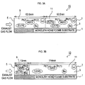
- the slurry S7 is applied to coat an internal surface of the through hole 3 of the substrate 1 over a range of 13 mm from the entrance end 5 (an area A) and is dried. Then, calcination is performed at a temperature of 350°C or higher for an hour. In this process, a catalyst coating layer (an upstream side catalyst coating layer 9) is formed on the internal surface of the through hole 3 over a range of 13 mm from the entrance end 5 (see FIG. 3B).
- the slurry S8 is applied to coat an internal surface of the through hole 3 of the substrate 1 over a range of 114 mm from the exit end 7 (an area B) and is dried. Then, calcination is performed at a temperature of 350°C or higher for an hour. In this process, a catalyst coating layer (a downstream side catalyst coating layer 11) is formed on the internal surface of the through hole 3 over a range of 114 mm from the exit end 7, and thus an exhaust gas purifying catalyst 13 is produced as shown in FIG. 3B.
- Embodiment 7 Although an exhaust gas purifying catalyst 13 in Embodiment 7 is produced basically in the same manner as in Embodiment 1, there are some differences. Accordingly, a description will now be made mainly with respect to the differences.
- Embodiment 7 a carrier powder H6 as described below is prepared in place of the carrier powder H1. (Carrier powder H6)
- each of the amounts of Pt and Rh contained in the upstream side catalyst coating layer 9 is changed to 2.7 g, and each of the amounts of Pt and Rh contained in the downstream side catalyst coating layer 11 is changed to 0.3 g in Embodiment 7, as shown in FIG. 4.
- Embodiment 8 Although an exhaust gas purifying catalyst 13 in Embodiment 8 is produced basically in the same manner as in Embodiment 1, there are some differences. Accordingly, a description will now be made mainly with respect to the differences.
- the upstream side catalyst coating layer 9 is formed on an internal surface of the through hole 3 over a range of 77 mm from the entrance end 5 (see FIG. 5A).
- the downstream side catalyst coating layer 11 is formed on an internal surface of the through hole 3 over a range of 50 mm from the exit end 7.
- Embodiment 9 Although an exhaust gas purifying catalyst 13 in Embodiment 9 is produced basically in the same manner as in Embodiment 1, there are some differences. Accordingly, a description will now be made mainly with respect to the differences.
- each of the amounts of Pt and Rh contained in the upstream side catalyst coating layer 9 is changed to 1.5 g, and each of the amounts of Pt and Rh contained in the downstream side catalyst coating layer 11 is changed to 1.5 g in Embodiment 9, as shown in FIG. 5B.
- the ZrCe mixed oxide (The oxide equivalent weight of Zr is 70 wt% of the oxide equivalent weight of Zr and Ce contained in the ZrCe mixed oxide.) contained in the slurry S1 in Embodiment 1 is replaced by the ZrCe mixed oxide (The oxide equivalent weight of Zr is 50 wt% of the oxide equivalent weight of Zr and Ce contained in the ZrCe mixed oxide.) in Comparative Example 1.
- the ZrCe mixed oxide (The oxide equivalent weight of Zr is 50 wt% of the oxide equivalent weight of Zr and Ce contained in the ZrCe mixed oxide.) is included in the upstream side catalyst coating layer 9, as shown in FIG. 6A.
- the ZrCe mixed oxide (The oxide equivalent weight of Ce is 50 wt% of the oxide equivalent weight of Zr and Ce contained in the ZrCe mixed oxide.) contained in the slurry S2 in Embodiment 1 is replaced by the ZrCe mixed oxide (The oxide equivalent weight of Ce is 30 wt% of the oxide equivalent weight of Zr and Ce contained in the ZrCe mixed oxide.) in Comparative Example 2.
- the ZrCe mixed oxide (The oxide equivalent weight of Ce is 30 wt% of the oxide equivalent weight of Zr and Ce contained in the ZrCe mixed oxide.) is included in the downstream side catalyst coating layer 11, as shown in FIG. 6B.
- the substrate 1 used in Comparative Example 3 is the same as in Embodiments 1 through 9 and Comparative Examples 1 and 2.
- the slurry S15 is applied to coat an entire internal surface of the through hole 3 of the substrate 1 (over a range from the entrance end 5 to the exit end 7) and is dried. Then, calcination is performed at a temperature of 350°C or higher for an hour. In this process, a uniform catalyst coating layer is formed over the entire internal surface of the through hole 3 (see FIG. 7).
- the exhaust gas purifying catalysts 13 according to Embodiments 1 through 9 respectively provide high Bag1HC purification rates (%) and reduce the total emission.
- the length of the upstream catalyst coating layer 9 is within a range of 10% to 50 % of the total length of the through hole 3. Accordingly, these exhaust gas purifying catalysts 13 are superior in terms of the Bag1HC purification rate (%) and the total emission (especially NMHC and NOx) compared with Embodiment 8 in which the length is beyond the above range.
- the proportions between the weight of the precious metal contained in the upstream catalyst coating layer 9 and the weight of the precious metal contained in the downstream catalyst coating layer 11 are within a range from 2:1 to 10:1. Accordingly, these exhaust gas purifying catalysts 13 are superior in terms of the Bag1HC purification rate (%) and the total emission (especially NMHC) as compared with Embodiment 9 in which the length is beyond the above range.
- the oxide equivalent content of Zr contained in the upstream catalyst coating layer 9 is 50 wt% of the oxide equivalent weight of Zr and Ce contained in the ZrCe mixed oxide, i.e., beyond a range of 51-100 wt%. Accordingly, the exhaust gas purifying catalyst 13 of Comparative Example 1 is inferior in terms of the Bag1HC purification rate (%) and the total emission (especially NMHC).
- the oxide equivalent content of Ce contained in the downstream catalyst coating layer 11 is 30 wt% of the oxide equivalent weight of Zr and Ce contained in the ZrCe mixed oxide, i.e., beyond a range of 58-100 wt%. Accordingly, the exhaust gas purifying catalyst 13 of Comparative Example 2 is inferior in terms of the Bag1HC purification rate (%) and the total emission (especially NOx).
- Comparative Example 3 the coating layer is not divided into the upstream catalyst coating layer 9 and the downstream catalyst coating layer 11. Accordingly, the exhaust gas purifying catalyst 13 of Comparative Example 3 is inferior in terms of the Bag1HC purification rate (%) and the total emission (NMHC, CO and NOx).
- the precious metal carried by the upstream catalyst coating layer 9 or the downstream catalyst coating layer 11 in Embodiments 1 through 9 may be a combination of Pd and Rh, or may be a single type of precious metal. It has been confirmed that the same effects are shown in the same experiments in these cases.
- the exhaust gas purifying catalysts 13 according to Embodiments 1 through 9 may be produced by coating the substrate 1 with a refractory inorganic oxide (alumina, Zr oxide, Ce oxide, Zr Ce mixed oxide) and subsequently soaking the coated substrate 1 in a slurry containing a precious metal (Pt, Rh).
- a refractory inorganic oxide alumina, Zr oxide, Ce oxide, Zr Ce mixed oxide
Landscapes
- Chemical & Material Sciences (AREA)
- Engineering & Computer Science (AREA)
- Chemical Kinetics & Catalysis (AREA)
- Materials Engineering (AREA)
- Organic Chemistry (AREA)
- Health & Medical Sciences (AREA)
- Combustion & Propulsion (AREA)
- Biomedical Technology (AREA)
- Environmental & Geological Engineering (AREA)
- Analytical Chemistry (AREA)
- General Chemical & Material Sciences (AREA)
- Oil, Petroleum & Natural Gas (AREA)
- Catalysts (AREA)
- Exhaust Gas Treatment By Means Of Catalyst (AREA)
Applications Claiming Priority (1)
| Application Number | Priority Date | Filing Date | Title |
|---|---|---|---|
| JP2004377850A JP4768260B2 (ja) | 2004-12-27 | 2004-12-27 | 排ガス浄化用触媒 |
Publications (2)
| Publication Number | Publication Date |
|---|---|
| EP1674148A2 true EP1674148A2 (de) | 2006-06-28 |
| EP1674148A3 EP1674148A3 (de) | 2009-03-04 |
Family
ID=36117652
Family Applications (1)
| Application Number | Title | Priority Date | Filing Date |
|---|---|---|---|
| EP05028154A Withdrawn EP1674148A3 (de) | 2004-12-27 | 2005-12-22 | Abgasreinigungskatalysator |
Country Status (3)
| Country | Link |
|---|---|
| US (2) | US7846863B2 (de) |
| EP (1) | EP1674148A3 (de) |
| JP (1) | JP4768260B2 (de) |
Cited By (2)
| Publication number | Priority date | Publication date | Assignee | Title |
|---|---|---|---|---|
| EP2014360A1 (de) * | 2007-07-11 | 2009-01-14 | Peugeot Citroen Automobiles SA | Vorrichtung zur Behandlung der gasförmigen Emissionen aus einem Motor |
| WO2011077139A1 (en) * | 2009-12-21 | 2011-06-30 | Johnson Matthey Plc | NOx TRAP |
Families Citing this family (19)
| Publication number | Priority date | Publication date | Assignee | Title |
|---|---|---|---|---|
| JP4760625B2 (ja) * | 2006-09-06 | 2011-08-31 | マツダ株式会社 | 排ガス浄化用触媒装置 |
| JP4787704B2 (ja) * | 2006-09-15 | 2011-10-05 | 第一稀元素化学工業株式会社 | 自動車用排気ガス浄化装置に用いられる触媒系、それを用いた排気ガス浄化装置、及び排気ガス浄化方法 |
| EP2318673B1 (de) * | 2008-02-05 | 2019-09-18 | BASF Corporation | Partikelfilter aufweisende systeme zur behandlung von benzinmotoremissionen |
| JP2009255033A (ja) * | 2008-03-27 | 2009-11-05 | Ibiden Co Ltd | ハニカム構造体および排ガス処理装置 |
| US7981390B2 (en) * | 2008-12-23 | 2011-07-19 | Basf Corporation | Small engine palladium catalyst article and method of making |
| JP2012035206A (ja) * | 2010-08-09 | 2012-02-23 | Johnson Matthey Japan Inc | 排ガス浄化触媒 |
| JP5240275B2 (ja) * | 2010-10-22 | 2013-07-17 | トヨタ自動車株式会社 | 排ガス浄化用触媒 |
| JP2015112553A (ja) * | 2013-12-12 | 2015-06-22 | 株式会社キャタラー | 排気ガス浄化用触媒 |
| EP3501648B1 (de) | 2017-12-19 | 2023-10-04 | Umicore Ag & Co. Kg | Katalytisch aktives partikelfilter |
| EP3505245B1 (de) | 2017-12-19 | 2019-10-23 | Umicore Ag & Co. Kg | Katalytisch aktives partikelfilter |
| EP3505246B1 (de) | 2017-12-19 | 2019-10-23 | Umicore Ag & Co. Kg | Katalytisch aktives partikelfilter |
| WO2019187199A1 (ja) * | 2018-03-28 | 2019-10-03 | 三井金属鉱業株式会社 | 排ガス浄化用触媒 |
| CN113646064A (zh) | 2019-03-29 | 2021-11-12 | 优美科股份公司及两合公司 | 催化活性微粒过滤器 |
| JP7288331B2 (ja) * | 2019-03-29 | 2023-06-07 | 株式会社キャタラー | 排ガス浄化触媒装置 |
| JP7372052B2 (ja) * | 2019-05-15 | 2023-10-31 | 株式会社キャタラー | 排ガス浄化触媒装置 |
| JP6980061B1 (ja) | 2020-06-26 | 2021-12-15 | 株式会社キャタラー | 排ガス浄化用触媒 |
| JP7317787B2 (ja) * | 2020-10-19 | 2023-07-31 | トヨタ自動車株式会社 | 排ガス浄化装置 |
| US11788450B2 (en) * | 2020-10-30 | 2023-10-17 | Johnson Matthey Public Limited Company | TWC catalysts for gasoline engine exhaust gas treatments |
| WO2022090689A1 (en) | 2020-10-30 | 2022-05-05 | Johnson Matthey Public Limited Company | Novel tri-metal pgm catalysts for gasoline engine exhaust gas treatments |
Citations (3)
| Publication number | Priority date | Publication date | Assignee | Title |
|---|---|---|---|---|
| JPH03196841A (ja) | 1989-12-26 | 1991-08-28 | Nok Corp | 排気ガス浄化用触媒 |
| JPH0523593A (ja) | 1991-07-22 | 1993-02-02 | Nippon Shokubai Co Ltd | 排気ガス浄化システム |
| JP2001259424A (ja) | 2000-03-22 | 2001-09-25 | Cataler Corp | 排気ガス浄化用触媒 |
Family Cites Families (10)
| Publication number | Priority date | Publication date | Assignee | Title |
|---|---|---|---|---|
| JPH0549940A (ja) * | 1991-08-13 | 1993-03-02 | Nippon Shokubai Co Ltd | 排気ガス浄化システム |
| CA2064977C (en) | 1991-04-05 | 1998-09-22 | Eiichi Shiraishi | Catalyst for purifying exhaust gas |
| DE69435061T2 (de) * | 1993-06-25 | 2008-12-18 | Basf Catalysts Llc | Katalysatorzusammensetzung |
| EP0664147B1 (de) * | 1994-01-20 | 1998-07-22 | Toyota Jidosha Kabushiki Kaisha | Katalysator zur Reinigung von Abgasen |
| US6497851B1 (en) * | 1994-12-06 | 2002-12-24 | Englehard Corporation | Engine exhaust treatment apparatus and method of use |
| JP4029233B2 (ja) * | 1998-05-11 | 2008-01-09 | 第一稀元素化学工業株式会社 | セリウム−ジルコニウム系複合酸化物及びその製造方法ならびに排ガス浄化用触媒材料 |
| JP3196841B2 (ja) | 1998-11-18 | 2001-08-06 | 日本電気株式会社 | 異方性薄膜評価方法、評価装置及び記録媒体 |
| JP4459346B2 (ja) * | 1999-12-09 | 2010-04-28 | 株式会社キャタラー | 排ガス浄化用触媒 |
| US6846466B2 (en) * | 2000-03-22 | 2005-01-25 | Cataler Corporation | Catalyst for purifying an exhaust gas |
| JP3855266B2 (ja) * | 2001-11-01 | 2006-12-06 | 日産自動車株式会社 | 排気ガス浄化用触媒 |
-
2004
- 2004-12-27 JP JP2004377850A patent/JP4768260B2/ja not_active Expired - Lifetime
-
2005
- 2005-12-22 EP EP05028154A patent/EP1674148A3/de not_active Withdrawn
- 2005-12-23 US US11/318,190 patent/US7846863B2/en active Active
-
2010
- 2010-11-15 US US12/946,283 patent/US20110082032A1/en not_active Abandoned
Patent Citations (3)
| Publication number | Priority date | Publication date | Assignee | Title |
|---|---|---|---|---|
| JPH03196841A (ja) | 1989-12-26 | 1991-08-28 | Nok Corp | 排気ガス浄化用触媒 |
| JPH0523593A (ja) | 1991-07-22 | 1993-02-02 | Nippon Shokubai Co Ltd | 排気ガス浄化システム |
| JP2001259424A (ja) | 2000-03-22 | 2001-09-25 | Cataler Corp | 排気ガス浄化用触媒 |
Cited By (7)
| Publication number | Priority date | Publication date | Assignee | Title |
|---|---|---|---|---|
| EP2014360A1 (de) * | 2007-07-11 | 2009-01-14 | Peugeot Citroen Automobiles SA | Vorrichtung zur Behandlung der gasförmigen Emissionen aus einem Motor |
| FR2918706A1 (fr) * | 2007-07-11 | 2009-01-16 | Peugeot Citroen Automobiles Sa | Dispositif de traitement des emissions gazeuses d'un moteur. |
| WO2011077139A1 (en) * | 2009-12-21 | 2011-06-30 | Johnson Matthey Plc | NOx TRAP |
| CN102740953A (zh) * | 2009-12-21 | 2012-10-17 | 约翰逊马西有限公司 | NOx捕集器 |
| GB2476573B (en) * | 2009-12-21 | 2014-04-09 | Johnson Matthey Plc | NOx trap |
| RU2554576C2 (ru) * | 2009-12-21 | 2015-06-27 | Джонсон Мэттей Плк | Катализатор оксидов азота накопительного типа |
| CN102740953B (zh) * | 2009-12-21 | 2015-11-25 | 约翰逊马西有限公司 | NOx捕集器 |
Also Published As
| Publication number | Publication date |
|---|---|
| US7846863B2 (en) | 2010-12-07 |
| JP2006181476A (ja) | 2006-07-13 |
| EP1674148A3 (de) | 2009-03-04 |
| JP4768260B2 (ja) | 2011-09-07 |
| US20110082032A1 (en) | 2011-04-07 |
| US20060142151A1 (en) | 2006-06-29 |
Similar Documents
| Publication | Publication Date | Title |
|---|---|---|
| US20110082032A1 (en) | Exhasut gas purifying catalyst | |
| US7842643B2 (en) | Exhaust gas purifying catalyst | |
| US8168560B2 (en) | Exhaust gas purifying catalyst | |
| KR100719074B1 (ko) | 배기가스 정화용 촉매 및 배기가스의 정화 방법 | |
| US7998896B2 (en) | Exhaust gas purifying catalyst | |
| KR101059807B1 (ko) | 배기가스 정화용 촉매 | |
| EP2025401B1 (de) | Nox-reduktionskatalysator, nox-reduktionskatalysatorsystem und verfahren zur reduktion von nox | |
| US6921738B2 (en) | Catalytic metal plate | |
| EP1146952B1 (de) | Abgasreinigungskatalysator | |
| EP1916031B1 (de) | Abgasreinigungskatalysator | |
| EP2036603A1 (de) | Abgasreinigungskatalysator | |
| US8071502B2 (en) | Exhaust gas purifying catalyst | |
| EP3632537A1 (de) | Katalysatorvorrichtung zur abgasreinigung | |
| EP4241880A1 (de) | Katalysatorvorrichtung zur abgasreinigung | |
| EP2692436B1 (de) | Abgasreinigungskatalysator | |
| US10408102B2 (en) | Oxidation catalyst device for exhaust gas purification | |
| EP1570903B1 (de) | ABGASREINIGUNGS-KATALYSATOR, VERFAHREN ZUR REINIGUNG VON ABGAS und Verwendung einer Katalysatorkomponente zur Unterdrückung der Oxidation von Schwefeldioxid in Abgasen | |
| US7795174B2 (en) | Catalyst for purifying exhaust gases | |
| CN104005821A (zh) | 废气用催化装置 | |
| EP0951340B1 (de) | Katalytische metallplatte | |
| KR100879965B1 (ko) | 배기가스정화용 촉매 | |
| JP4716087B2 (ja) | 排ガス浄化用触媒 | |
| US20260021449A1 (en) | Selective catalytic reduction system for exhaust gas treatment, and exhaust gas purification apparatus for lean combustion engines comprising selective catalytic reduction system for exhaust gas treatment | |
| EP2145672A2 (de) | NOx-Speicherkatalysator | |
| CN121729281A (zh) | 废气净化催化剂 |
Legal Events
| Date | Code | Title | Description |
|---|---|---|---|
| PUAI | Public reference made under article 153(3) epc to a published international application that has entered the european phase |
Free format text: ORIGINAL CODE: 0009012 |
|
| AK | Designated contracting states |
Kind code of ref document: A2 Designated state(s): AT BE BG CH CY CZ DE DK EE ES FI FR GB GR HU IE IS IT LI LT LU LV MC NL PL PT RO SE SI SK TR |
|
| AX | Request for extension of the european patent |
Extension state: AL BA HR MK YU |
|
| PUAL | Search report despatched |
Free format text: ORIGINAL CODE: 0009013 |
|
| AK | Designated contracting states |
Kind code of ref document: A3 Designated state(s): AT BE BG CH CY CZ DE DK EE ES FI FR GB GR HU IE IS IT LI LT LU LV MC NL PL PT RO SE SI SK TR |
|
| AX | Request for extension of the european patent |
Extension state: AL BA HR MK YU |
|
| 17Q | First examination report despatched |
Effective date: 20090916 |
|
| 17P | Request for examination filed |
Effective date: 20090826 |
|
| AKX | Designation fees paid |
Designated state(s): AT BE BG CH CY CZ DE DK EE ES FI FR GB GR HU IE IS IT LI LT LU LV MC NL PL PT RO SE SI SK TR |
|
| STAA | Information on the status of an ep patent application or granted ep patent |
Free format text: STATUS: EXAMINATION IS IN PROGRESS |
|
| STAA | Information on the status of an ep patent application or granted ep patent |
Free format text: STATUS: THE APPLICATION IS DEEMED TO BE WITHDRAWN |
|
| 18D | Application deemed to be withdrawn |
Effective date: 20180703 |