EP1674679A2 - Moteur à combustion avec dispositif d'air frais et de ventilation - Google Patents
Moteur à combustion avec dispositif d'air frais et de ventilation Download PDFInfo
- Publication number
- EP1674679A2 EP1674679A2 EP05109490A EP05109490A EP1674679A2 EP 1674679 A2 EP1674679 A2 EP 1674679A2 EP 05109490 A EP05109490 A EP 05109490A EP 05109490 A EP05109490 A EP 05109490A EP 1674679 A2 EP1674679 A2 EP 1674679A2
- Authority
- EP
- European Patent Office
- Prior art keywords
- combustion engine
- fresh air
- internal combustion
- nozzle
- hose
- Prior art date
- Legal status (The legal status is an assumption and is not a legal conclusion. Google has not performed a legal analysis and makes no representation as to the accuracy of the status listed.)
- Granted
Links
Images


Classifications
-
- F—MECHANICAL ENGINEERING; LIGHTING; HEATING; WEAPONS; BLASTING
- F02—COMBUSTION ENGINES; HOT-GAS OR COMBUSTION-PRODUCT ENGINE PLANTS
- F02M—SUPPLYING COMBUSTION ENGINES IN GENERAL WITH COMBUSTIBLE MIXTURES OR CONSTITUENTS THEREOF
- F02M25/00—Engine-pertinent apparatus for adding non-fuel substances or small quantities of secondary fuel to combustion-air, main fuel or fuel-air mixture
- F02M25/06—Engine-pertinent apparatus for adding non-fuel substances or small quantities of secondary fuel to combustion-air, main fuel or fuel-air mixture adding lubricant vapours
-
- F—MECHANICAL ENGINEERING; LIGHTING; HEATING; WEAPONS; BLASTING
- F01—MACHINES OR ENGINES IN GENERAL; ENGINE PLANTS IN GENERAL; STEAM ENGINES
- F01M—LUBRICATING OF MACHINES OR ENGINES IN GENERAL; LUBRICATING INTERNAL COMBUSTION ENGINES; CRANKCASE VENTILATING
- F01M13/00—Crankcase ventilating or breathing
-
- F—MECHANICAL ENGINEERING; LIGHTING; HEATING; WEAPONS; BLASTING
- F02—COMBUSTION ENGINES; HOT-GAS OR COMBUSTION-PRODUCT ENGINE PLANTS
- F02M—SUPPLYING COMBUSTION ENGINES IN GENERAL WITH COMBUSTIBLE MIXTURES OR CONSTITUENTS THEREOF
- F02M35/00—Combustion-air cleaners, air intakes, intake silencers, or induction systems specially adapted for, or arranged on, internal-combustion engines
- F02M35/10—Air intakes; Induction systems
- F02M35/10091—Air intakes; Induction systems characterised by details of intake ducts: shapes; connections; arrangements
- F02M35/10144—Connections of intake ducts to each other or to another device
-
- F—MECHANICAL ENGINEERING; LIGHTING; HEATING; WEAPONS; BLASTING
- F02—COMBUSTION ENGINES; HOT-GAS OR COMBUSTION-PRODUCT ENGINE PLANTS
- F02M—SUPPLYING COMBUSTION ENGINES IN GENERAL WITH COMBUSTIBLE MIXTURES OR CONSTITUENTS THEREOF
- F02M35/00—Combustion-air cleaners, air intakes, intake silencers, or induction systems specially adapted for, or arranged on, internal-combustion engines
- F02M35/10—Air intakes; Induction systems
- F02M35/10209—Fluid connections to the air intake system; their arrangement of pipes, valves or the like
- F02M35/10222—Exhaust gas recirculation [EGR]; Positive crankcase ventilation [PCV]; Additional air admission, lubricant or fuel vapour admission
-
- F—MECHANICAL ENGINEERING; LIGHTING; HEATING; WEAPONS; BLASTING
- F16—ENGINEERING ELEMENTS AND UNITS; GENERAL MEASURES FOR PRODUCING AND MAINTAINING EFFECTIVE FUNCTIONING OF MACHINES OR INSTALLATIONS; THERMAL INSULATION IN GENERAL
- F16L—PIPES; JOINTS OR FITTINGS FOR PIPES; SUPPORTS FOR PIPES, CABLES OR PROTECTIVE TUBING; MEANS FOR THERMAL INSULATION IN GENERAL
- F16L33/00—Arrangements for connecting hoses to rigid members; Rigid hose-connectors, i.e. single members engaging both hoses
- F16L33/22—Arrangements for connecting hoses to rigid members; Rigid hose-connectors, i.e. single members engaging both hoses with means not mentioned in the preceding groups for gripping the hose between inner and outer parts
- F16L33/227—Arrangements for connecting hoses to rigid members; Rigid hose-connectors, i.e. single members engaging both hoses with means not mentioned in the preceding groups for gripping the hose between inner and outer parts the hose being introduced into or onto the connecting member and automatically locked
-
- F—MECHANICAL ENGINEERING; LIGHTING; HEATING; WEAPONS; BLASTING
- F02—COMBUSTION ENGINES; HOT-GAS OR COMBUSTION-PRODUCT ENGINE PLANTS
- F02M—SUPPLYING COMBUSTION ENGINES IN GENERAL WITH COMBUSTIBLE MIXTURES OR CONSTITUENTS THEREOF
- F02M35/00—Combustion-air cleaners, air intakes, intake silencers, or induction systems specially adapted for, or arranged on, internal-combustion engines
- F02M35/10—Air intakes; Induction systems
- F02M35/10314—Materials for intake systems
- F02M35/10321—Plastics; Composites; Rubbers
-
- Y—GENERAL TAGGING OF NEW TECHNOLOGICAL DEVELOPMENTS; GENERAL TAGGING OF CROSS-SECTIONAL TECHNOLOGIES SPANNING OVER SEVERAL SECTIONS OF THE IPC; TECHNICAL SUBJECTS COVERED BY FORMER USPC CROSS-REFERENCE ART COLLECTIONS [XRACs] AND DIGESTS
- Y02—TECHNOLOGIES OR APPLICATIONS FOR MITIGATION OR ADAPTATION AGAINST CLIMATE CHANGE
- Y02T—CLIMATE CHANGE MITIGATION TECHNOLOGIES RELATED TO TRANSPORTATION
- Y02T10/00—Road transport of goods or passengers
- Y02T10/10—Internal combustion engine [ICE] based vehicles
- Y02T10/12—Improving ICE efficiencies
Definitions
- the present invention relates to an internal combustion engine, in particular for a motor vehicle, with the features of the preamble of claim 1.
- the invention also relates to a fresh air system and a venting device for such an internal combustion engine.
- a modern internal combustion engine is equipped with a fresh air system for supplying the internal combustion engine with fresh air and with a venting device for discharging blow-by gases from the internal combustion engine.
- blow-by gases pass into a crankcase of the internal combustion engine due to unavoidable leaks between piston and cylinder. So that the crankcase no unacceptably high pressure, the blow-by gases are removed by means of the venting device.
- the blow-by gases with the help of the venting device are appropriate supplied to the fresh air system, that is, the blow-by gases are again supplied to the combustion of the internal combustion engine.
- a hose of the venting device is connected via a connecting piece to a line of the fresh air system.
- hose For the installation of the internal combustion engine said hose must be connected to the nozzle of the pipe. This connection process should be feasible with one hand to save assembly time. In addition, the hose must be able to be removed again from the nozzle nondestructively, for example, to be able to carry out repairs.
- a connector known, on the one hand has a hose connection and on the other hand, a nozzle connection.
- the hose connection is barb-like and has a circumferential annular groove in which a sealing ring is arranged.
- An outlet section of the hose can be attached to this hose connection in order to connect it firmly and permanently to the connector.
- the outlet section of the hose is "shot" onto the hose connection of the connector, this means that the hose is heated at least in its outlet section and subsequently plugged onto the hose connection, wherein the outlet section can be easily elastically expanded due to the elevated temperature.
- connection between hose and connector has a high pull-out strength and is not intended for a detachable removal of the hose from the connector.
- the nozzle connection of the connector is provided with a releasable catch, which automatically engages when connecting the nozzle connection to the nozzle on the nozzle.
- the locking is achieved in a suitable manner, so that the nozzle connection can be removed from the nozzle nondestructive.
- the nozzle connection further sealing rings are arranged, which cooperate in the assembled state with the inserted nozzle.
- the hose of the venting device can be easily connected via the nozzle to the line of the fresh air system.
- the disassembly is easy and non-destructive realizable.
- the disadvantage, however, is that such a connector is relatively expensive.
- the present invention is concerned with the problem of pointing for the connection of the hose of the venting device via the pipe to the line of the fresh air system a cheap way.
- the invention is based on the general idea to place the hose with its outlet section directly on the inlet section of the nozzle and to provide at least one window-like side opening in the outlet section for securing, in which engages a barb formed on the inlet section.
- side openings in the outlet section of the hose can be produced inexpensively.
- barbs can be formed inexpensively at the inlet portion of the nozzle. The price advantage resulting from the invention is obvious.
- the hose is expediently designed, at least in its outlet section, for example by shaping and / or material selection, such that it reversibly deforms when being attached to the inlet section of the connecting piece.
- the at least one side opening in the circumferential direction of the outlet section may be designed as a slot, which may preferably extend over 30 ° to 45 °.
- a slot By the execution of at least one side opening as a slot, can be the hose mounted in different rotational positions on the neck, if then the at least one barb in the circumferential direction is dimensioned correspondingly smaller than the respective side opening. This measure simplifies the assembly, since manufacturing tolerances can be compensated.
- an internal combustion engine 1 in particular for a motor vehicle, is equipped with a fresh air system 2, with a ventilation device 3 and expediently with an exhaust system 4.
- the fresh air system 2 is used to supply the internal combustion engine 1 with fresh air and comprises at least one line 5.
- the fresh air system 2 can in the usual manner further, not shown here components, such as. a fresh air filter included.
- the venting device 3 is used for discharging blow-by gases from the internal combustion engine 1.
- the venting device 3 is connected at one end to an engine block 6 of the internal combustion engine 1 and communicates there with a crankcase.
- the venting device 3 a hose 7, which is connected via a connecting piece 8 to the line 5.
- the symbolized by arrows blow-by gases 9 can in this way also by Arrows symbolized fresh air 10 are supplied.
- the venting device 3 can in the usual way more, not shown here components such. B. a droplet, have.
- the exhaust system 4 is used for discharging indicated by an arrow combustion exhaust gases 11 from the internal combustion engine 1.
- the exhaust system 4 can also other components, not shown here, such. Silencer, catalytic converter, particulate filter exhibit.
- the line 5 of the fresh air system 2 is equipped with the nozzle 8.
- the nozzle 8 can - as here - be sprayed onto the line 5.
- the nozzle 8 consists of a suitable plastic.
- the line 5 is made of a plastic. It is also possible to form the spigot 8 integrally on the conduit 5, that is, spigot 8 and conduit 5 are simultaneously formed in a tool, e.g. injection molded.
- a heating device suitable for this purpose may be provided, which, however, is not shown here.
- the nozzle 8 may also be a separately manufactured component which may be attached to the conduit 5 in any suitable manner.
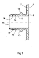
- the nozzle 8 has an inlet portion 12 which is cylindrical or sleeve-shaped. At this inlet section 12, the connecting piece 8 has at least one laterally projecting barb 13. In the example shown, two such barbs 13 are provided, which are arranged diametrically opposite one another. The number of barbs 13 is basically arbitrary.
- the nozzle 8 is equipped at its inlet section 12 with at least one annular groove 14.
- two such annular grooves 14 are provided by way of example, each of which circulates closed on the outside at the inlet section 12.
- these annular grooves 14 each have a sealing ring 15 is inserted, preferably an O-ring.
- the annular grooves 14 and thus the sealing rings 15 are positioned between the barbs 13 and an inlet end 16 of the inlet section 12 and the connecting piece 8.
- the nozzle 8 is also chamfered here at its inlet end 16.
- the hose 7 has an outlet section 17, which is expediently cylindrically shaped.
- the hose 7 has at least one side opening 18 at its outlet section 17.
- two such side openings 18 are provided by way of example, which are diametrically opposed to one another. Appropriately agrees the number and arrangement of the barbs 13 with the number and arrangement of the side openings 18 match.
- the side openings 18 are characterized by a circumferentially closed edge 19, that is, the side openings 18 are each completely enclosed by the material of the outlet portion 17.
- the side openings 18 are dimensioned such that they each form a slot in the circumferential direction of the outlet section 17. Accordingly, the side openings 18 are sized larger in the circumferential direction of the exit portion 17 than in the axial direction of the peripheral portion 17. Preferably, the side openings 18 in the circumferential direction of the exit portion 17 each extend in a range of about 30 ° to 45 °.
- the tube 7 can subsequently have, at its outlet section 17, a section 20 which can be designed as a corrugated tube and thus has a certain flexibility.
- the tube 7 can be connected to the line 5, that the outlet portion 17 of the tube 7 is attached to the inlet portion 12 of the nozzle 8, such that each barb 13 engages in the associated side opening 18.
- the tube 7 is thereby secured to the nozzle 8.
- a gas-tight connection between the tube 7 and nozzle 8 is ensured by the seals 15.
- the hose 7 is like the nozzle 8 expediently made of plastic.
- the design of the tube 7, at least in the outlet section 17, preferably takes place in such a way that the outlet section 17 only deforms reversibly when it is plugged onto the inlet section 8, so that the barbs 13 in the side openings 18 in each case effectively engage behind an edge section 21 which extends from the side respective side opening 18 extends to the outlet end 22 of the tube 7.
- This reversible deformability of the outlet section 17 can be realized by a suitable dimensioning of the outlet section 17.
- the wall thickness of the outlet section 17 can accordingly be smaller than that of the inlet section 12.
- the deformability of the outlet section 17 can also be achieved or at least supported by a suitable material selection.
- the plastic of the tube 7 and the outlet portion 17 is preferably softer than the plastic of the nozzle 8. As a result, the outlet portion 17 yield during insertion and expand, while the stiffer nozzle 8 remains substantially dimensionally stable.
- the shape of the barbs 13 is suitably chosen so that they facilitate the expansion of the outlet portion 17 at least in the edge region 21 when plugging.
- the barbs 13 thus form an inclined ramp in the slip-on.
- the barbs 13 are also shaped so that they take off the hose 7 from Stutzen 8 complicate or prevent.
- the barbs 13 in the extension direction form a step which protrudes substantially radially.
- the engagement in the side opening 18 is characterized in terms of the achieved positive connection particularly effective.
- the barbs 13 in the circumferential direction of the inlet section 12 and the outlet section 17 are dimensioned smaller than the side openings 18. In this way, the rotational position between outlet section 17 and inlet section 12 can be changed, since the barbs 13 in the circumferential direction within the side openings 18 are adjustable.
- the connection of the tube 7 to the line 5 is considerably simplified since tolerance-related deviations between the rotational position of the outlet portion 17 relative to the inlet portion 12 can be compensated by the dimensioning of the slot-like side openings 18.
- the tube 7 For dismantling the tube 7, it can be suitably rotated in the circumferential direction, such that the barbs 13 displace the peripheral area delimiting the lateral openings 18 radially outward. Once the barbs 13 are unscrewed from the side openings 18, the hose 7 can be deducted from the nozzle 8.
- the barbs 13 in the circumferential direction at least on one side, for. Clockwise and / or counterclockwise, also have a ramp, which simplify the driving under and radial displacement of the outlet section 17 in the respective edge region of the side openings 18.
Landscapes
- Engineering & Computer Science (AREA)
- General Engineering & Computer Science (AREA)
- Mechanical Engineering (AREA)
- Chemical & Material Sciences (AREA)
- Combustion & Propulsion (AREA)
- Lubrication Details And Ventilation Of Internal Combustion Engines (AREA)
Applications Claiming Priority (1)
| Application Number | Priority Date | Filing Date | Title |
|---|---|---|---|
| DE102004063459A DE102004063459A1 (de) | 2004-12-23 | 2004-12-23 | Brennkraftmaschine mit Frischluftanlage und Entlüftungseinrichtung |
Publications (3)
| Publication Number | Publication Date |
|---|---|
| EP1674679A2 true EP1674679A2 (fr) | 2006-06-28 |
| EP1674679A3 EP1674679A3 (fr) | 2007-04-18 |
| EP1674679B1 EP1674679B1 (fr) | 2016-02-17 |
Family
ID=36072003
Family Applications (1)
| Application Number | Title | Priority Date | Filing Date |
|---|---|---|---|
| EP05109490.2A Expired - Lifetime EP1674679B1 (fr) | 2004-12-23 | 2005-10-12 | Moteur à combustion avec dispositif d'air frais et de ventilation |
Country Status (2)
| Country | Link |
|---|---|
| EP (1) | EP1674679B1 (fr) |
| DE (1) | DE102004063459A1 (fr) |
Cited By (10)
| Publication number | Priority date | Publication date | Assignee | Title |
|---|---|---|---|---|
| WO2011006584A3 (fr) * | 2009-07-16 | 2011-04-14 | Rheinmetall Landsysteme Gmbh | Raccordement de tuyau |
| WO2011120797A1 (fr) * | 2010-03-30 | 2011-10-06 | Mahle International Gmbh | Dispositif de raccordement, dispositif de dégazage de carter de vilebrequin et installation d'air frais |
| EP2407698A3 (fr) * | 2010-07-13 | 2013-08-21 | MAHLE International GmbH | Dispositif de couplage, dispositif d'aération du carter de vilebrequin et installation d'air frais |
| EP2837530A1 (fr) * | 2013-08-12 | 2015-02-18 | Continental Automotive GmbH | Capteur de choc doté d'un tuyau déformable élastiquement et capteur de pression et ouverture radiale dans le tuyau pour la fixation |
| CN107012924A (zh) * | 2017-05-31 | 2017-08-04 | 福建省天力卫浴科技有限公司 | 一种紧凑型水槽下水系统 |
| CN107869618A (zh) * | 2017-11-30 | 2018-04-03 | 西安交通大学 | 一种冰箱压缩机内排管连接结构 |
| WO2019104715A1 (fr) | 2017-12-01 | 2019-06-06 | Mann+Hummel Gmbh | Ensemble conduit de fluide et raccords pour un conduit de fluide |
| DE102019001812A1 (de) * | 2019-03-15 | 2020-09-17 | Volkswagen Aktiengesellschaft | Rohr-Schlauch-Anordnung |
| JP2021095877A (ja) * | 2019-12-17 | 2021-06-24 | 株式会社クボタ | エンジンの吸気装置 |
| IT202300004560A1 (it) * | 2023-03-10 | 2024-09-10 | Fca Italy Spa | “elemento tubolare sensorizzato di un sistema di alimentazione di aria di combustione e motore a combustione interna incorporante detto elemento tubolare” |
Families Citing this family (5)
| Publication number | Priority date | Publication date | Assignee | Title |
|---|---|---|---|---|
| DE102007017668A1 (de) | 2007-04-14 | 2008-10-16 | Bayerische Motoren Werke Aktiengesellschaft | Aufgeladene Brennkraftmaschine und Verfahren zur Überwachung, ob die Kurbelgehäuseentlüftung angeschlossen worden ist |
| DE102007056167A1 (de) * | 2007-11-21 | 2009-05-28 | Bombardier Transportation Gmbh | Verbindungsanordnung |
| DE102014211844A1 (de) | 2014-06-20 | 2015-12-24 | Contitech Mgw Gmbh | Kupplungselement zur flexiblen Verbindung zweier Elemente zur Führung von Medien |
| DE102017215896A1 (de) | 2017-09-08 | 2019-03-14 | Mahle International Gmbh | Schlauchverbindung mit Elastomerschlauch |
| DE102017221735A1 (de) | 2017-12-01 | 2019-06-06 | Volkswagen Aktiengesellschaft | Anordnung zum Ableiten von Blow-By-Gasen aus einem Kurbelgehäuse eines Verbrennungsmotors |
Family Cites Families (8)
| Publication number | Priority date | Publication date | Assignee | Title |
|---|---|---|---|---|
| DE1601384A1 (de) * | 1968-02-13 | 1970-11-05 | Hanomag Henschel Fahrzeug | Kurbelgehaeuseentlueftung von Motoren,insbesondere Dieselmotoren |
| DE3918785A1 (de) * | 1989-06-08 | 1990-12-13 | Bayerische Motoren Werke Ag | Sauganlage einer brennkraftmaschine |
| DE3932300C2 (de) * | 1989-09-28 | 2003-03-06 | Siemens Ag | Drosselklappenstutzen |
| GB2263956A (en) * | 1992-02-04 | 1993-08-11 | Ford Motor Co | A push-on pipe joint |
| FR2738035B1 (fr) * | 1995-08-25 | 1997-09-19 | Renault | Collecteur d'admission pour moteur a combustion interne |
| DE29818787U1 (de) * | 1998-10-22 | 1999-01-28 | Truplast Kunststofftechnik GmbH, 35428 Langgöns | Anordnung zum lösbaren Verbinden eines Schlauches mit einer Anschlußmuffe |
| DE19938189C2 (de) * | 1999-08-17 | 2002-11-28 | Kautex Textron Gmbh & Co Kg | Kühlmittelrohr für Brennkraftmaschinen sowie Verfahren zur Herstellung desselben |
| FR2831217B1 (fr) * | 2001-10-24 | 2004-04-09 | Wecosta | Filtre a air, conduit d'admission et ensemble constitue d'un filtre et d'un conduit d'admission de ce genre |
-
2004
- 2004-12-23 DE DE102004063459A patent/DE102004063459A1/de not_active Withdrawn
-
2005
- 2005-10-12 EP EP05109490.2A patent/EP1674679B1/fr not_active Expired - Lifetime
Cited By (14)
| Publication number | Priority date | Publication date | Assignee | Title |
|---|---|---|---|---|
| WO2011006584A3 (fr) * | 2009-07-16 | 2011-04-14 | Rheinmetall Landsysteme Gmbh | Raccordement de tuyau |
| CN106930870A (zh) * | 2010-03-30 | 2017-07-07 | 马勒国际有限公司 | 联接装置、曲轴箱通风装置和新风系统 |
| WO2011120797A1 (fr) * | 2010-03-30 | 2011-10-06 | Mahle International Gmbh | Dispositif de raccordement, dispositif de dégazage de carter de vilebrequin et installation d'air frais |
| CN102822458A (zh) * | 2010-03-30 | 2012-12-12 | 马勒国际有限公司 | 联接装置、曲轴箱通风装置和新风系统 |
| EP2407698A3 (fr) * | 2010-07-13 | 2013-08-21 | MAHLE International GmbH | Dispositif de couplage, dispositif d'aération du carter de vilebrequin et installation d'air frais |
| US8727382B2 (en) | 2010-07-13 | 2014-05-20 | Mahle International Gmbh | Coupling device, crankcase ventilation device and fresh air system |
| EP2837530A1 (fr) * | 2013-08-12 | 2015-02-18 | Continental Automotive GmbH | Capteur de choc doté d'un tuyau déformable élastiquement et capteur de pression et ouverture radiale dans le tuyau pour la fixation |
| CN107012924A (zh) * | 2017-05-31 | 2017-08-04 | 福建省天力卫浴科技有限公司 | 一种紧凑型水槽下水系统 |
| CN107869618A (zh) * | 2017-11-30 | 2018-04-03 | 西安交通大学 | 一种冰箱压缩机内排管连接结构 |
| WO2019104715A1 (fr) | 2017-12-01 | 2019-06-06 | Mann+Hummel Gmbh | Ensemble conduit de fluide et raccords pour un conduit de fluide |
| DE102019001812A1 (de) * | 2019-03-15 | 2020-09-17 | Volkswagen Aktiengesellschaft | Rohr-Schlauch-Anordnung |
| JP2021095877A (ja) * | 2019-12-17 | 2021-06-24 | 株式会社クボタ | エンジンの吸気装置 |
| IT202300004560A1 (it) * | 2023-03-10 | 2024-09-10 | Fca Italy Spa | “elemento tubolare sensorizzato di un sistema di alimentazione di aria di combustione e motore a combustione interna incorporante detto elemento tubolare” |
| WO2024189495A1 (fr) * | 2023-03-10 | 2024-09-19 | Stellantis Europe S.P.A. | Élément tubulaire instrumenté d'un système d'alimentation en air de combustion et moteur à combustion interne comprenant ledit élément tubulaire |
Also Published As
| Publication number | Publication date |
|---|---|
| EP1674679B1 (fr) | 2016-02-17 |
| EP1674679A3 (fr) | 2007-04-18 |
| DE102004063459A1 (de) | 2006-07-06 |
Similar Documents
| Publication | Publication Date | Title |
|---|---|---|
| EP1674679B1 (fr) | Moteur à combustion avec dispositif d'air frais et de ventilation | |
| EP1924801B1 (fr) | Systeme d'accouplement | |
| DE102008052552A1 (de) | Turbinengehäuse und Verfahren zu seiner Herstellung | |
| EP1953359A1 (fr) | Dispositif d'échappement d'un moteur à combustion interne | |
| EP1818533A2 (fr) | Système de sécurité pour un piège d'hydrocarbure | |
| EP3303816B1 (fr) | Silencieux de vehicule | |
| EP1451464A1 (fr) | Filtre a air d'admission pour un moteur a combustion interne | |
| DE102008046143A1 (de) | Schnellkupplungsanordnung | |
| EP2072103B1 (fr) | Cartouche de filtre et filtre à huile d'un moteur à combustion | |
| DE102019210078A1 (de) | Luftfiltermodul | |
| WO2009007165A1 (fr) | Tuyau d'air de charge | |
| EP2553224B1 (fr) | Dispositif de raccordement, dispositif de dégazage de carter de vilebrequin et installation d'air frais | |
| EP2639423B1 (fr) | Silencieux d'échappement | |
| EP2133615B1 (fr) | Dispositif de couplage, en particulier pour une installation d'air frais | |
| DE112007003066T5 (de) | Abgasrückführventil | |
| WO2012016614A1 (fr) | Dispositif de sécurité conçu pour un système de raccordement | |
| DE29922324U1 (de) | Flüssigkeitsfilter | |
| EP2616649B1 (fr) | Unité de traitement de gaz d'échappement, en particulier pour une conduite de recyclage de gaz d'échappement | |
| DE102014015613A1 (de) | Hohlfilterelement und Filter mit einem Hohlfilterelement | |
| EP2915973A1 (fr) | Agencement trémie-tube | |
| DE102004024465A1 (de) | Ansaugsystem | |
| EP1058782B1 (fr) | Dispositif d'admission pour moteur a combustion interne | |
| EP3798530B1 (fr) | Boitier d'évacuation du condensat d'un appareil de chauffage ainsi qu'appareil de chauffage doté d'un tel boitier | |
| EP1726794A1 (fr) | Silencieux d'échappement et procédé de fabrication | |
| DE102019118284A1 (de) | Dünnwandiges Bauteil mit Anschlusseinrichtung und Verfahren zu dessen Herstellung |
Legal Events
| Date | Code | Title | Description |
|---|---|---|---|
| PUAI | Public reference made under article 153(3) epc to a published international application that has entered the european phase |
Free format text: ORIGINAL CODE: 0009012 |
|
| AK | Designated contracting states |
Kind code of ref document: A2 Designated state(s): AT BE BG CH CY CZ DE DK EE ES FI FR GB GR HU IE IS IT LI LT LU LV MC NL PL PT RO SE SI SK TR |
|
| AX | Request for extension of the european patent |
Extension state: AL BA HR MK YU |
|
| PUAL | Search report despatched |
Free format text: ORIGINAL CODE: 0009013 |
|
| RIC1 | Information provided on ipc code assigned before grant |
Ipc: F02M 35/10 20060101ALN20070301BHEP Ipc: F01M 13/00 20060101AFI20060329BHEP Ipc: F16L 33/22 20060101ALI20070301BHEP Ipc: F16L 37/113 20060101ALI20070301BHEP Ipc: F02M 25/06 20060101ALI20070301BHEP |
|
| AK | Designated contracting states |
Kind code of ref document: A3 Designated state(s): AT BE BG CH CY CZ DE DK EE ES FI FR GB GR HU IE IS IT LI LT LU LV MC NL PL PT RO SE SI SK TR |
|
| AX | Request for extension of the european patent |
Extension state: AL BA HR MK YU |
|
| 17P | Request for examination filed |
Effective date: 20071006 |
|
| AKX | Designation fees paid |
Designated state(s): DE FR GB |
|
| 17Q | First examination report despatched |
Effective date: 20091008 |
|
| GRAP | Despatch of communication of intention to grant a patent |
Free format text: ORIGINAL CODE: EPIDOSNIGR1 |
|
| INTG | Intention to grant announced |
Effective date: 20150901 |
|
| GRAS | Grant fee paid |
Free format text: ORIGINAL CODE: EPIDOSNIGR3 |
|
| GRAA | (expected) grant |
Free format text: ORIGINAL CODE: 0009210 |
|
| AK | Designated contracting states |
Kind code of ref document: B1 Designated state(s): DE FR GB |
|
| REG | Reference to a national code |
Ref country code: GB Ref legal event code: FG4D Free format text: NOT ENGLISH |
|
| REG | Reference to a national code |
Ref country code: DE Ref legal event code: R096 Ref document number: 502005015113 Country of ref document: DE |
|
| REG | Reference to a national code |
Ref country code: DE Ref legal event code: R097 Ref document number: 502005015113 Country of ref document: DE |
|
| PLBE | No opposition filed within time limit |
Free format text: ORIGINAL CODE: 0009261 |
|
| STAA | Information on the status of an ep patent application or granted ep patent |
Free format text: STATUS: NO OPPOSITION FILED WITHIN TIME LIMIT |
|
| 26N | No opposition filed |
Effective date: 20161118 |
|
| REG | Reference to a national code |
Ref country code: DE Ref legal event code: R084 Ref document number: 502005015113 Country of ref document: DE |
|
| GBPC | Gb: european patent ceased through non-payment of renewal fee |
Effective date: 20161012 |
|
| REG | Reference to a national code |
Ref country code: FR Ref legal event code: ST Effective date: 20170630 |
|
| PG25 | Lapsed in a contracting state [announced via postgrant information from national office to epo] |
Ref country code: GB Free format text: LAPSE BECAUSE OF NON-PAYMENT OF DUE FEES Effective date: 20161012 Ref country code: FR Free format text: LAPSE BECAUSE OF NON-PAYMENT OF DUE FEES Effective date: 20161102 |
|
| PGFP | Annual fee paid to national office [announced via postgrant information from national office to epo] |
Ref country code: DE Payment date: 20181228 Year of fee payment: 14 |
|
| REG | Reference to a national code |
Ref country code: DE Ref legal event code: R119 Ref document number: 502005015113 Country of ref document: DE |
|
| PG25 | Lapsed in a contracting state [announced via postgrant information from national office to epo] |
Ref country code: DE Free format text: LAPSE BECAUSE OF NON-PAYMENT OF DUE FEES Effective date: 20200501 |